Stirling engine systems for small and micro combined heat and power (CHP) applications
Abstract:
Stirling engines have for many years been considered as the most promising technology for micro-CHP applications. As external combustion engines permitting close control of the combustion process, their characteristics of low emissions, high efficiency, reliability, extended service intervals, low noise and vibration levels are all well suited to the demands of micro-CHP in individual homes. This chapter describes the fundamentals of the Stirling cycle and explains how the technology meets the needs of, primarily, existing homes with reference to leading Stirling engine products either commercially available or under development and provides a view on future developments.
8.1 Introduction
As has been explained previously, micro-CHP is not just a scaled down version of conventional CHP technology. The technical, environmental and economic challenges are significantly more onerous. Micro-CHP is seen as a ‘drop-in’ replacement for gas boilers in central heating systems; it must therefore perform at least as well as the technology it attempts to displace. This implies that micro-CHP must achieve long life, long service intervals, low noise and vibration, low emissions and, to recover the additional investment, high efficiency. Stirling engines are, at least in theory, well suited to fulfil these requirements and the majority of true micro-CHP systems are currently based on external combustion technology as their characteristics are best suited to this stationary, constant running application.
This chapter will describe the fundamentals of the Stirling engine and discuss how the characteristics of the technology and specific Stirling-based products aim to provide a cost effective solution to the challenges of domestic CHP. It will also outline the history of Stirling engine development and provide a view on likely development trends.
8.2 Definition of a Stirling engine
The Stirling engine is an external combustion engine, a type of engine which allows continuous, controlled combustion potentially resulting in very low pollutant emissions and high combustion efficiency. It can operate without valves or an ignition system, thus permitting long service intervals and low running costs.
External combustion engines separate the combustion process (which is the energy input to the engine) from the working gas, which undergoes pressure fluctuations and hence does useful work. As the combustion process is used to provide a continuous heat input to the working gas, it is more controllable and potentially more efficient, cleaner and quieter than internal combustion engines. External combustion engines also have the potential for long life and service intervals similar to the annual maintenance of a gas boiler.
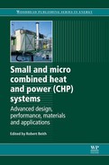
In its simplest form the Stirling engine comprises cylinder, regenerator, piston and displacer as shown in the Fig. 8.1. Fuel is burned continuously outside the engine to maintain one end of the cylinder at high temperature while the opposite end is cooled by circulating water around it. Power is derived from the pressure fluctuations acting on the working piston, as a fixed volume of working gas (sealed within the engine) is alternately heated and cooled, forcing it back and forth between the two temperature zones via the regenerator. The working gas is moved by the displacer, which is 90° in advance of the working piston. The sinusoidal waveform of the power output results in low vibration and noise levels. Thermal efficiency is enhanced by the regenerator, a heavy matrix of fine wires that acts as a repository for heat extracted from the working gas during the cooling pass to be returned on the heating pass.
One significant difference between ICE (internal combustion engines) and Stirling engines is that, in an ICE, it is possible to adjust power virtually instantaneously by controlling the fuel supply. This makes ICE ideal for automotive applications where rapid variations in power are required. However, there is a significant time delay between fuel input and power output in a Stirling engine, as there is usually a substantial amount of heat stored in the hot end, which continues to transfer energy to the working gas long after the fuel supply to the burner is cut. Although this is not a concern in stationary applications, which do not require instantaneous power variation, it is a consideration for control that there is a delay of the order of minutes between a thermostat calling for heat, the availability of heat and finally the output of power. In addition, the stored energy must be passed to the heat distribution system before the engine shuts down at the end of a heating cycle, both to avoid wasting useful thermal energy and to avoid potential damage to the engine itself.
All Stirling engines have two pistons (conceptually), one of which (known as a ‘displacer’), shuttles the working gas between the hot and cold zones whilst the other (known as the ‘working’ piston) is subject to the resulting pressure changes and does work to drive the engine. Heat is applied to the hot end of the engine by, for example, a gas burner and is removed from the cold end by means of a flow of cooling water, typically the water in a central heating system. The hot end can be as high as 800 °C and the cold end around 80 °C. The displacer shuttles the working gas between the hot end and cold end of the piston without doing any work. The resulting alternate heating and cooling of the working gas causes pressure changes which in turn exert force on the working piston which drives a generator through the crank mechanism.
8.3 Why Stirling engines are suited to micro combined heat and power (CHP)
In most texts it is stated that the key characteristics of Stirling engines which align with the requirements for micro-CHP applications are long life, long service intervals, high efficiency, low noise and vibration and low emissions. Whilst these are indeed key characteristics, the reality in execution is rather more complex.
8.3.1 Long life and extended service intervals
The requirement for long life relates to the very long operating periods required of stationary heating systems (typically around 20 000-30 000 hours for the typical 10-year life expectancy of a central heating boiler) around ten times that of a typical automotive IC engine. As far as service intervals are concerned, it is not just the cost of the service, but the frequency and intrusiveness of a service that is important; it would, for example, not be acceptable to have to undertake an oil change every 200 hours (less than a fortnight) equivalent to the 10 000 mile service intervals common to car engines.
As an external combustion engine, with a continuous combustion process there is no need for complex valving, timing gear, spark ignition and the many other service limiting components characteristic of automotive IC engines. However, the need to avoid oil migration into the upper cylinder and the consequent dry lubrication approach mean that seals and bearings are subjected to severe operating conditions. So far the WhisperGen is the only Stirling micro-CHP system to have demonstrated significant numbers of systems in the field demonstrating lifetimes in excess of 20 000 hours together with the requisite annual service intervals. It remains to be seen whether the other Stirling products approaching market which are higher efficiency and higher stressed, will achieve the same service characteristics.
8.3.2 Noise and vibration
Although the noise and vibration of Stirling engines is very much less than that of IC engines, it is extremely challenging to produce any reciprocating engine with a noise level acceptable in the occupied space of a home operating more or less continuously during the heating season. As the name suggests, the WhisperGen unit was considered relatively silent in its original application as a marine APU where the alternative would be a conventional diesel IC engine. In domestic micro-CHP applications the early WhisperGen products performed more than adequately for installation in utility rooms and garages, but were only installed in the occupied space within acoustic enclosures which performed satisfactorily when properly constructed. However, when installed in inappropriate locations or without adequate acoustic isolation, a number of users found the background noise disturbing. Unfortunately noise is a very subjective phenomenon and current guidance tends to err on the side of caution in recommending installation in utility rooms even though the sound level has been significantly reduced and is not significantly different from a conventional boiler. The wall-mounted MEC LFPSE derivatives with their characteristic 50 Hz hum are believed to suffer from noise transmission through the supporting structure and pipework with unpredictable noise breakout within the home, although customers seem to find the overall noise level generally acceptable. It can therefore be concluded that, whilst there is still some way to go in producing Stirling engines with completely unobtrusive noise levels, current products are within the boundaries of customer expectations and acceptability.
8.3.3 Low emissions
One of the primary benefits of micro-CHP is its ability to reduce overall GHG (greenhouse gas) emissions. The effective CO2 emissions associated with the production of electricity are equivalent to the lost opportunity cost of heat. In other words, electricity is produced at an effective rate of 0.22 kgCO2/kWh; this is a significant saving compared with the displaced grid electricity supply (0.568 kgCO2/kWh) with regard to GHG emissions. However, the very high temperatures in Stirling burners tend to produce higher levels of NOx than gas boilers which can operate adequately with lower flame temperatures. In the event that legislation is introduced in this area, Nox emissions could be mitigated, for example, by means of exhaust gas recirculation (EGR) without the need for catalytic converters which would be required for ICE products.
8.3.4 High efficiency
Although, as will be discussed later, electrical efficiency is not necessarily the determining factor in assessing the commercial viability of a micro-CHP product, the higher the electrical efficiency (provided it is not achieved at the expense of total efficiency) is of significant benefit as it is the value of electricity produced which justifies the investment in micro-CHP. The high efficiency theoretically achievable with Stirling engines,1 although demonstrated in laboratory prototypes, has yet to materialise in mass market products.
It appears that delivery of very high electrical efficiency imposes economic and production challenges which has meant that all domestic scale units so far at or near market have electrical efficiencies of less than 15%. However, it can be seen from the discussion below that significantly higher efficiencies are readily achievable and it is likely that Stirling engines for domestic CHP applications will continue to develop for some time, just as ICE engines have done in automotive applications.
8.4 The Stirling cycle
In a Stirling engine there is a continuous input of heat to the hot end of the cylinder, together with a continuous cooling of the cold end of the cylinder. In micro-CHP applications, the hot end is heated by a very high temperature fuel-fired burner (typically natural gas), whilst cooling is provided by the primary circuit in a conventional, hydronic (water-based) central heating system. In other words, the heat from the gas burner is transferred to the central heating flow to the radiators through the Stirling cycle in the engine, rather than directly through a conventional heat exchanger as would be found in a gas boiler.
As the Stirling engine is an external combustion engine, the gas within the pressurised cylinder is completely sealed from the atmosphere and the combustion process. It can be seen from the sectional diagram that heat can only be transferred from the burner to the working gas by conduction through the (normally finned) walls of the cylinder, one of the most challenging constraints of the Stirling engine as it is very difficult to transfer heat to the working gas or indeed to extract it given the relatively small surface areas available for heat exchange. The function of the regenerator is to optimise the efficiency of the cycle and will be described in more detail later.
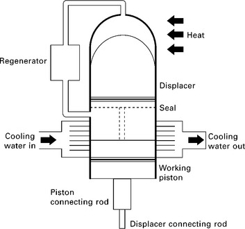
The PV (pressure/volume) diagram in Fig. 8.2 shows the theoretical thermal cycle of a Stirling engine, beginning at point 1. At this point the working gas is at its maximum volume and minimum temperature and is contained within the cold end of the cylinder. A displacer shuttles the gas into the hot end of the cylinder without doing any work and without any temperature increase. In reality, of course, work has to be done to compress the cold gas into the hot end space and inevitably the temperature does rise before reaching point 2. The practical implications of this are discussed later. At point 2, heat is added to the gas and both temperature and pressure rise towards point 3. From point 3 to point 4, the hot gas expands, exerting a force on the working piston. It is this stage that produces useful power from the engine and is known as the power stroke. At point 4 the gas is at its maximum volume and is then shuttled back to the cold end where it is cooled, ready to commence the next cycle. In theory the work done by the engine is illustrated by the shaded area between the two isotherms and vertical lines of constant volume.
8.4.1 Efficiency and other performance constraints
The diagram and cycle described above illustrate an idealised and greatly simplified process. In reality there are inevitable compromises in terms of practical design and construction. Even in this idealised diagram it can be seen that the regenerator has a certain volume which, by definition, cannot be part of the swept volume; its volume is referred to as ‘dead volume’. The WhisperGen engine, for example, is a double acting design in which each of the four cylinders is linked to its neighbour with a pipe running from the hot end of one to the cold end of the adjacent cylinder; the gas contained within these pipes also constitutes dead volume.
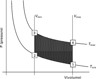
Thus, in practice, the actual thermal cycle in a typical Stirling engine is more accurately represented by the central dark elliptical shape in the middle of the graph shown in Fig. 8.3. As dead volume is reduced, the true cycle tends towards the larger (pale) ellipse which extends to the isothermal boundaries of the ideal cycle. This can be achieved for flat plate exchangers, but these tend to have very low specific power and are of little practical use for micro-CHP applications.
Also, as was mentioned earlier, the gas does not actually undergo distinct steps, but more a gradual change from one stage to another. Only in the event of discontinuous motion of the pistons can the ideal cycle be approached.2 In this case the oval is stretched as shown by the arrows; in practice, this can be imitated by complex mechanical linkages or, in the case of the linear engine, quite possibly by means of electronic actuation of the displacer at least.
The theoretical efficiency of any heat engine is limited, according to Carnot’s principle, by the relative temperatures of the hot and cold ends of the engine. To achieve maximum efficiency, it is desirable to achieve as high as possible a hot end temperature and as low as possible a cold end temperature. In practice, the maximum temperature is constrained by the availability of suitable materials to working temperatures of around 800 s°C. It should be borne in mind that the temperature of the working gas will always be lower than the material required to conduct heat to it, and that the flame temperature will be even higher than that of the conducting material. Generally high temperature alloys such as Inconel are used which are reasonably good conductors, able to withstand repeated thermal cycling and very high pressures and which can be worked albeit with some difficulty and at high cost.
The cold end temperature is constrained simply by the temperature at which the ‘waste’ heat (actually the useful heat as far as the domestic heating system is concerned) is required. Some modern heating systems have oversized radiators or use underfloor coils and operate at relatively low temperatures (30-40 °C); as with heat pumps the efficiency of micro- CHP systems is enhanced in this application. However, one of the main attractions of micro-CHP is that it can be used as a ‘drop-in’ replacement for existing homes, the majority of which (in the UK at least) are fitted with radiators designed for higher water temperatures (60-80 °C). In this case, the efficiency is marginally reduced as the ∆T is reduced from, say 760 °C (= 800-40 °C) to 720 °C (= 800-80 °C). In some instances, efficiencies quoted for Stirling engines under development in laboratory conditions are based on a cold end temperature which, although technically feasible, often using cold mains water, is of little relevance to their likely performance in the field.
The choice of working gas significantly influences efficiency; ideally the gas should have a low specific heat such that a given amount of heat input produces the maximum possible pressure increase. Both hydrogen and helium are well suited to this application although both are very ‘leaky’, i.e. difficult to contain; hydrogen actually leaks through the metal of the engine housing. For this reason the highest efficiency Stirling engines tend to use helium as a working gas, although nitrogen is an effective compromise used in the WhisperGen engine, for example.
The regenerator, generally some kind of matrix of fine wires, serves to store heat between the heating and cooling phases of the cycle; the more efficiently the regenerator can capture the heat, store it and transfer it back to the gas in each cycle, the higher, potentially, the efficiency of the engine. The Carnot efficiency limit referred to above can only be even theoretically achieved when the regenerator has an efficiency of 100%. It might therefore appear that a large, high capacity regenerator should be used in all cases to maximise efficiency. However, the volume of the regenerator comprises dead volume, and the matrix presents a parasitic pressure drop to the cycle, so there are practical compromises which need to be accepted. In some higher efficiency engines, multi-stage regenerators are used with varying matrix spacing between the hot and cold ends optimised to the flow of expanding or contracting gas.
In addition to the unavoidable compromises to the theoretically achievable efficiency of the engine design, there are further losses caused by pumping losses (in the movement of the working gas through pipes, etc.), frictional losses in the bearings and drive mechanism as well as the frictional loss in the gas seals. This latter is a key challenge to all Stirling engines, but is particularly onerous for engines using helium or other leaky gases. It is one of the reasons that Stirling engines require such high precision manufacturing tolerances to ensure that seals function effectively, but without exerting excessive frictional forces on the cylinder wall.
It can be seen from Fig. 8.2 that, where the work done in each cycle is indicated by the shaded area, then that area can be enlarged by increasing the swept volume (the difference between Vmin and Vmax), by increasing the pressure range, by increasing the temperature range (Tmax - Tmin), or any combination of these factors. Increasing the working temperature and pressure will result in a higher power density, whereas a larger volume simply represents an engine with a higher cubic capacity, just like in an IC engine. Whilst not all of these parameters explicitly increase the efficiency, in practice the frictional losses do not increase proportionally in line with power, so that a Stirling engine with a higher power density or a higher power will tend to be more efficient. As explained earlier, a high upper temperature is in any case desirable to achieve a high Carnot efficiency.
In micro-CHP applications, the final power output from the Stirling engine is required as electricity, rather than mechanical power, so that some form of generator is an essential component. These tend to be either induction generators (actually induction motors as these are mass produced and relatively inexpensive) or synchronous generators. Although the latter are more electrically efficient, they are more expensive and require power electronics to synchronise to the grid, resulting in additional losses, cost and bulk.
One drawback of induction generators is that they derive their reactive power from the network to which they are connected; whilst this simplifies synchronisation (as they automatically adjust to the frequency of the reactive power supply), it also means that the engine is tied to the grid throughout each cycle. Although the nominal rotational speed of 1500 rpm (or 3000 rpm) results in a synchronised frequency of 50 Hz, this does not necessarily mean that the power cycle of the Stirling engine delivers power evenly at a constant speed, indeed it is clear from Figs 8.2 and 8.3 that this is not the case. As a result, single cylinder Stirling engines may accelerate and decelerate to speeds alternately above and below the synchronous speed of the generator within each cycle, consequently producing in excess of their mean power at one point, whilst drawing power (motoring) at another. Not only does this impose undesirable loads on the engine and generator, it also produces wasteful heat in the generator, further reducing its efficiency.
As has been discussed earlier, in order to realise maximum efficiency it is desirable to achieve a high maximum temperature. Although Stirling engines in micro-CHP applications can derive their heat input from virtually any high temperature heat source, in practice micro-CHP products are currently focused on mass market applications, notably those with a relatively low cost (natural gas) fuel supply. Whereas in a gas boiler, the gas is simply used to heat the central heating water at around 80 °C, the Stirling engine requires combustion temperatures well in excess of 800 °C in order to transfer heat effectively to the working gas through the limited heat exchange area available. It is a fundamental law of physics that high temperature energy is more useful than low temperature; it is therefore clear that it is rather wasteful to heat up the ambient air/fuel mixture from, say 10 °C to 1000 °C entirely by burning additional fuel, when the exhaust from the engine can be well over 500 °C and is simply recovered in a low temperature heat exchanger to add additional heat to the central heating circuit at a mere 80 °C. High efficiency engines thus use a recuperator (also known as an air pre-heater) to recover heat from the high temperature exhaust gas and transfer it to the incoming combustion air supply. However, this component is often omitted due to cost, bulk or because it constrains the ability to make use of EGR.
It can thus be seen that a number of factors, practical and theoretical, constrain the efficiency which can be achieved in Stirling engines. However, even current micro-CHP products which achieve efficiencies of up to 15% show clear promise of a potential evolution as the technology matures in this application.
8.5 Types of Stirling engine
All Stirling engines fall into one of the following two basic categories:
• Kinematic Stirling engines have a crank arrangement to convert the reciprocal piston motion to a rotational output, say to drive a generator. The displacer is actuated through some form of mechanical linkage.
• Free-piston Stirling engines (FPSE) have no rotating parts. In the majority of cases, output power is taken from a linear (usually permanent magnet) alternator attached to the piston, while the displacer is actuated by the pressure variation in the space beneath the piston.
In theory the LFPSE (linear free piston Stirling engine) is much simpler as it contains fewer moving parts. In practice, the challenges of differential expansion and linear generator design have so far proved a major obstacle to commercialisation.
Stirling engines can be further characterised by the three typical configurations of the displacer and working pistons, known as alpha, beta and gamma. In the alpha type, the working gas shuttles between two pistons. One piston carries out compression in the cold space and the other, expansion in the hot space. A sub-division of the alpha type is the double-acting type, where useful work is done by symmetrical pistons. In the beta type, both compression and expansion are carried out by the working piston, the working gas being shuttled between hot and cold spaces in the same cylinder by means of a (non-working) displacer. The third version is the gamma type in which the working piston is placed in a separate cylinder.
It has been shown that the beta type is inherently more efficient than the others,3 but as will be explained later, high efficiency alone is not necessarily a desirable goal. Indeed, measures which improve efficiency may have undesirable consequences both in technical and economic terms. Clearly there is little point in achieving a high efficiency if the production costs are so high that it could never be recovered from energy savings. For example, it is possible to improve the Carnot efficiency of a Stirling engine by using discontinuous motion of the piston. Practical implementation of this feature is possible using electromagnetic actuation of the displacer, and is to some extent simulated in the conventional crank arrangement of some engines. However, fluctuations in rotation of the working piston give rise to other complications, particularly variations in electrical output and high electrical losses as well as obvious increases in noise, vibration and mechanical stress.
Thus, the quest for high efficiency has economic and performance implications which may be undesirable. Indeed, the appearance of the WhisperTech engine with an inherently low electrical efficiency, but with reliability and production cost parameters in line with market requirements, can be seen as a major landmark in the commercialisation of micro-CHP.
8.6 Development of Stirling engines for micro combined heat and power (CHP) applications
In the 1970s the quest for improved efficiency promised by Stirling technology led to attempts to develop automotive power units. However, the lack of controllability required complex gas valving arrangements with high parasitic losses, somewhat defeating the point of the exercise. Even after the abandonment of Stirling as direct drive automotive unit, problems with lubrication and working gas pressure loss remained significant obstacles. Due to the very high working gas pressures, particularly with ‘leaky’ gases such as helium (selected for their small molecular size and heat transfer efficiency), leakage to atmosphere could only be contained by high loss seals. Shaft seals were initially subject to side forces, as were the piston seals, so efforts were made to minimise lateral forces with patented mechanisms (e.g. Carlqvist), reducing wear as well as frictional losses. At the same time as gas was leaking out, lubricating oil had a tendency to migrate into the hot end of the cylinders where it carbonised on the heat exchange surface, reducing heat transfer, power and efficiency.
The solution was to incorporate the generator within the hermetic envelope of the engine so that the crankcase was at mean operating pressure. The only penetrations of the crankcase were electrical leads so that no high pressure (high friction loss) moving seals are required. This feature is now found on almost all micro-CHP Stirling engines, although the Solo engine (10 kWe) simply provides constant top-up of leaking helium by provision of a cylinder of compressed gas, replenished annually. The problem of oil contamination was resolved by use of dry seals located within the cooler area of the cylinder using Teflon type materials.
This section describes a number of leading Stirling engine technologies and their individual approaches to overcoming some of the key technical challenges.
8.6.1 WhisperGen kinematic Stirling engine
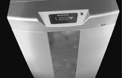
The WhisperGen micro-CHP unit is marketed in the UK by the energy company E.ON, in the Netherlands by Magic Boiler Company and in Germany by Sanevo. It is a four cylinder unit which overcomes the issues discussed earlier relating to the single cylinder asynchronous unit and leads to smooth, vibration free operation, with noise levels similar to a domestic freezer. The MkV unit, incorporating a supplementary burner, was introduced in 2005 to provide additional flexibility, making the unit suitable for larger homes. This variant also incorporated an integral acoustic enclosure which made kitchen installation possible. In January 2008, WhisperGen announced the establishment of a joint venture (EHE) with Spanish white goods manufacturer Mondragon CC to mass produce units for the European market; in late 2009, the first units (designated EU1) were dispatched from their production facility at Tolosa in Northern Spain.
The WhisperGen micro-CHP unit, from its earliest example as a diesel- fired DC battery charger for marine applications, arguably represents the first modern commercially available Stirling engine and is certainly the first viable micro-CHP product. Its success lies less in any claimed efficiency, more in its construction using conventional materials and production techniques which allow realistic manufacturing costs to be achieved. The engine uses relatively low pressure nitrogen, low head temperature and a low efficiency regenerator, all of which result in an electrical efficiency of no more than 11%. However, the relatively low investment cost is readily recovered with these performance parameters and the key benefit of reliability and extended service intervals leads to a viable product.
It is essentially a four-cylinder double-acting, alpha-type engine, similar to the configuration of the larger (10 kWe) Solo engine. However, its novelty lies in the mechanism for translating the reciprocating motion of the pistons into rotation suitable for connection to a conventional generator. Whereas the Solo engine uses conventional cross heads with oil lubrication, the WhisperTech unit uses an ingenious ‘wobble-yoke’ mechanism, the centre of which is linked through a nutating bearing to the generator rotor.
In 1999, following extensive economic and market studies,4 the UK consultancy EA Technology demonstrated the commercial viability of the unit. Laboratory tests validated the key performance parameters and demonstrated the endurance through accelerated life testing.5 It was decided to continue the commercialisation of the unit and limited field trials in the heating season of 2000-2001 further validated the anticipated performance.6 However, a number of recommendations from the trials were implemented in a modified product which was installed in 20 homes in the north west of England and ran through the 2001-2002 heating season, with a further trial of 30 homes in the north west and eastern England. These trials effectively demonstrated the performance of the WhisperGen unit in a range of typical UK homes, and helped to confirm the identified target markets.7
However, in 2006, E.ON took the decision to postpone their previously announced mass market launch pending the availability of mass manufactured products from the factory in Europe. It is expected that, following proving trials during the 2009-2010 heating season, products may again become available in late 2010.
The EU1 will have an electrical output of 1 kWe, together with a thermal output of 7 kWt from the engine, plus a further 7 kWt from the supplementary burner. An outside temperature controller is used to ensure the majority of heat is delivered by the engine, thus maximising run hours, unless the ambient temperature is extremely low, in which case the supplementary burner is brought into operation. It is recommended for homes with a design heat loss between 5 and 12 kWt; the additional 2 kWt capacity is intended to allow for simultaneous provision of space and domestic hot water. To avoid excessive cycling, homes with a design heat loss of less than 7 kWt should be provided with a primary thermal store. The engine no longer includes an air pre-heater in order to reduce cost and size of the production units; the consequent loss of efficiency has been compensated for by a number of minor modifications including an increase in working pressure and a higher efficiency regenerator.
The unit (Fig. 8.4) is floor-mounted, about the size of a dishwasher and weighs around 140 kg, making it suitable only for installation at ground level on a solid floor.
8.6.2 MEC (Microgen) linear free piston Stirling engine
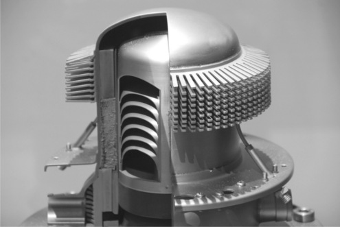
The Microgen unit, developed by BG Group from a US (Sunpower) design, is a LFPSE which is intended for wall-mounting; it contains a supplementary burner which enables it to meet the full heating requirements for even larger homes. Following disposal by BG Group in 2007, development of the Microgen unit was taken over by MEC, a consortium of gas boiler companies (Viessmann, Baxi, Vaillant, Remeha) and Sunpower. Each of the boiler companies is expected to market their own variant of the micro- CHP unit incorporating the MEC engine. Trial versions of the unit being demonstrated in the field make use of engines produced in Japan, although mass manufacture of engines has recently been transferred to China. Earlier versions produced 1 kWe from the linear generator, together with 3 kWt heat output, implying an efficiency of around 20%. However, current models have the same electrical output, but with a higher thermal output (6 kWe), implying an electrical efficiency of around 13%.
Figure 8.5 shows a cross section through the upper cylinder, with the characteristic Inconel fins designed to conduct heat effectively through the relatively small surface area of the hot end of the cylinder. The lower heat exchanger transfers heat to the cooling circuit. The multiple diaphragms are designed to strengthen the working piston which is subjected to significant pressure fluctuations.
The unit is equipped with a very large supplementary burner of around 18 kWt depending on the manufacturer. In the case of the Remeha unit, the supplementary burner is used to provide all the domestic hot water as in a combination boiler. Although this overcomes some of the inefficiencies of hot water production in summer common to all boilers and particularly poor for high thermal inertia Stirling engines, it also means that the total annual run hours will be significantly reduced, limiting the economic value of the electricity generated as a by-product of heat production.
The sunpower engine on which it is based is a beta-type, linear free piston Stirling engine (LFPSE) with an integral linear alternator. The free-piston arrangement eliminates the need for a crank mechanism, and avoids a potential source of failure. LFPSE units are thus fundamentally elegant in engineering terms, but in reality a number of technical challenges remain, which detract somewhat from their simplicity. Firstly, linear alternators are not commonly available, and developers are thus faced with the prospect of parallel development of engine and generator. The gas bearings, which avoided another potential point of failure, have, for practical reasons, been dropped in favour of diaphragm springs as used on the Infinia engine. There are also fundamental challenges as the displacer is operated by resonance and is thus tuned to the operating frequency of the engine. This can cause difficulties during start-up and stopping and several LFPSE engines are known to suffer from the piston ‘slamming’ against the cylinder ends during these periods. Similar problems may arise where grid frequency is subject to significant fluctuations. In addition, the need for very small clearances between the components of the alternator (to minimise losses) causes problems due to differential expansion as the engine heats up.
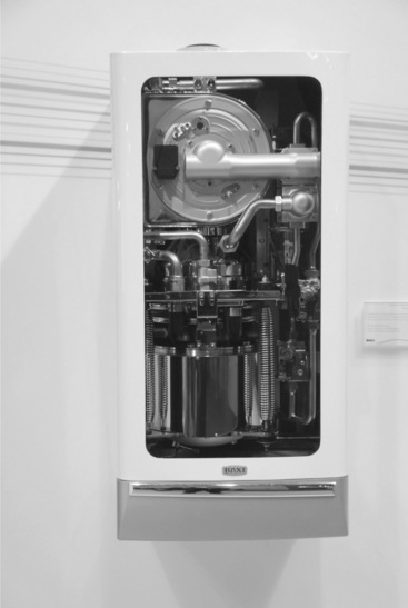
The two boiler manufacturers planning to launch the product in 2010, Baxi in the UK and Remeha in the Netherlands are both producing what is claimed to be a wall-mounted boiler replacement as this represents the largest market share in both countries. However, both units are very much larger than wall-mounted boilers and require special lifting gear to manoeuvre the unit into place and support it during fixing.
Figure 8.6 shows the Baxi unit complete with the industry standard Gianoni stainless steel heat exchanger (and supplementary burner) located above the primary (engine) burner. The engine assembly is suspended from the central plate by an arrangement of springs and a 9 kg counterweight assembly is similarly suspended to counteract the resonant vibration which is inherent in any LFPSE engine design.
8.6.3 Infinia (STC) linear free piston Stirling engine
The Infinia (formerly known as STC) LFPSE is now being used in a collaboration between Ariston (formerly MTS), Bosch and Enatec in Europe as well as Rinnai in Japan. Rinnai will produce the LFPSE module for integration into micro-CHP packages by the other partners for the European market, with a trial of 1000 units planned for 2008-2010. Rinnai will also produce a packaged unit for the Japanese market.
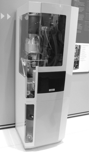
Bosch initially produced a wall-mounted version similar to the MEC configuration, but has subsequently adopted a common design approach with Ariston in producing an integrated LFPSE, supplementary burner and hot water storage cylinder in a floor-mounted package the size of a fridge-freezer (Fig. 8.7). The current Bosch product is being trialled in the UK in a project managed by Worcester Bosch. No firm dates have been announced for commercial launch so far.
The LFPSE component is rather similar to that of the MEC variants, with similar electrical output, although a somewhat lower claimed electrical efficiency, estimated to lie between that of the WhisperGen and MEC units.
8.6.4 Disenco kinematic Stirling engine
The Disenco unit is a kinematic design with an electrical output of around 3 kWe, significantly higher than other domestic products. The high electrical output enhances payback of the unit (which is anticipated to be significantly higher than the other 1 kWe products), although this makes the unit susceptible to the recoverable value of exported power from the unit unless it can achieve high utilisation such as in a small hotel*. In January 2008, Disenco announced a manufacturing partnership with Autocraft to produce the core engine, with packaging into a micro-CHP product by Malvern boilers and recently announced marketing deals with Endesa and Centrica.
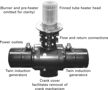
The design concept originated in the Swedish TEM design and subsequent Sigma Elektroteknisk developments in Norway, based on the ingenious Carlqvist crank mechanism. This mechanism, in conjunction with two balancing generators, converted reciprocating action into rotary motion with negligible lateral forces on the piston seals. The beta-type TEM 1-75 incorporated finned tube heater head and air pre-heater, both components contributing to the high mechanical (and consequently electrical) efficiency.
This engine drove two permanent magnet generators to produce a total of 1 kWe DC power. In 1994, it was decided to develop a unit with higher electrical output, partly funded by the EU THERMIE programme. The PCP1-130 was a considerably larger machine and the DC generators were replaced by two 3-phase 400 volt induction units, delivering a total of 3 kWe (Fig. 8.8). This design retained high pressure helium as a working gas, two-stage regenerators, the very expensive finned tube heater head and an Inconel air pre-heater. It was able to demonstrate electrical efficiencies in excess of 20%, even with grid-tied induction generators which were subsequently found to inhibit performance due to the fluctuating power output of the single cylinder design. A number of approaches were proposed which could easily have raised the electrical efficiency into the upper twenties, but Sigma were unable to continue development due to the collapse of their main shareholder, Ocean Power in the USA.
However, since the project was taken over by Disenco in the UK, the performance of the original design has been severely compromised, not least by the abandonment of the Carlqvist mechanism; Disenco have opted instead for a more conventional rhombic drive crank mechanism. It is unclear whether this is an oil-lubricated crank or whether it uses sealed roller bearings, but if the former it would be quite an achievement to have overcome the problems associated with this approach, namely oil migration into the upper cylinder and carbon deposition on the cylinder walls leading to breakdown of the heat transfer process. They have yet to demonstrate significant run hours in the laboratory or field although one unit is claimed to have operated for an undisclosed period in a single installation in the UK.
The unit is able to modulate output from 0.5-3 kWe electrical and 1217.4 kWt, with an implied electrical efficiency of little more than 15%, again illustrating how electrical efficiency tends to be compromised as products approach commercial launch. Field trials had been announced for late 2009, but following prolonged financial difficulties, in March 2010 Disenco was placed into administration.
8.6.5 Sunmachine
One of the key characteristics of Stirling engines is their ability to make use of virtually any heat source, although the majority of Stirling engine developers have understandably focused their activities on capturing the substantial gas boiler replacement market. The Sunmachine, however, is an exception, being intended as a micro-CHP system capable of burning biomass as a fuel. It is a 3 kWe product with a claimed electrical efficiency of 20% and thermal efficiency of 70%, manufactured in Germany. Wood pellets are burned directly above the finned tube heater head, similar to the TEM design. However, previous attempts at this configuration have not been successful due to problems with sooting of the heat exchanger which quickly becomes ineffective. It is unclear if or how Sunmachine have actually overcome this issue as little public information is available. Sunmachine plan to launch a biogas version of their product in 2010, although this is a far less technically challenging technology, differing little from natural gas variants; the biggest challenge is finding a supplier of biogas!
The biomass product has been repeatedly announced at a market price of around €23,000 in 2005, but which had risen to €35,000 by 20088.
8.6.6 Cleanergy AB (formerly Solo)
Although within the definition of micro-CHP, the Solo micro-CHP unit with an electrical output of 9 kWe and a thermal output of 26 kWt, is clearly targeted at commercial rather than residential installations. The Solo V160 engine is a 2-cylinder alpha-type Stirling engine designed to run on biogas and can modulate electrical power between 2 and 9 kWe with corresponding thermal output between 8 and 26 kWt. The working gas is helium and the engine achieves an electrical efficiency of over 22% (LCV). Naturally it is a substantial piece of kit (1280 × 700 × 980) weighing 460 kg.
In the V160, air is pre-heated and mixed with gas to improve efficiency; EGR is used to reduce emissions by recirculating a proportion of the exhaust gases into the combustion process which slows down and spreads the reaction in a process known as flameless oxidation (FLOX™). Although oil changes are claimed to be limited to 40 000 hours, the piston rings need replacement every 4000-6000 hours. It is also believed that the helium charge needs replenishment on a regular basis with a consumable cylinder being provided with every unit.
8.7 Micro combined heat and power (CHP) design and system integration
In order to extract the maximum value of micro-CHP it is necessary to optimise the overall performance of the micro-CHP package within the energy system of the application. This means that not only must the performance of the Stirling engine be optimised in its own right, but that the ancillary components in the micro-CHP package as well as its interaction with the domestic energy system be carefully considered. It is, in many cases, necessary to accept compromises in efficiency in order to achieve a robust and practical micro-CHP system. This point has been discussed previously in the context of achieving high electrical efficiency of Stirling engines by operating at high temperature and pressures, but it is equally relevant at the system level, where the micro-CHP interfaces with what is in most cases a sub-optimal heat distribution system.
8.7.1 Design for thermal efficiency
Although the key value of micro-CHP is determined by its ability to generate high value electricity instead of less valuable heat, it is also necessary to ensure that the total efficiency, that is electrical and thermal efficiency combined, is not unnecessarily compromised. As discussed earlier, the specific carbon dioxide emission of micro-CHP generation is adversely impacted if electricity is generated at the expense of a high thermal loss. So considerations of micro-CHP economics and environmental benefits require careful consideration of the balance of heat and electricity outputs.
In the earlier discussion of Stirling engine efficiency, it was explained that the efficiency of the Stirling engine is fundamentally determined by the difference in temperature between the hot and cold ends of the working cylinder; the Carnot efficiency is constrained by this temperature difference. The efficiency of the engine in turn determines the electrical efficiency of the micro-CHP package. However, for optimum overall efficiency, the thermal efficiency must not be neglected.
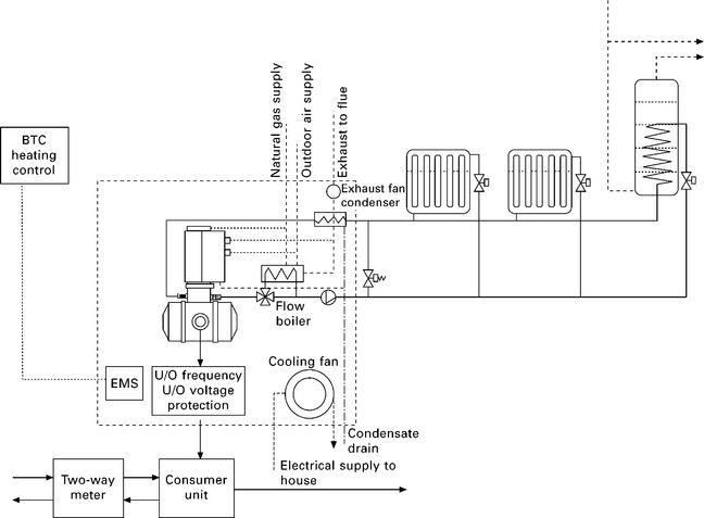
Based on the high efficiency Sigma Stirling engine which includes an air pre-heater, it can be seen in Fig. 8.9 that the residual heat in the flue gases is passed to a heat exchanger in the return water from the primary heating circuit as it is at too low a temperature to add significantly to the temperature of the flow from the engine. In early versions of the WhisperGen engine, flue gases passed first through a relatively low capacity air pre-heater and then to the heat exchanger in the primary circuit. In the first case it is apparent that the return water temperature is increased by this process, adding to the thermal energy recovery, but resulting in a smaller temperature difference in the engine. However, in both cases it was concluded that the small loss in electrical efficiency was more than compensated for by the significant increase in thermal efficiency due to the potential for condensation of the flue gas in the low temperature return heat exchanger. Indeed, the potential efficiency increase between non-condensing and condensing operation undergoes a step change of up to 10%, just as with gas boilers. However, it is essential to closely control the amount of heat input to the heat exchanger from the supplementary burner which, in the WhisperGen unit, utilises this ‘ secondary’ heat exchanger as its only means of delivering heat to the primary central heating flow; it is otherwise quite possible that the rise in temperature in the primary flow can result in raising the temperature of the cold end rather than lowering it, causing inefficiency and potentially damage to the engine.
The precise balance of energy recovery is rather complex, depending on the temperatures at the various stages of the Stirling process and can vary greatly depending on the operating temperature, degree of air pre-heat and capacity of the flue gas heat exchanger.
Again, as with gas boilers, there is some concern that thermal efficiencies achieved under idealised test conditions are not replicated in the field. Condensing boilers which can readily achieve efficiencies in excess of 90% in the laboratory do not benefit from low return temperatures (the prerequisite for condensing, high efficiency operation) under full load conditions except with well-designed radiators or during the initial warm-up period at the start of each programmed heating cycle. For this reason, in some instances an additional heat exchanger is located after the flue gas heat exchanger as a secondary air pre-heater. This has the effect of virtually guaranteeing condensing operation as the incoming air will, almost inevitably, be below 20 °C whenever space heating is required, providing a cold enough heat exchanger surface to ensure condensation occurs.
8.7.2 System design
Although the micro-CHP unit is essentially a replacement for a gas boiler, it has peculiar characteristics which mean that it cannot be treated in exactly the same way either from a design, installation or operational point of view. It may be a ‘drop-in’ replacement as regards the home, but the designer, the installer and the householder need to understand a number of key issues if the system is to perform at its best and to avoid disappointment for the user. One of the key requirements of a micro-CHP system as discussed earlier is to maximise the number of run hours each year in order to generate as much valuable electricity as possible. Not only does this imply a more accurately designed system, it also means that the householder may need to become accustomed to a somewhat different control approach.
For example, optimum start controls which are designed to achieve comfort conditions regardless of outdoor air temperature, are regarded with some suspicion by householders who cannot understand why the heating system comes on at different times every day (as a function of outdoor air temperature) even though they have set what they believe to be a start time for the central heating. In other words they fail to distinguish between setting the programmer to turn on the heating system at, say, 07:00 and setting the programmer to make sure the house is at the desired temperature by 07:00. in the optimised start programmer the control algorithm calculates the required start time based on the thermal inertia of the building, the necessary temperature lift (i.e. difference between current and desired temperature) and the heat loss deduced from the outdoor air temperature.
Of course, it is perfectly possible to design a micro-CHP system to perform in largely the same way as a gas boiler; the majority of micro- CHP packages now incorporate some form of supplementary burner with a significantly higher thermal output than the prime mover, so it is quite simple to use this capacity to achieve the rapid heat up which householders are accustomed to. However, this results in sub-optimal operation in which the potential value of electricity generation is squandered simply to avoid control complexities or to avoid the need to accommodate a HWC in the system.
In the case of the Remeha product, domestic hot water is provided entirely by the supplementary burner, replicating the performance of a combi-boiler, but typically losing the opportunity to generate 1000 kWh of electricity annually, worth around £100.
The WhisperGen unit, although configured as an integrated system boiler linked to a conventional hot water cylinder, offers users the facility to control the supplementary burner (which is triggered by the rate of increase in flow temperature, a proxy for the ability of the system to meet the instantaneous thermal demand) by means of a timed delay. The longer the delay, the less heat is provided by the supplementary burner and the more is provided by the engine, resulting in longer run hours and enhanced electricity production. However, this enhanced electricity production is achieved at the expense of longer recovery times of the hot water in the HWC for example; this can be effectively overcome by incorporating a larger capacity HWC, but this has implications for cost, space and standing losses. As always, it is a matter of compromise between theoretical efficiency and pragmatism.
As with condensing boilers, the thermal efficiency of Stirling engine micro-CHP is constrained by the return temperature which should ideally be kept at a temperature low enough to induce condensation and thus recover latent heat from the condensate in the flue gases. However, unlike heat pumps the performance of these units is not significantly compromised by the need to deliver DHW at a relatively high temperature as they are easily capable of delivering hot water at similar temperatures to a gas boiler.*
8.7.3 Interface design
Very often, existing central heating systems with radiators, particularly open-vented systems, contain substantial amounts of sediment and other undesirable contaminants in the primary heating circuit. Although this impacts on the performance of conventional boiler heating systems with a reduction in heat transfer capability and increased pump power, the problem is more acute for micro-CHP systems. Stirling engine heat exchangers are particularly susceptible to the accumulation of contaminants in their ‘ cooling circuit’ (the primary heating circuit as far as the house is concerned) as they need to transfer substantial amounts of heat through a relatively small area (at the cold end of the piston) and consequently tend to have very fine heat exchanger elements which are relatively prone to clogging.
8.8 Applications and future trends
Stirling engines have historically been identified as the leading micro-CHP technology for individual homes, a role for which they are showing ever increasing promise. However, given the increasing availability of low cost, reliable and efficient ICE-based products suitable for small commercial applications, it is difficult to see how the larger output Stirling products, such as the Solo unit, can continue to compete. After all, the very characteristics which make Stirling engines attractive to householders are of less relevance to those installations where a plant room is available and service can be carried out on a normal commercial basis.
Chapter 13 describes the potential for the various micro-CHP technologies in more detail, but as a rule, the key characteristics of Stirling micro-CHP including their relatively high heat-to-power ratio, make them eminently suitable for the majority of the existing UK housing stock with average annual thermal demands of around 18,000 kWh and where thermal and electrical demands are in similar proportions to the outputs of the Stirling technology, namely around 6:1.
Stirling engine micro-CHP is a particularly effective solution to the provision of low carbon heat and power in those homes for which it is difficult to identify alternative energy efficiency solutions, for example, homes which have solid walls and are thus difficult to insulate further, or larger homes which have already had all cost-effective measures applied, but which still have significant thermal needs. These latter also tend to have adequate space to accommodate what are today, relatively bulky floor-mounted Stirling-based micro-CHP products, often with separate utility rooms.
However, there is a practical need for different configurations to meet demands of different types of homes. An increasing proportion of gas boilers installed in the UK are wall-mounted and combi-boilers are becoming increasingly popular; although the MEC-based products claim to be wall-mounted, their weight in excess of 100 kg makes them very difficult to handle and install. It remains to be seen whether lighter units will be developed or whether Stirling engines will be limited to those applications where either a floor-mounted unit is acceptable or a substantial structural wall is available. And, whilst the Remeha unit already addresses the challenge of a combi configuration, the reduced potential for electrical generation may limit the economic viability to properties with larger thermal demands than the average UK home.
It is quite possible that the different drivers in other markets may result in the development of products with characteristics readily transferable to those of the UK. So, whilst German homes often incorporate spacious basement areas which can readily accommodate existing Stirling products along with the performance enhancing thermal storage vessel without difficulty, Dutch homes often include the boiler within the roof space due both to space constraints and to facilitate flueing; they may not incorporate any thermal storage at all. It is no surprise therefore that the Remeha product is configured as a wall-mounted, combi package.
Along with these ongoing developments to match the demands of different configurations, there is likely to be significant development in the performance of Stirling engine technology; there is certainly substantial theoretical room for increased electrical efficiency as has been demonstrated by numerous laboratory prototypes.
We should also expect to see the production cost fall in response both to increased volumes and to compete with alternative products such as high performance fuel cells as they reach the market. If Stirling engines are to remain competitive they must do so on the basis of low initial cost; they are incapable of achieving the electrical efficiencies of SOFC technologies.
In the longer term, beyond say 2030, there is some concern regarding the availability of natural gas or other fossil fuels for Stirling engines. Against this, external combustion engines generally are able to make use of a wide range of fuels, at least in theory; already a limited number of biomass products are emerging and it is relatively simple to convert burners from natural gas to biogas (simple combustion is less of a challenge than combustion in an ICE). However, it should not be assumed that the rather limited biofuel resources likely to become available on a global scale will necessarily be supplied for combustion in the domestic heating sector. It may be, however, that limited quantities of natural or biogas will be used in hybrid domestic systems, perhaps incorporating heat pumps making use of intermittent renewable electricity, backed up by gas-fired micro-CHP during periods of peak demand or capacity shortfall.
8.9 Sources of further information and advice
• Information on Stirling engine micro-CHP including links to manufacturers’ websites: http://www.microchap.info/stirling_engine.htm
• General information on micro-CHP and related technologies with links to additional resources: http://www.microchap.info
• General information on microgeneration technologies with links to manufacturers and additional resources: http://www.microgeneration-oracle.com/index.htm
• Links page to government and institutional websites providing information on energy issues as well as organisations active in the field of distributed energy in general and CHP in particular: http://www.microchap.info/LINKS.HTM
8.10 References
1. Egnell, R., Gabrielsson, R. Alternativa motorer. Stockholm: NUTEK; 1991.
2. Kolin, I. Stirling motor. Zagreb University; 1991.
3. Finkelstein, T. Stirling Conference. Osnabruck; 1998.
4. Winstanley, R., et al. WhisperTech WG800 Stirling engine micro CHP economic viability report. EA Technology client confidential report; 1999.
5. Winstanley, R. WhisperTech WG800 laboratory tests. EA Technology client confidential report; 1999.
6. Winstanley, R. Micro CHP sheltered field trial report. EA Technology client confidential report; 2001.
7. Green, R. WhisperTech alpha trials report. EA Technology client confidential report; 2002.
*The new FiT (Feed in Tariff) introduced in April 2010 in the UK would make a very significant beneficial impact on the economic viability of this product and others with similarly high electrical power outputs; it allows for a subsidy of 10p/kWh of all power generated regardless of whether it is consumed on site or exported in addition to an export payment of 3p/kWh.
*Early Stirling engine-based micro-CHP products tended to limit the flow temperature to around 70 °C in order to maintain a cold end temperature that would avoid any possible damage to the piston seals which were considered a vulnerable component. The availability of improved materials and better temperature control have largely overcome this issue and current units operate at similar temperatures to gas boilers, although performance is enhanced by maintaining the highest possible temperature difference between hot and cold end.