
Thermal-engine-based small and micro combined heat and power (CHP) systems for domestic applications: modelling micro-CHP deployment
Abstract:
In order to reduce demands on central energy supplies and to reduce carbon emissions, a number of technologies are being developed for application in domestic and commercial buildings. Micro (or domestic) and small CHP is one of such technologies. First, Section 18.2 describes types of thermal engines used as prime movers in CHP systems. Section 18.3 briefly reviews recent CHP appliance developments with thermal engines. Section 18.4 gives an overview of general principles used in modelling MCHP deployment in a household and estimation of benefits. Sections 18.5 and 18.6 demonstrate principles of obtaining typical heat and power demand profiles in an average household. Section 18.7 presents information on experimental performance mapping of a MCHP system on the test rig simulating a hydronic heating system in a semi-detached house. Finally, Section 18.8 provides an example of how the operation of an MCHP was simulated within a household, taking into account information generated on heat and electricity demands and data on the experimental performance of the MCHP system. Additionally, a summary of estimation of economical and environmental benefits from deployment of a MCHP system is presented in this section.
18.1 Introduction
There is a need nationally to use less energy and in the short term, energy efficiency across all sectors will be one of the most effective tools against the predicted environmental effects. Depending on the area, improved efficiency can come from behavioural changes (e.g. minimising energy waste) and implementing novel and advanced technology. The latter include more efficient and ‘cleaner’ industrial process equipment, transport with lower emissions/mile, buildings with improved passive thermal properties, improvement in the efficiency of electrical appliances, reduction of standby power in electronic devices, distributed generation, etc.
One of the key targets for increased efficiency for many years has been buildings. Vast quantities of energy are used for controlling the climate within both residential homes and commercial properties. Over 50% of greenhouse gas emissions in the UK come directly or indirectly from buildings.
A number of technologies were earmarked for promotion within this sector and these included conventional products such as condensing boilers, energy saving lights and cavity wall insulation, but also micro-generation technology such as photovoltaics and, the subject of this paper, micro- and small-CHP (combined heat and power) units.
Small gas and vapour/steam turbines, internal combustion engines and Stirling engines with power up to 50 kW and different types of fuel cells are all considered as contenders for application as heat-to-electricity converters in small- and micro-CHP units. Each of the above energy converters has advantages and limitations of design and operational features. There is a continuous ongoing debate between specialists as to which technology is most suitable and statements are made suggesting that there might be a niche market for each, or most of, these technologies.
It is not a goal in this chapter to compare technical and economical performance of the various above converters, but to concentrate on providing a deeper insight into micro- and small-CHP technology, based on thermal engines. The experience accumulated and the technology evolved make it possible to make significant and rapid progress in the development of commercial and domestic CHP systems. A number of industrial companies across the world have announced readiness for commercial production of their micro- and small-CHP systems with the power ranging from 0.5 to 50 kWel.
18.2 Prime movers deployed in micro and small combined heat and power (CHP) systems
18.2.1 Rankine and organic Rankine cycle machines
In the Rankine cycle, water is converted into the relatively high pressure and temperature water vapour (steam) in a special high temperature heat exchanger (boiler/steam generator). This vapour is then used to expand and drive a prime mover. After the expansion process, vapour may be partially converted into the liquid and at the end of expansion this relatively low pressure and temperature liquid-vapour mixture is circulated through a low temperature heat exchanger (condenser) in which all vapour is converted into the liquid state due to the cooling process. This liquid then is returned to the boiler/steam generator using a small feed pump. In organic Rankine cycles (ORC) special organic fluids with lower boiling temperatures are used instead of water. The thermo-physical properties of such fluids allow a greater power output to be achieved for the same identical dimensions of the prime mover and of heat exchangers and the working fluid mass flow.
Prime movers are usually reciprocating piston (Rankine cycle), scroll or screw (organic Rankine cycle) mechanism machines. Figure 18.1 shows schematic of a double-acting piston arrangement in which steam or vapour is supplied in turn into cylinders on the left and right. When steam is directed into the left cylinder, this coincides with a discharge of vapour from the right cylinder. The pressure of steam drives pistons which are connected to a linear rotor of a linear alternator, used to convert kinetic energy of linear piston motions into electricity.
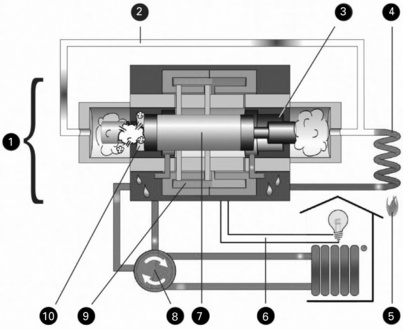
18.1 A schematic of the steam/vapour engine with reciprocating pistons and a linear alternator 1 - the linear converter; 2 - the high pressure steam pipe; 3 - the right cylinder; 4 - the steam generating heat exchanger; 5 - the burner; 6 - connection to grid/load; 7 - the reciprocating core of the linear generator; 8 - valve; 9 - stator of the linear generator; 10 - the left cylinder. (the schematic is courtesy of OTAG [1]).
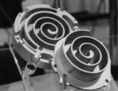
A scroll engine employs two identical involute spiral shape scrolls which are mated together inside the casing forming concentric spiral shapes (see (Fig. 18.2). During expansion, vapour formed in heat exchangers enters a casing through the inlet port in the centre of the casing and expands in crescent-shaped gas pockets forcing the orbiting scroll to orbit around the fixed scroll in the casing. The orbiting scroll is connected to the rotating shaft with a rotor of an alternator. During a single orbit, expansion of vapour takes place simultaneously in several gas pockets formed by two scrolls, providing smooth, continuous operation of the engine. After expansion the fluid/vapour mixture leaves the casing through the exhaust port.
The rotary screw engine layout is illustrated in Fig. 18.3. The engine consists of two intermeshing screws or rotors (also called male and female rotors, respectively) which trap gas between the rotors and the compressor case. Both rotors are encased in a housing provided with gas inlet and outlet ports. High pressure vapour enters the casing and expands forcing two meshed rotors into rotational motion. The male rotor is connected to a rotor of an alternator.
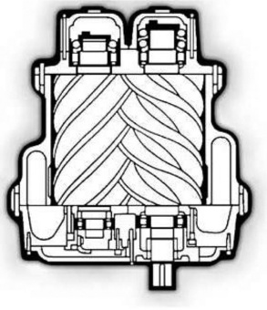
In both cases, engine lubricant is mixed with vapour and also used for cooling and sealing purposes.
18.2.2 Internal combustion engines
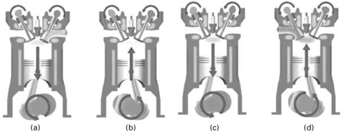
Internal combustion engines have been in commercial production since the second half of the nineteenth century and presently this is a mature and very well-established technology. The engines used for CHP are usually four-stroke machines with one or several cylinders depending on the power output required. The fuel is natural gas from mains, biofuels, biogas (formed in bio-digestion) or syngas (produced as a result of biomass gasification). In these engines a combustion chamber in each cylinder is formed by the top of the piston, the head of the cylinder with built-in inlet and exhaust valves, and a cylinder liner (see Fig. 18.4). In micro-CHP systems natural gas is usually used as fuel and engines deployed are a single cylinder spark ignition engine. The spark plug is also built in the head of the cylinder. In order to avoid overheating of components during the engine’s operation, there are water jackets in the cylinder and in its head. Engines used for CHP have, as a rule, a conventional crank-shaft drive mechanism, placed in the crank-case below the cylinder/s. In such a mechanism the piston is connected to the shaft using a rod and the reciprocating motion of the piston is converted into rotational motion of the shaft. Natural gas and air are mixed in the inlet manifold before entering the cylinder. The cycle starts when the piston is in its top position in the cylinder and can be split into four stages: induction stroke-air-gas in (see Fig. 18.4(a)); compression stroke – all valves are closed (see Fig. 18.4(b)); combustion and expansion stroke (see Fig. 18.4(c)); exhaust stroke-combustion products are forced out of the cylinder (see Fig. 18.4(d)).
18.2.3 Stirling engines
The Stirling engine is the common name for an external combustion heat engine which works on a closed regenerative cycle. Various design configurations have been developed for a wide range of applications which include solar dish/engine installations, biomass systems, air independent submarine propulsion systems, on-board power systems for deep-space missions, etc. This sub-section is focused only on Stirling engines developed for small- and micro-CHP purposes.
The operational principle of this engine remains the same as for any heat engine: the useful power output work generated during expansion of the working fluid should be greater than the work used to compress the working fluid during the working cycle. The major feature of the Stirling engine is that the working fluid is sealed inside the engine’s volume and heat is transferred to and from the working fluid and from and to the internal gas circuit, respectively, through specially designed heat exchangers, namely a heater and a cooler, which are parts of the engine’s design and maintained at constant high and low temperatures, respectively.
Figure 18.5 presents an example of a design arrangement of a Stirling engine. In this arrangement the engine has two variable working spaces, namely expansion and compression spaces, located in separate cylinders, namely ‘hot’ and ‘cold’ cylinders with their own pistons. These working spaces are connected to each other via channels of three special heat exchangers integrated into the design of the engine, namely the heater, the regenerator and the cooler. The walls of the ‘hot’ cylinder and the heater are kept at elevated temperature, using some heat source (combustion of fuels, nuclear heat, concentrated solar radiation, etc.). Similarly, the walls of the ‘cold’ cylinder and the cooler are kept at a lower temperature (e.g., using a cooling water jacket). The movements of the pistons are synchronised and arranged in such a way that the ‘hot’ piston leads by approximately 90-120 degrees of the crank-shaft angle. Such motions of the pistons result in the gas being located mainly in the ‘hot’ cylinder during the expansion stroke (heat is introduced into the cycle) and in the ‘cold’ cylinder during the compression stroke (heat is rejected from the cycle).
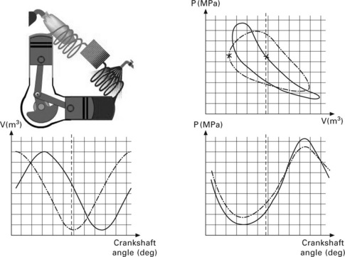
18.5 An example of a Stirling engine design arrangement and of a variation of the gas pressures and volumes in the 'hot' and 'cold' cylinders of the engine and pressure-volume diagrams.
Heat exchangers for the introduction of heat (a heater) and its rejection (a cooler) should have a surface-to-volume ratio as large as possible. The regenerator, which is placed between the heater and the cooler, represents a porous medium enclosed in the metallic casing. This porous medium is made from a material with a high heat capacity and should ideally have an infinite radial and zero axial conductivities. It acts as a heat sponge: heat is transferred to the material of the regenerator and stored when the working fluid flows from the ‘hot’ to ‘cold’ zone. The stored heat then is returned to the working fluid when it flows in the opposite direction. Thermo-insulation is usually used to separate the porous medium from the walls of its casing in order to reduce heat losses.
The volumes of heat exchangers and of pipe joints are so-called ‘dead’ volumes since these decrease the compression ratio, which is the ratio of maximum and minimum volumes of the engine. In order to obtain high power output and efficiency, it is necessary to keep the compression ratio of the engine as high as possible. In Stirling engines the typical value of the compression ratio is about 2.
Figure 18.5 also shows examples of the variation of the volumes in the ‘hot’ and ‘cold’ cylinders, the gas pressure of such engines and their pressure-volume diagrams over a single cycle. The difference in areas of the pressure-volume diagrams for the ‘hot’ and ‘cold’ cylinders represents work produced in the cycle (the indicated cyclic work). The product of the indicated cyclic work and the number of cycles completed per second is called the indicated power of the machine.
The thermodynamic efficiency of the ideal Stirling cycle with an ideal regenerator is equal to the efficiency of the Carnot cycle. In practice, the effective efficiency of existing Stirling engines is somewhat close to, or even less than, that of spark ignition engines, although there is great potential for improvement.
Stirling engines can use any source of heat: fossil fuels (liquid, gaseous, coal), radioisotopes, burning of metals and renewable energy (hydrogen; biomass fuels in solid or gaseous state from wood, straw, etc., sewage; landfill gases; direct or accumulated solar radiation heat). When using fossil fuels, a continuous combustion process takes place in the burners and using different techniques it is possible to achieve a very low level of pollutants in flue gases. There is no explosive combustion of fuel in the cylinders and burning occurs at relatively low pressures. Furthermore, as there is no valve-train mechanism, the noise in an operating Stirling engine is significantly lower in comparison with internal combustion engines. When necessary, special drive mechanisms can be used to provide an almost ideal dynamical balancing of the engine, which virtually eliminates vibrations during its operation. The variation of the engine’s torque is significantly smoother than that in internal combustion engines.
The fraction of the heat rejected from the cycle into the cooling system of the engine is approximately double that in internal combustion engines. This heat then can be used for CHP purposes. Gases with a high heat capacity and low viscosity, such as hydrogen and helium, are used in machines with a high performance. The pressure inside the engine may be up to 220 bar or greater, hence special attention should be paid to the sealing to prevent the leakage of these gases. To restrict costs, engines may be designed to run using air, nitrogen and other easily available gases. However, this results in an increase in the dimensions of the engine for the given level of the maximum pressure in the cycle and power output.
Lubrication is another challenge when designing Stirling engines. It is undesirable to have an oil lubricant or its vapour inside cylinders and heat exchangers, since the lubricant may burn off and form a film deposit on the internal surfaces of the internal gas circuit of the engine. This will then dramatically decrease the heat transfer between the heat exchangers and the working fluid. An additional negative effect will be an increase in the hydraulic resistance of the regenerator, since it will be blocked by particulate matter in the products of the oil burning. Hence, in engines with oil lubrication of the drive mechanism, it is necessary to use special sealing techniques to prevent lubricating oil from passing to the cylinders. As far as the pistons are concerned, they have guiding and sealing rings made from fluoroplastic materials, similar to those used in compressors. When using piston rings made of this type of material, there is no need to specially lubricate them using conventional oils.
The ‘hot’ cylinder, the heater and the casing of the regenerator are made of a stainless steel type material in order to withstand high temperatures and pressures in the cycle (up to 1000 °C and 220 bar, respectively), which makes Stirling engines more expensive in their production than internal combustion engines.
Another challenge is in the complexity of the control system of Stirling engines. If necessary, the control of the machine is achieved by the combination of a reduction in the heat output from the combustion chamber, pressure in the cycle or alternatively by increasing the dead volume of the engine.
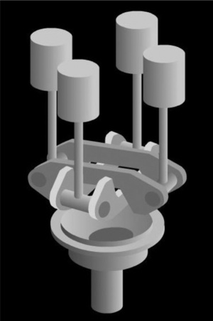
There are three main layouts of modern Stirling machines-so-called alpha, beta and gamma configurations. Fig. 18.6 shows a ‘V’ type alpha single-acting engine, which has two separate cylinders with pistons. Both the pistons are used to produce work from the engine. When using a conventional crank-drive mechanism the phase-angle in the motion of pistons is equal to the angle between the axes of cylinders, hence the cylinders are arranged at an angle of 90-120 degrees. An alpha engine can be designed to be a double-acting machine, in which the compression space of each cylinder is connected through the channels of the heat exchangers to the expansion space of the adjacent cylinder (see Fig. 18.7). Such configuration allows nearly double the power output for the same swept-volume of cylinders.
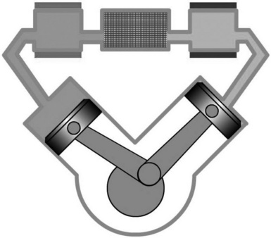

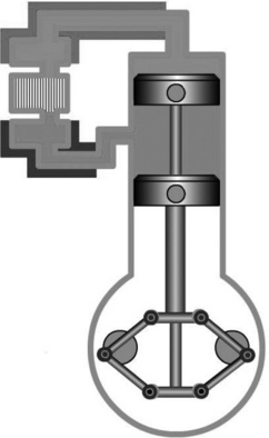
Figure 18.8 presents a general scheme of the beta-type Stirling engine in which two pistons are installed in a single cylinder. The top piston is not used to produce useful work and its only function is to control the flow of the working fluid from the compression to the expansion space and vice-versa and this piston is called a displacer. The useful work in the cycle is produced by the second piston which is called a power piston. Figure 18.8 shows one of the drive mechanisms used in such engine configurations, which is called a rhombic drive. This mechanism allows an ideal balance of dynamic forces to be achieved and takes the forces from the sides of the pistons. This results in reducing the wear of the sealing and the guiding piston rings. An ideal dynamic balancing also eliminates vibration during the operation of the engine.
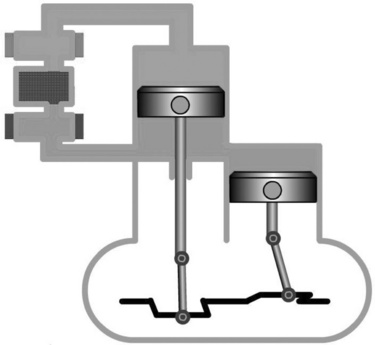
Finally, Fig. 18.9 shows the gamma configuration engine in which the compression space is split into two parts. The first part is located in the ‘hot’ cylinder under the displacer and the second part is located above the power piston in the ‘cold’ cylinder. Both the parts are connected to each other by channels made in the casing of the cylinders or by pipes.
The design configurations of Stirling engines described above have kinematical drive mechanisms. Figure 18.10 demonstrates the general concept of a free-piston Stirling engine. In this concept the engine does not have a kinematical drive mechanism. The engine is usually of a beta or gamma type with a displacer and piston in a single cylinder and operates as a thermal auto-oscillating system. Pistons perform reciprocating motions, which are in fact forced oscillations caused by the varying pressure of the working fluid in the working spaces of the engine and the forces from mechanical or gas springs. The power piston is a ‘rotor’ of a linear alternator. Its reciprocating motion in the stator generates electrical power.
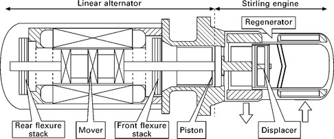
18.10 A general scheme of a free-piston Stirling engine (schematic courtesy of ENATEC Micro Cogen B.V. [11]).
18.3 Product development in the micro and small combined heat and power (CHP) market
Micro- and small-CHP is essentially the scaling of the CHP principal for use in single/small groups of domestic dwellings or small commercial properties. These smaller units are led by heat demand for space heating or hot water, with electricity generated as a by-product, the opposite of most large-scale CHP plants. hence, they are designed as replacements for conventional central heating units. The electricity produced is used within the household with any excess potentially exported to the grid. Currently, the technology of such units is still in its relative infancy, along with their deployment. The main benefit of micro-CHP is the primary energy savings from the elimination of electrical transmission losses and high operating efficiency of the system. This could bring considerable savings in fuel usage, emissions and energy bills.
A number of technologies are under development for this application, including small external (e.g. Stirling and Rankine Cycle) and internal combustion engines (usually these are four-stroke spark ignition gas engines). For the associated final product to be successful, it must prove appropriate for the market. This includes such factors as cost, capacity, heat/power ratio, efficiency, reliability, size, noise, etc. The following is a brief summary of the analysis of the technology status within the sector.
18.3.1 Rankine cycle micro combined heat and power (MCHP)
The Rankine cycle is based on external combustion and characterised by the working fluid undergoing a phase change (from liquid to gas) which can be utilised to achieve high power densities. The most familiar Rankine engine is the steam engine where water is boiled by an external heat source to cause an expansion and the generation of pressure which can be used to produce useful work.
MCHP production units implementing the Rankine cycle are entering the market and OTAG released the Lion Powerblock unit in Germany [1]. This is a double-acting free-piston steam engine with a linear alternator with outputs of 0.3-2 kWel and 3-16 kWth with overall efficiency of about 94%. The operating frequency is 40-75 Hz and noise level is between 48 and 54 dB. The dimensions of the MCHP is 126 mm (H) × 620 mm (D) × 830 mm (W) (see Fig. 18.11) and its weight is 195 kg.
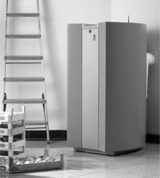
18.11 Rankine cycle Lion MCHP (photo courtesy of OTAG [1]).
Other products being developed include a 1 kWel Kingston being developed by Genlec Energetix Ltd (Capenhurst, UK). This MCHP unit is based on organic Rankine cycle with a scroll engine (see Fig. 18.12) [2] and its overall and electric efficiencies are 90 and 10%, respectively.
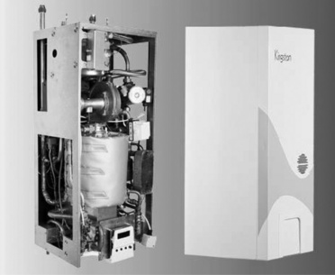
18.12 Kingston 1 kWel MCHP unit (photo courtesy of Genlec Ltd [2]).
Cogen Microsystems (Australia) has developed a Rankine cycle Cogen Micro unit based on a reciprocating steam engine (see Fig. 18.13) [3]. There are domestic (2.5 kWel, 11/22 kWth) and small commercial (10 kWel and 44 kWth) versions of Cogen CHP systems, both with an overall efficiency of 90%. Dimensions and weight of the domestic version are 870 mm (H) × 600 mm (W) × 400 mm (D) and 60 kg. The size of the commercial version is 960 mm (H) × 800 mm (W) × 600 mm (D) and its weight is 175 kg.
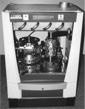
18.13 2.5 kWel Cogen Micro MCHP unit (photo courtesy of Cogen Microsystems [3]).
18.3.2 Internal combustion engine (ICE) MCHP
Currently, only the ECOWILL micro-CHP unit [4] is commercially available which is manufactured by Honda on the basis of the GE160V natural gas fuelled internal combustion engine. The engine is four stroke, water cooled single cylinder with overhead valves, with a cylinder displacement of 163 cm3. The system has 1 kWel and 2.8 kWth outputs with the option of an external auxiliary boiler. Dimensions of the system are 580 mm (W) × 380 mm (D) × 880 mm (H) and its weight is 83 kg. The overall efficiency of the system is 85.5% and power generation efficiency is 22.5%. It uses a catalytic converter along with an elaborate acoustic attenuation system to conform to the market requirements, although it might still not be suitable for indoor installation in its current configuration. In Japan a federation of three major organisations in the gas energy industry intends to sell a total of 235,000 units of ECOWILL by 2011. A variation of Ecowill, Freewatt, is sold in the USA. Freewatt has slightly greater power (1.2 kWel) and heat outputs and is sold complete with a heating system: a boiler for hot water or a furnace for hot air [5].
There are several other ICE-based CHP units, such as Baxi SenerTec Dachs (Germany) [6] and XRGI 15 of EC Power (Denmark) [7] with an electrical power output greater than 4 kWel, and these can be classified as mini-CHP units.
The Baxi Dachs Mini CHP system is based on a four stroke, water cooled single cylinder internal combustion engine, which was specially developed by Fichtel and Sachs AG (Germany). Electrical and thermal outputs are 5.5 kWel and 12.5 kWth, respectively, with the electrical and total efficiencies being 30% and 79-92%. Dimensions are 720 mm (W) × 1070 mm (D) × 1000 mm (H) and the weight is 530 kg. The service interval is 3500 hours.
XRGI 15 (see Fig. 18.14) is based on the four stroke, four cylinder water cooled Toyota gas engine. The swept volume of cylinders is 2237 cm3 and the engine is equipped with the oxidation catalyst. The electrical and thermal outputs are 6-15.2 kWel and 17-30 kWth, respectively. The total efficiency of the system is 92% with the electrical efficiency being 27-30%. Dimensions of the power system (only) are 1250 mm (H) × 750 mm (W) × 1110 mm (D) and the weight is 700 kg.
18.14 XRGI 15 Mini CHP system based on Toyota gas engine (photo courtesy of EC Power A/S [7]).
18.3.3 Stirling cycle MCHP
A number of Stirling engine-based units are being developed by Whisper Tech (New Zealand) [8], Disenco Energy (UK) [9], Microgen Engine Corporation (a consortium of the gas boiler companies Viessmann, Baxi, vaillant and Remeha with Sunpower) [10], Enatec Micro-Cogen (Netherlands) [11] and Sunmachine [12]. The nominal electrical and thermal outputs vary between 1-3 kWel and 5-36 kWth respectively.
Whispergen Mk 4/5 is shown in Fig. 18.15. This is built around a four cylinder double-acting Stirling engine with a wobble-yoke drive mechanism (see Fig. 18.16). The system has two burners: main and auxiliary. The main burner is to transfer the heat into the working fluid (nitrogen) inside the engine through heat exchangers integrated in the cylinder heads. The auxiliary burner is used to boost the heat output during large heat demand periods. Both burners are of a premix surface type. The generator is a four pole single phase induction generator. The electrical and thermal outputs are 1 kWel and 5.5-7 kWth (up to 13-14 kWth), respectively. The dimensions of the MCHP unit are 491 mm (W) × 563 mm (D) × 838 mm (H) and its dry weight is 148 kg.
18.15 1 kWel Whispergen Mk 5 MCHP unit 1 – alternator; 2 – engine; 3 – burner assembly; 4 – auxiliary burner; 5 – heat recovery heat exchanger; 6 – air fans. (scheme courtesy of Whisper Tech Ltd, New Zealand [8]).
18.16 A 'wobble-yoke' drive mechanism of a Stirling engine in Whispergen (scheme courtesy of Whisper Tech Ltd, New Zealand [8]).
E-ON in the UK supplied a relatively small number of Whispergen Mk 4 and Mk 5 MCHP units to households in the south of England and currently work is going on with manufacturing partners towards a full market roll-out of mass-produced units [13]. Efficient Home Energy Sl (or EHE, based in the Basque region of Spain), which is a joint venture between Whisper Tech Limited (a subsidiary of the New Zealand company Meridian Energy Ltd.) and the Mondragón Corporation, has commenced a large-scale production of Whispergen MCHP units for the EU market (exclusive UK) [14].
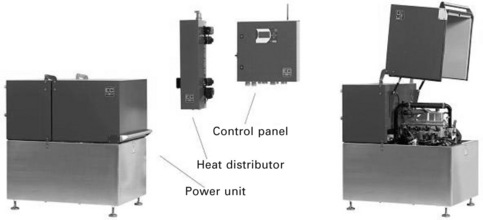
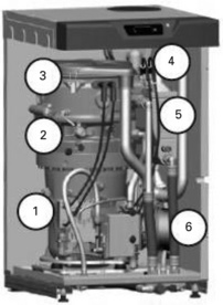
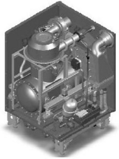
A 3 kWel MCHP unit from DISENCO is still in the development stage and little information on the technical specification is available on this product. Figure 18.17 shows a schematic of this system which has approximately the same dimensions as a Whispergen (the size of a domestic dish washer) and is built around a single cylinder beta-type Stirling engine which uses helium as a working fluid and runs at a speed of 3000 rpm. The engine used in this MCHP was derived from the engine developed by Sigma Elektroteknisk (Norway). In order to deliver 3 kWel output, the engine should be pressurised to about 70-80 bar. A proposed thermal output is 15-18 kWth (up to 30 kWth in conjunction with a thermal storage) which makes the overall efficiency of the system 90%. Figure 18.18 schematically shows components of this MCHP unit.
18.17 A schematic of 3 kWel MCHP appliance (scheme courtesy of DISENCO [9]).
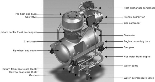
18.18 Components of 3 kWel MCHP (scheme courtesy of DISENCO [9]).
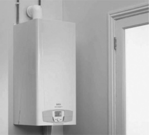
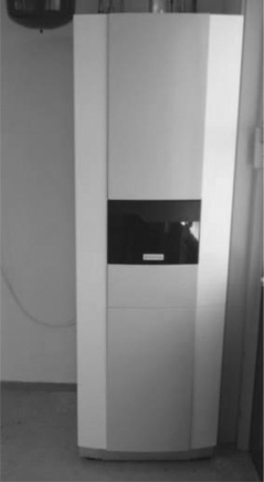
The Microgen MCHP unit is built on the basis of the extensively modified free-piston Stirling engine, which was originally designed by SUNPOWER Inc (USA), and it has a 1 kWel output [3] (see Fig. 18.19). Field trial results were encouraging, with the demonstration of net electrical efficiencies of over 15% in conjunction with an overall efficiency of 90%. Figure 18.20 demonstrates the wall-mounted Baxi Ecogen MCHP system [15] built around Microgen’s free-piston Stirling engine. The thermal output is 6-6.5 kWth (up to 24 kWth with an auxiliary burner), its dimensions are 920 mm (H) × 426 mm (W) × 425 mm (D) and the weight is 115 kg. The overall efficiency of the system is about 98% or greater (in condensing mode).
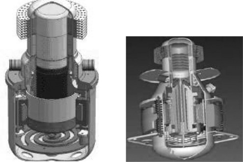
18.19 A 1 kWel free-piston Stirling engine from Microgen (UK): the scheme on the right shows the engine with installed counter-weight dynamic balancing system (schemes courtesy of Microgen Engine Corporation [10]).
Enatec, in collaboration with Rinnai (Japan), Bosch Thermotechnik (Germany), Merloni TermoSanitari (Italy), plan to carry out Europe-wide field tests of their MCHP appliance. The system is built around a modification of a 1 kWel free-piston Stirling engine originally developed by Infinia Corporation (USA) (see Fig. 18.21). Enatec is developing two versions of the MCHP system also called HRe boilers (see Fig. 18.22), one of which has a built-in heat storage tank. The thermal output is 4-35 kWth (when auxiliary burner is on), the overall efficiency of the system is > 98 in condensing mode.
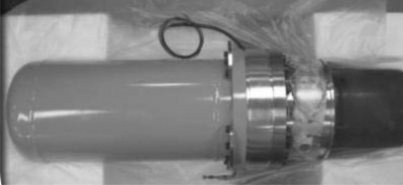
18.21 1 kWel free-piston Stirling engine used in Enatec MCHP unit (photo courtesy of ENATEC Micro Cogen B.V. [11]).
18.22 Enatec 1 kWel MCHP unit; the unit has built-in heat storage tank (photo courtesy of ENATEC Micro Cogen B.V. [11]).
Finally, a 3 kWel Stirling engine MCHP unit is being built and sold by Sunmachine GmbH (Germany). It is built around a gamma (or alpha)-type Stirling engine with a wood pellet burner. The system is equipped with a 50 l-wood pellet storage tank. The electrical and thermal outputs are 1.7-3 kWel and 6.5-10.5 kWth. Electrical and overall efficiencies are 20% and > 85%, respectively. Dimensions of this wood pellet MCHP system are 1160 mm (D) × 760 mm (W) × 1590 mm (H) and its weight is 410 kg.
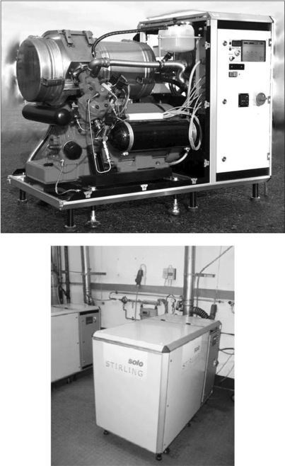
There is also the SOLO V161 Stirling CHP system (see Fig. 18.23) which was commercially available in Europe a few years ago [16]. This unit was produced by Stirling Systems GmbH and had 2-9.5 kWel and 8-26 kWth electrical and thermal power outputs, respectively. The SOLO V161 Stirling CHP was used for small commercial applications. The system was built around an alpha (V-type) Stirling engine which uses helium as a working fluid. The crankcase of the engine was unpressurised and separated from the internal gas circuit using special rod seals.
18.4 Overview of the method for estimation of economical and environmental benefits from deployment of micro combined heat and power (MCHP) technology in buildings
The method used for estimation of benefits from deployment of MCHP is described in detail in [17]. The micro- or small-CHP systems are located within or close to the property which utilises the electricity generated, with the recovered heat used to provide space heating and domestic hot water. A grid connection offers the possibility of frequency synchronisation with electricity import/export, should power demand not match the generation of the unit. The MCHP is usually developed as a drop-in replacement for the conventional hydronic central heating boiler.
The potential direct benefits of the system are economy for the consumer, savings in primary energy and reduced emissions. The micro-CHP system generates electricity from the fuel, source (mainly natural gas, but also biofuels and diesel or heating oils can be used) with a high overall efficiency due to the heat recovery system. From the differential in price between electricity and fuel, noticeable savings can be made. Also, with the appropriate metering and trading arrangements in place, excess generation can be exported back to the grid for which the consumer would be compensated. Due to the high operating efficiency of around 90%, compared with the 40% of the national electricity supply, the system results in considerable savings in primary energy and resources. From the savings in primary energy, which currently are fossil fuels, there are reduced greenhouse gas emissions. The magnitude of these benefits depends greatly on the deployment scenario, with the greatest gain achieved when the CHP system provides the maximum feasible amount of the thermal and electrical demands. Therefore, the system must suit the situation in which it is employed. The numerous factors involved include the following:
• electrical and thermal demand profiles which depend on climatic conditions; occupancy size and pattern; dwelling type and house fabric details; equipment used and attitude towards energy use
• the design of the MCHP system which can be specified by its capacity, heat/power ratio, efficiency and performance characteristics, thermal storage used (type, size, efficiency), electrical stores (type, size, efficiency); heat delivery system and control system and regime
• differential in fuel and grid electricity prices, emission factors of fuel and grid electricity; electricity export tariff
Due to the vast number of variables involved, it is very complex to make generalised predictions about the local economic and environmental impact of installing a micro-CHP unit. A number of previous papers have already attempted to model the effects of different micro-CHP units. Thus Newborough assessed the benefits of using a generalised MCHP system without referring to a specific technology [18]. Peacock and Newborough analysed the effect of 1 kWel Stirling engine and 1- and 3 kWel fuel cell MCHP on energy flows in the UK electricity supply industry and their impact on domestic CO2 emissions based on the expected average efficiencies of the systems [19, 20]. Cockroft and Kelly compared the performance of four micro-CHP technologies based on an air-source heat pump, fuel cell, Stirling engine and internal combustion engine using general performance characteristics of the above, such as average efficiencies and heat-to-power ratio [21]. Hawkes and Leach highlighted the importance of temporal precision in describing heat and power demand date when assessing CO2 emission reductions with implementation of MCHP systems [22]. According to their investigations, economic and environmental benefits can be considerably overestimated through use of coarse data. This is due to the averaging effects which ignore the significance of peaks and troughs in demand and their effects on energy import/export. However, the calculations in the above publications were performed using only averaged values of the efficiency of MCHP units. Peackock and Newborough attempted to take into account simplified dynamic characteristics of a Stirling engine MCHP during the start-up and shut-down processes [23].
In this chapter it is proposed to predict economic and ecological benefits using the experimental performance maps of the MCHP in various scenarios in the modelling process. This approach is demonstrated using the Whispergen Mk 3 MCHP as an example. First, in order to assess the various competing MCHP technologies, suitable heat and electricity demand profiles in dwellings must be quantified. As the unit is designed for use within a single dwelling, it will be subject to large fluctuations in both electrical and thermal loads, as well as their concurrency, due to the transient nature of a household’s energy requirements. Then, to evaluate the performance of the unit, a spreadsheet model of the hydronic heating system was constructed with the use of the developed daily heat and electrical loadings for weekdays and weekends for different heat demand bands.
18.5 Heat demand modelling
In the domestic sector, the average annual demand amounts to approximately 17 MWht and 4.6 MWhe of thermal and electrical energy, respectively [18]. This gives an annual heat-to-power ratio of 3.7. However, these are subject to significant variations dependent on a number of factors with little direct correlation to dwelling size. This makes it difficult to define a ‘typical home’ for the investigation from which savings predictions can be applied to the UK’s housing stock as a whole. For the purposes of these investigations, specific scenarios have been defined, based on common UK ‘ components’.
Due to the seasonal variations in household demand, the performance over a year has been calculated by producing daily profiles typical of each month of the year. The results from each of these profiles have then been weighted accordingly and combined to produce an overall picture. To ensure sufficient precision, the modelling procedure for this study have been event based, building up the demand profile on a 1 min time base from predicted events and operation of equipment.
The proposed scenarios are based on the type of house that might be most likely to install a micro-CHP unit. This was perceived to be a reasonably modern, well insulated property where the occupants have an interest in the environment and energy saving measures. From statistics produced by the Office of the Deputy Prime Minister (ODPM) in 2004, the most common type of housing was semi-detached (33% of the total housing stock) and this forms the basis of the scenario investigated for two storey semi-detached dwelling with a footprint of 64 m2. The size of the dwelling is based on national averages in 2003 for housing of that type [24]. Trends in house size show significant downsizing has occurred over the last few decades and this is predicted to continue. It was assumed in modelling that the house is occupied by a medium-sized family, consisting of two middle age adults and two children, with a typical full-time work and schooling occupancy pattern as defined in Table 18.1.
Table 18.1
Occupancy pattern for modelling procedure
| Day | Active occupancy periods |
| Weekdays Monday–Friday | 07:00–08:00 18:00–23:00 |
| Weekend Saturday–Sunday | 09:00–23:00 |
| Total occupied time/week | 58 hours |
The household thermal demand consists of three components [18]:
• Space heating-supplied by the central heating system with extreme seasonal variation, dependent on climatic conditions, dwelling design, heat delivery mechanism, occupancy patterns and perception of comfort.
• Domestic hot water-mainly supplied by the central heating system, but sometimes by electric auxiliary heaters. Little variation with season, but dependent on household appliances, occupants’ attitude to energy use, occupancy size and occupancy pattern.
• Cooking-supplied by number of appliances which may be fuelled by different fuels. Slight variation with season but dependent on cooking appliances, occupants’ attitude to energy use, occupancy size and occupancy pattern.
In this analysis, in order to characterise the thermal requirements of the proposed scenario, the following factors are included in the modelling process:
• The house is sited in the south east of England, where the Whispergen units are being initially installed. The house’s front faces south with a set of double glazed windows installed on the main south and north- facing walls. There are four vinyl windows in each of two main walls with 1 m × 0.91 m and 2 m × 0.91 m dimensions and a 13 mm air gap. The interior wall has a finish made of 100 mm bricks and the house has a gypsum board ceiling and wooden floor. Thermal performance is in line with Part L of the 2000 building regulations [25].
• Internal design temperature is 21 °C.
• The house has a conventional hydronic central heating system consisting of a gas-fired central non-condensing boiler (h = 0.8) supplying a network of appropriately sized radiators and 150 litre hot water storage cylinder.
• Domestic hot water is supplied entirely from the hot water cylinder with appliances including hot fill washing machine, cold fill automatic dishwasher, standard shower, bath and washbasins.
• Cooking is with the use of gas-fired hobs, oven and grill supplemented by an electric microwave, kettle and toaster.
18.5.1 Space heating
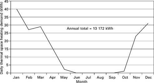
In order to calculate the space heating requirements of the dwellings throughout the year, a model was constructed in ‘Hot 2XP’, a program developed by the CANMET Energy Technology Centre [26] to analyse energy flows within buildings. Taking into account all the appropriate thermal gains (solar, occupants, equipment, cooking), building details and historical weather data, the variations in space heating requirements have been predicted as illustrated in Fig. 18.24. As can be seen, there is a significant variation between the months with no supplementary heating required during the summer months June to September and annual heat demand is 13,172 kWh.
The program also calculates the required size of space heating system, based on the maximum rate of heat loss. The result for the semi-detached house model was 5 kWth. This corresponds to the combined thermal output of the radiators when operating, fully open, at their specified supply and return temperatures, i.e. the magnitude of the maximum instantaneous thermal demand from the space heating system. The Whispergen Mk 3 unit has a thermal output of approximately 6 kWth which meets the heat demand in the semi-detached house.
The conventional control system of a central heating system consists of a ‘time led’ operation, with defined periods coinciding with the occupancy, between which the system follows the heat demand within the property. The space heating demand is monitored by a simple bi-metallic thermostat positioned within the property. This leads to a profile with a heat-up period and cycling once the design temperature has been reached. The magnitude of the demand is varied depending on the positions of the individual radiator valves. A common energy saving addition to the system is thermostatic radiator valves (TRVs) which automatically modulate the output of individual radiators to match the requirement of the room. The majority use the principal of thermal expansion with an appropriate mechanism to steadily close the valve as the room approaches the desired temperature. They save energy by reducing the overheating of individual rooms and, if the boiler is capable of modulating its output, reducing the cycling of the boiler. In terms of the demand profile, TRVs lead to a shape illustrated in Fig. 18.25. The exact proportions and shape depend on a number of factors, such as the initial room temperature, the building’s thermal inertia, performance of the TRVs and current climatic conditions. In particular, the steady state will be subject to fluctuating thermal gains, e.g. solar or occupancy, and this will vary with the control system’s response to these. However, to simplify the modelling, the profile may be split into two stages as shown in Fig. 18.26: the initial heating period where the design temperature is reached followed by the steady state where the temperature is maintained.

18.25 Idealised space heating demand profile with TRVs. 1-The heat up period where the valves are fully open and the system operates at maximum power; 2-The valves start to close, reducing thermal power, as the temperature approaches the set point; 3-Steady state reached where thermal power balances heat loss from building.
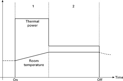
18.26 Space heating demand profile for modelling purposes. 1 –Heat up period where valves are fully open and system operates atmaximum power; 2 – Steady state reached where thermal power balances heat loss from building.
As the occupancy pattern is based around full-time work, the dwelling will be empty for a significant period in the middle of the day during the week; therefore there will be two timed periods of operation. At the weekend, there is a less prescribed pattern with the likelihood that the property is occupied all day, resulting in a single long period of operation. The occupied periods correspond to the steady state part of the profile (area 2) in Fig. 18.26, when the design temperature is maintained. Therefore the system will come into operation earlier to actually raise the temperature to that required. Taking into account the marked difference between weekdays and the weekend, a representative profile for each type of day is required for each month. However, due to the symmetry of variation throughout the year, months with similar thermal demands can be grouped together so reducing the number of profiles required (see Table 18.2). Appropriate banding is shown in Fig. 18.27, which breaks the year into five different heating categories.
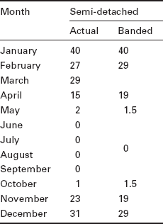
This grouping requires ten separate daily profiles for the dwelling. These are generated using the occupancy pattern in conjunction with the banded daily requirements and output ratings of the systems from the CANMET program. The results demonstrate there is a large variation in the steady state power required from the central heating boiler.
18.5.2 Domestic hot water
An average person in the UK uses 49 litres of hot water per day, with little seasonal variation [27]. The actual consumption is linked to the composition of the household, e.g. single or multiple occupiers, over or under 60 years of age, young or dependent children. It also depends on the equipment used and their specification, e.g. automatic washing machine, high flow rate power shower, etc.
For the prescribed scenario of a couple with two dependent children utilising an automatic dishwasher, the average daily consumption rises slightly to 50 litres per person, resulting in a household consumption of 200 litres per day. This requires an annual thermal input of 4245 kWhth. As stated, this is supplied from the hot water storage cylinder within the gas-fired central heating system.
This thermal storage method uses a heat exchanger within the cylinder to transfer heat from the closed loop boiler circuit to the surrounding water in the cylinder when the central heating system is active. This is regulated by a thermostat on the tank which restricts the maximum temperature to 60 °C. Domestic hot water is drawn off the top of the cylinder, as required, which is then refilled from the cold header tank. This system effectively creates a buffer between demand and generation, providing hot water outside the operation of the central space heating system. The size of the buffer, i.e. storage cylinder, is governed by the overall system design and the demands placed upon it. The capacity specified in the scenario is 150 litres which is around average with a capacity of 8.73 kWhth, assuming an increase of the temperature of water from 10 °C in mains to 60 °C in the cylinder. This part of the thermal demand forms the base load for the system as it demonstrates little seasonal variation, therefore, only two daily profiles are required; weekday and weekend. The same profiles will also be applied to both scenarios. To form the profiles using an event-based method, the uses and their requirements must be identified along with an appropriate schedule.
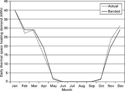
The majority of hot water is required for one of five main activities. These are summarised in Table 18.3 along with their proposed characteristics for the purpose of modelling. There are obviously further miscellaneous uses, e.g. car washing, which are not daily and make them difficult to integrate into the model. However, they are relatively small and can be eliminated without affecting the accuracy of the model.
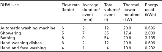
The schedule and frequency of the above events can be calculated by considering the activities of a household throughout the day and the estimated daily usage of 200 litres. The two proposed profiles are shown in Fig. 18.28. As expected, the weekend profile is more distributed throughout the day whilst the weekday profile shows concentrations around the limited occupancy periods.
18.5.3 Cooking
Cooking requires high temperature inputs that are not supplied by a central heating system. However, the heat produced does contribute to the thermal gains of the property, slightly reducing the auxiliary space heating required. If the thermal loads due to cooking are met by electricity, the electrical demand profile will demonstrate large fluctuations due to the high power requirements of the thermal devices. As the main cooking appliances in the scenarios are gas-fired, the effects on the electricity profile will be less dramatic.
18.6 Electrical demand
It was assumed in the modelling process that the household electrical demand consists of three types of load:
• Base load-a constant load of about 100 We due to the standby power consumption of most electrical goods, plus the cyclic load from refrigeration devices. This is present all day, throughout the year, with little variance.
• Biased load-a load that occurs on most days at similar or predictable times, e.g. lighting, television, cooking appliances. These arise through external influences or habitual behaviour.
• Elective load-a load operated primarily at the occupier’s discretion, e.g. washing machine, PC. These are harder to predict due to their more irregular nature.
The daily electrical profile is made up of a combination of these loads, with the peaks occurring during periods of coincidence. The profile as a whole demonstrates little seasonal variation, except with changes in lighting periods and seasonal equipment. Taking the average annual electricity consumption at 4.6 MWhel [18], the daily usage is approximately 12.6 kWhel.
As with the domestic hot water, to form the profiles using an event-based method, the electrical loads and their characteristics must be identified along with an appropriate schedule. Recent years have seen significant improvements in the efficiency of household appliances. With increased public awareness through advertising and literature on the subject, ‘A’ rated appliances are becoming the standard for new and replacement purchases. From previous research on the subject regarding ownership and energy consumption trends [28, 29], the details of the appliances to be included in the model, along with their usage patterns and consumption, were compiled and these are shown in Table 18.4. This table contains only a certain number of the electrical loads present within a household. However, these were thought to be the most influential for the investigation due to either their peak power or usage pattern. In order to create the daily profiles, a suitable schedule for operation must also be created. Due to the slight seasonal variation, it was decided to use the approach adopted for the space heating profiles and generate a pair of profiles, weekday and weekend, for each of the heating categories. This still captures the variation to a suitable degree as it follows a similar symmetric variation through the year.
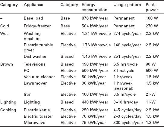
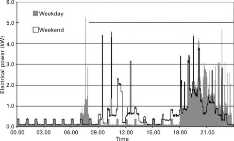
A number of electrical appliances within the household are not used daily, as becomes evident from Table 18.4. This creates problems when generating single daily profiles to be applied to extended periods. To overcome this, the operation of these non-daily loads will be evenly spread over 52 weeks to create weekday/weekend profiles to achieve an effect similar to the usage pattern prescribed. As before, the actual daily schedule was created by considering the activities of a household throughout the day and translating this using the acquired appliance information into an electrical demand profile. Examples of those generated are shown in Fig. 18.29. The weekend profile shows a more distributed load with 14.3 kWh of total and 5.35 kW of peak loads against 13.8 kWh and 4.58 kW of total and peak loads, respectively, in weekdays. However, both profiles have similar peaks in the evening due to the high concurrent use of appliances in this period.
18.7 Performance mapping
To produce a comprehensive performance map of the Whispergen Mk 3 MCHP unit, the following key areas were focused on:
• response to heat demand (start-up and run-down characteristics);
• maximum outputs (electrical and thermal);
The Whispergen Mk 3 unit has been installed within a test rig which consists of a small-scale mock-up of a conventional hydronic space heating system (theoretical output of 6 kWth) and the test rig contains a number of meters:
• Ultrasonic heat meter (Landis Gyr+ 2WR5)-measures the flow rate through the radiators and the heat supplied.
• Data logging via RS232-PC connection to CHP unit itself to log main parameters including electrical output.
• Gas meter-monitors gas consumption to calculate overall efficiency.
• Gas analyser (RBR Ecom KD)-analyses exhaust composition using heated sample system with probe placed directly in the exhaust flue of the unit.
The heat demand for the system, usually indicated by a combination of a time switch and thermostat, was simplified to a time switch which allows simulation of timed periods of demand. The variables within the rig during experiments were periods of heat demand (duration and pattern), set point temperature of hot water in Whispergen Mk 3 (60-75 °C) and position of radiator valves.
A number of experimental configurations were executed whilst monitoring the system. These have been analysed with the relevant information, figures and characteristics extracted for inclusion in the relevant following section. One of the important characteristics that affects the unit’s provision of heat and power is how fast it switches into operation after the heat demand is signalled. This is influenced by a number of factors, such as the control strategy, thermal mass of the cylinder walls and burner output; as with all external combustion engines, it must warm up before it will begin to operate. To evaluate this aspect, the thermal and electrical outputs at the start and finish from a number of cycles were examined and compared.
18.7.1 MCHP performance as a response to heat demand: start-up
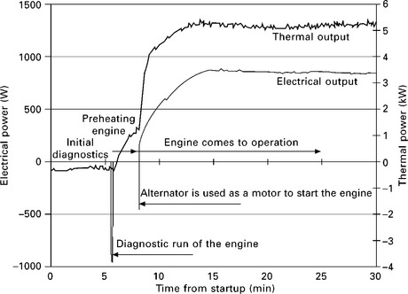
Start-up characterirics of the MCHP unit were recorded from a number of separate cycles for a 30-minute period following a heat demand signal. In all these cycles the central heating system was starting from room temperature.
The results demonstrated significant variation in the time taken to reach a semi-steady state; between 10 and 20 minutes. All of the profiles have very similar shapes and gradients, hence the variation arises from the initial delay in the system before it appears to start. The source of this delay is believed to be internal diagnostics by the control system with dependence on external variables such as the air and current central heating water temperatures. From examining a single pair of electrical and thermal profiles, distinct periods in the start-up procedure can be identified, as shown in Fig. 18.30.
18.7.2 MCHP performance as a response to heat demand: run down
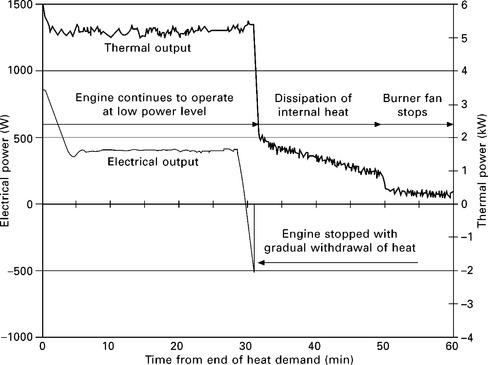
A similar comparison was made between the profiles recorded after the end of the heat demand. Governed by the control system, the unit operates on a low power level for approximately 30 minutes after the heat demand ceases. Compared with start-up, the profiles are equally consistent in terms of their shape and gradient, but much more so in regards to timing, with two shutdown procedures apparent depending on the power level prior to shutdown. Notable thermal energy is supplied after the shutdown of the engine as the heat stored within the cylinder walls is transferred to the exhaust heat exchanger by the continuing operation of the burner fan. An examination of the run-down characteristic is given in Fig. 18.31.
18.7.3 MCHP performance as a response to heat demand: maximum outputs
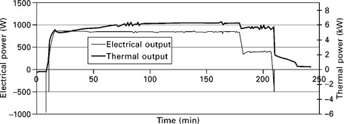
The maximum outputs were measured by operating the system at 75 °C with the radiators fully open for a three hour heat demand period. This produced the profiles shown in Fig. 18.32. The thermal power reached 80% of its maximum after 20 minutes, plateauing at approximately 6.25 kW after 2 hours while the electrical power reached its steady peak of 850 W after 20 minutes. From examination of the gas consumption, this consisted of a single burner firing rate with the variation due to the system ‘warming up’.
18.7.4 MCHP performance as a response to heat demand: modulation capabilities
As the thermal demand within the household will vary and often be less than the unit’s maximum output, it is important to analyse modulation capabilities of the system. To investigate this, two of the radiators were three-quarters closed, the set point temperature reduced to 65 °C and a two hour heat demand period programmed. This produced the profiles shown in Fig. 18.33. From these results, it becomes apparent that the unit can only operate continuously on two separate power levels. In this run, the unit operated at full power to bring the flow temperature close to that of the set point, after which it switched to a lower level. However, this still provided too much thermal energy causing the flow temperature to continue rising. This resulted in the engine switching off entirely for a 12-minute period while the temperature dropped. The pattern was then repeated when the engine restarted.
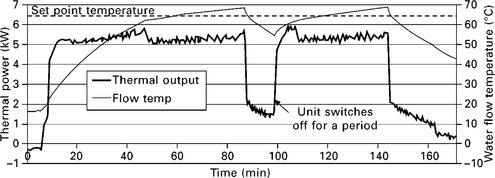
The unit is capable of little modulation, with only steady state thermal outputs of 5.3 kWth and 6.25 kWth. This will produce a high cycling rate during long periods of low thermal demand which will be detrimental to the performance of the unit.
18.7.5 Efficiency per cycle and power level efficiencies
The economic performance of the unit will be governed by both its overall efficiency and heat-to-power ratio (HPR). This is due to the significant difference in gas and electricity prices. The efficiency and HPR can be examined on two levels:
• Per cycle basis using the total output energies and gas consumption for the period. This can be used to compare modulated and non-modulated cycles.
• Power level basis using the recorded trends within a cycle. This can be used to analyse the full and part load efficiencies.
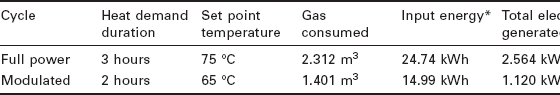
For comparison, the profiles from Figs 18.32 and 18.33 were analysed along with their gas consumption data. The results are presented in Table 18.5. The figures show a significant difference in both the efficiencies and ratios for the compared cycles. As anticipated, the modulated cycle with its engine shutdown period is nearly 10% less efficient. Also, the proportions of heat generated are greater, further decreasing the comparative economic value.
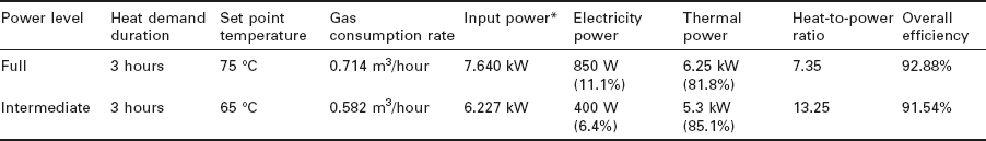
The instantaneous efficiency of the unit was analysed for the two steady state power levels, namely full and intermediate power levels. This was achieved using two 3 hour runs at 65 °C and 75 °C and their gas consumption. The data used to calculate the efficiency were taken once the outputs had stabilised. The results are shown in Table 18.6. Both power levels have high overall efficiencies of over 90% but the major difference lies in the heat- to-power ratio. This is almost doubled when the unit switches from full to intermediate power. Hence, the possible economic returns will be severely diminished if the unit operates at the intermediate power level for extended periods due to the reduced proportion of electricity produced.
18.7.6 Emissions analysis
As one of the major drivers behind micro-CHP development is the reduction of harmful gas emissions, the composition of the Whispergen’s exhaust is very important. This was investigated using the gas analyser included in the test rig. The combustion process inputs are natural gas and air. Therefore, the components of flue gas are primarily made up of compounds of oxygen, nitrogen, hydrogen and carbon. The efficiency of the combustion process can also be determined from the combustion products. This was achieved using the oxygen and/or CO2 measurement in conjunction with pre- and postcombustion gas temperatures. The calculation was performed automatically by the gas analyser. The exhaust composition and combustion efficiency was logged at two-minute intervals for a number of experimental runs. An example from a three hour run is shown in Fig. 18.34. The gas analyser relies on an electrochemical reaction for its readings and must be purged at regular intervals during continuous measurement, hence the short gaps in readings.
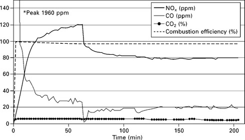
The actual amount of carbon dioxide produced depends on the type and amount of fuel burnt, hence this was a function of gas consumption rather than the burner design. For natural gas, this was 0.19 kg/kWh. Carbon monoxide is the product of incomplete fuel combustion from the lack of oxygen. As the Stirling engine design is based on continuous external combustion, which is easily optimised, the combustion process is highly efficient as indicated. This results in little formation of carbon monoxide once the process has stabilised.
The principal source of NOx emissions in natural gas appliances is the oxidation of excess atmospheric nitrogen at temperatures above 1100 °C. Modern applications require the minimisation of NOx through advanced burner design. Emissions can be greatly reduced by rapid or complete mixing of the gas/air fuel supplies and encouraging the internal recirculation of combustion products. This minimises the peak temperatures in the combustion zone. The Whispergen Mk 3 unit has peak NOx emissions of over 120 ppm. During steady state operation this level is about 80 ppm. Typical NOx emission level in conventional burners is between 110 and 150 ppm. In burners with the fully pre-mixed combustion process, the NOx emission level is reduced to 45-75 ppm whilst advanced burners, such as catalytic stabilised and catalytic, have NOx emissons less than 5-10 ppm [30].
18.8 Economic and environmental analysis
To evaluate the performance of the unit, a spreadsheet model of the hydronic heating system was constructed with the use of the daily developed heat and electrical loadings for weekdays and weekends for different heat demand bands. The mapped characteristics of the unit were applied, and the system performance calculated for each of the pairs of electrical and thermal demand profiles. The time step in the modelling process has been to one minute. This is necessary in order to make it possible to reflect the gradual increase or decrease in the thermal and electrical outputs when the engine is switched on or off. The results were weighted according to the banding strategy to form a picture of the unit’s performance over a typical year in each scenario. These were then analysed for efficiency and the anticipated economic and environmental savings of installing a micro-CHP.
In the modelling process the following physical features of the heating system were taken into account:
• Thermal inertia-As well as the thermal mass of the house and hot water cylinder, the water and associated pipe work within the heating circuits have their own mass. This affects the lag present within the system. The heat capacity of the test rig was determined by examining the rate at which the radiators heated during the experimental runs in conjunction with the thermal input and dissipation calculated. This capacity was then scaled to each scenario according to the maximum space heating output of each system. Additional thermal mass was also added to model the 5 kW heating circuit through the hot water cylinder which is not present in the test rig.
• Individual space and tank thermostats-Most heating systems contain a distribution valve which directs the hot water from the boiler to where it is needed. If no further space heating is required, all the water from the boiler is directed to the hot water cylinder and vice versa. This was included in the model along with the effects when the valve position changes, mixing standing water from one circuit with the active circuit.
• Variable heat loss-As the inside of the house heats up, the heat loss through the fabric will increase in proportion. The heat losses from the house in various seasons, at design temperature, were obtained from the CANMET program results. These were then used to model variable heat loss for each season based on the current internal and appropriate ambient temperatures.
• Standby losses from hot water cylinder-While the hot water is stored in the cylinder, an amount of heat is lost through the walls depending on the temperature of the water. This can be reduced through insulation, although not totally removed. An appropriate loss was included in the model in line with current British Standards for hot water cylinders. The effect of thermal stratification within the cylinder was also taken into account for modelling the performance of the heat exchanger.
To assess the economic benefits of the Whispergen Mk3 unit, the associated costs must be compared to the base situation of a conventional boiler with all the household electricity imported from the grid. In conjunction with the performance of the Whispergen Mk 3 unit, the most important factor is the differential between gas and electricity prices. For analysis, the standard ‘British Gas’ gas and electricity tariffs for 2005 in the London area were used. In this example, benefits from the new feed-in tariff scheme were not included in the calculations. These, along with most other tariffs, consist of two rates: a higher rate for the first x units each quarter followed by a much lower rate. To ease the costing, these were averaged out on the estimated household usage. The result was a kWh unit cost of 3p and 10.6p for gas and electricity, respectively. This leads to a significant difference which will maximise the value of the micro-CHP generation.
A further value is generated by any rebate for the export of excess electricity through the appropriate network and metering interface. The rebate per exported unit is generally significantly less than the import rate due to the embedded infrastructure costs, etc. A rate of 3p per unit was used for the analysis as an average value.
The main environmental benefit comes from reduced CO2 emissions through high efficiency of localised generation. From analysis of the electrical grid and its generation facilities, the amount of CO2 released per unit reaching the consumer can be estimated and the figure used in the calculations was 0.43 kg/kWh. A similar figure was produced for the combustion of natural gas, which was 0.19 kg/kWh. The reduction in CO2 emissions was calculated using these figures and the assumption that the electricity exported from the household was ‘CO2 free’.
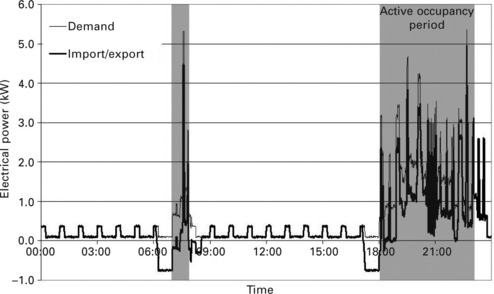
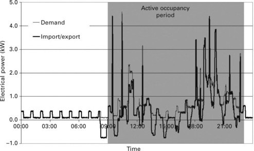
The performance of the unit is strongly related to how well it can match its thermal output to that required. The band 1 winter days had the highest rate of heat loss from the building and therefore required the most space heating input. In conjunction with the hot water cylinder, this provided a large enough thermal sink to prevent the system flow temperature from rising above that at which the Whispergen Mk 3 unit shuts down. This lead to long run times with little cycling, resulting in a high efficiency with a constant electrical output. However, simulation results demonstrate that the temperature of the water in the hot tank drops below an acceptable level. The various system temperatures for the weekday in this band are shown in Fig. 18.35. The corresponding electricity import/export profile shows mainly concurrency between generation and demand resulting in little export, maximising the value of the electricity generated. The high thermal demand also allowed the unit to operate at full power for significant periods which minimised the heat-to-power ratio. The graph illustrating the electrical distribution is shown in Fig. 18.36.
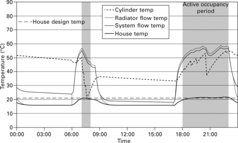
18.35 System temperatures for semi-detached heating band 1 weekday. Cylinder Temp – the average temperature of the water in the hot water tank; Radiator flow temp – the temperature of the water coming out of the radiators; System flow temp – the temperature of the water coming out the MCHP.
The economic and environmental savings are inherently dependent on duration of operation resulting in days of highest thermal demand having the largest attributable savings. In contrast, as the space heating demand decreases towards the middle of the year due to reduced heat loss through the fabric of the building, the system does not have enough thermal dissipation for the Whispergen Mk 3 to run continuously at even its intermediate power setting. This resulted in the constant cycling shown in Fig. 18.37 by the system temperatures for a mid-season weekend profile. It can be seen that the MCHP does not maintain the hot water temperature in the storage tank. The operating efficiency for this profile showed a marked 5% decrease compared to its band 1 equivalent.
The intermediate power operation also increases the heat-to-power ratio which further diminishes the savings. The corresponding electricity profile (Fig. 18.38), showed the expected import/export fluctuations, partly due to cycling but also to the reduced electricity demand during the middle of the day.
The Whispergen Mk 3 operates at flow temperatures considerably lower than a conventional boiler to maximise the efficiency of and protect the Stirling engine from overheating and therefore it would be desirable to modify the existing heating system by switching to low-temperature radiators. Conventional radiators can still be used though they are designed to operate with a higher temperature difference of ~ 50-60 °C while the Whsipergen Mk 3 provides the thermal output restricted to a temperature difference of ~ 40 °C as found in the simulation. Due to this lower temperature of the water coming out of the MCHP system, there is also restricted heat transfer in the hot water cylinder.
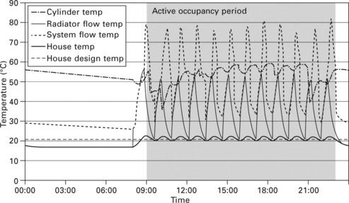
During the summer months when the need for space heating is practically removed, the unit operates periodically to heat the hot water cylinder. However, without the load sink of the space heating system and the limited transfer to the cylinder itself for the reasons above, the flow temperature quickly rises causing the unit to shut down. Therefore, the summer profiles consist of an excess number of short, intermediate power cycles resulting in relatively low overall efficiency, high heat-to-power ratio and little production of electricity. As in previously considered cases, the MCHP is not capable of maintaining the high temperature level in the storage tank. This kind of operation is shown in Fig. 18.39.

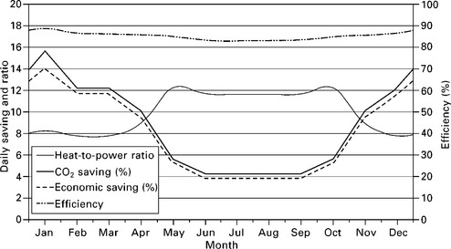
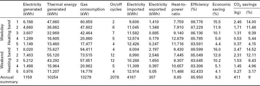
As anticipated, the annual variation in daily savings basically mirrors the thermal demand of the household, as is apparent in Fig. 18.40. Due to their origin, the CO2 and financial reductions are directly related. During the four summer months, the savings drop to a lowly 4% meaning little difference is seen between the CHP and conventional system. A similar variation profile is apparent in the unit’s efficiency, although with reduced magnitude. The lack of reasonable thermal demand-following capabilities results in an estimated total of 2078 cycles per year, averaging over five a day. This is acutely detrimental on the service interval of the unit as well as its expected life.
Over the year, the unit satisfied 16.9% of the household’s electrical requirements in response to the thermal demand. This relatively low figure illustrates the mismatch between the annual heat-to-power ratios of 8.85 for the unit and 2.04 for the demand. The ratio for the modelled demand is lower than the average but it is typical for the modelled modern house due to the trends in house design and electrical appliance ownership. Of the electricity generated, 26.5% was exported to the grid. This indicates a reasonable level of concurrency between thermal and suitable electrical demands to absorb the electricity generated.
The annual savings amount to 9% and 9.3% in monetary and CO2 terms respectively. The household was modelled using the ten representative heat/power profiles analysed above, providing simulation results on a per day basis. These are summarised in Table 18.7 along with a weighted annual summation.
One of the major problems with this particular MCHP system (the Whispergen Mk 3) was its small range of thermal modulation. Modern high efficiency boilers commonly have continuous modulation capabilities with a ratio of 1:3. This is compared to a ratio of 1:1.2 with only two discrete values available for the Whispergen Mk 3 unit. Excessive cycling occurs as a result.
The operation of the Whispergen Mk 3 unit could be improved by adapting the existing heat delivery systems within the household to greater suit the characteristics of the unit. This could be achieved in a number of ways, such as the use of larger conventional radiators, taking into account the lower temperature differential when calculating the output, or forced convection to increase the radiator heat dissipation via fans, although this may produce an undesirable environment in terms of noise and excessive air motion. A thermal storage system for space heating could be used as well for the domestic hot water, so allowing long, highly efficient periods of operation [31].
Most importantly, it should be highlighted that the above relatively conservative results were obtained without taking into about the new feed-in tariff scheme which is currently in place (£0.1 for each kWhel for cogenerated power and an additional £0.03 for each kWhel exported to the grid). If this new scheme is taken into account, then savings produced by a MCHP appliance will increase significantly.
Finally, the system’s operation on ‘ intermediate power’ level may have reduced the value of the electrical efficiency in these tests on the Mk 3 unit. The intermediate power mode is disabled in the currently available Mk 5 version of the unit and the engine operates at full power and only switches on and off. Further, the Mk 5 version of the MCHP is equipped with an auxiliary burner to meet higher levels of heat demand and utilises a low emission, pre-mix, steel mesh burner with NOx levels in the 20-40 ppm range.
18.9 References
1. 17 September OTAG Vertriebs GmbH & Co.KG. http://www.otag.de, 2010
2. 12 September Energetix Group plc. http://www.energetixgroup.com, 2010
3. 15 September Cogen Microsystems. http://www.cogenmicro.com, 2010
4. 12 December HONDA. http://www.hondanews.com, 2008
5. 16 August. http://www.freewatt.com, 2010
6. 14 August Baxi-SenerTec UK. www.baxitech.co.uk, 2010
7. 15 September EC Power A/S. www.ecpower.co.uk, 2010
8. 29 April Whisper Tech Ltd. http://www.whispergen.com/, 2010
9. 12 July DISENCO ENERGY plc. http://www.disenco.com, 2010
10. 12 May Microgen Engine Corporation. http://www.microgen-engine.com, 2010
11. 12 September ENATEC Micro Cogen b.v. http://www.enatec.com, 2010
12. 16 August. http://www.sunmachine.com, 2009
13. E.ON, 12 December. http://www.eonenergy.com/At-Home/Products/Technology-And-Initiatives/WhisperGen.htm, 2008
14. 16August. http://www.ehe.eu, 2010
15. 16 August. http://www.baxi.co.uk/ecogen, 2010
16. 12 December Stirling Engine Systems GmbH. http://www.stirling-engine.de/engl, 2008
17. Veitch, D.C.G., Mahkamov, K. Assessment of economical and ecological benefits of using a Stirling domestic CHP unit based on its experimental performance. Proceedings of the Institution of Mechanical Engineers, Part A. Journal of Power and Energy. 2009; 223(7):783–798.
18. Newborough, M. Assessing the benefits of implementing micro-CHP systems in the UK. Proceedings of Institute of Mechanical Engineers, Part A: Journal of Power and Energy. 2004; 218(4):203–218.
19. Peacock, A.D., Newborough, M. Impact of micro-combined heat-and-power systems on energy flows in the UK electricity supply industry. Energy. 2006; 31(12):1804–1818.
20. Newborough, M., Peacock, A.D. Impact of micro-CHP systems on domestic CO2 emissions. Applied Thermal Engineering. 2005; 25(17–18):2653–2676.
21. Cockroft, J., Kelly, N. A comparative assessment of future heat and power sources for the UK domestic sector. Energy Conversion and Management. 2006; 47(15–16):2349–2360.
22. Hawkes, A., Leach, M. Impacts of temporal precision in optimisation modelling of micro-combined heat and power. Energy. 2005; 30(10):1759–1779.
23. Peacock, A.D., Newborough, M. Controlling micro-CHP systems to modulate electrical load profiles. Energy. 2007; 32(7):1093–1103.
24. 29 April. http://www.planningportal.gov.uk, 2008
25. 29 April. http://www.rics.org, 2008
26. 29 April. http://www.sbc.nrcan.gc.ca/software_and_tools/hot2xp_e.asp, 2008
27. Estimates of hot water consumption from the 1998 EFUS. Implications for the modelling of fuel poverty in England. A summary report presenting data from the 1998 EFUS produced by the BRE Housing Centre on behalf of DTI and DEFRA., 2005.
28. Newborough, M., Augood, P. Demand-side management opportunities for the UK domestic sector. Generation, Transmission and Distribution, IEE Proceedings. 1999; 146(3):283–293.
29. Fawcett, T., Lane, K., Boardman, B., Lower carbon futures for European households. Environmental Change Institute, Oxford University http://www.eci.ox.ac.uk/research/energy/lcfpublications.php, 2008.
30. Joynt, B., Wu, S., Nitrogen oxide emissions standards for domestic gas appliances Chapter 5, February 2000 Environment Australia. http://www.environment.gov.au/atmosphere/airquality/publications/residential/, 2008
31. Haeseldonckx, D., Peeters, L., Helsen, L., D’Haeseleer, W. The impact of thermal storage on the operational behavior of residential CHP facilities and the overall CO2 emissions. Renewable and Sustainable Energy Reviews. 2007; 11(6):1227–1243.