
Small and micro combined heat and power (CHP) systems for the food and beverage processing industries
Abstract:
This chapter provides an overview of CHP energy technologies for the food and beverage processing industries on the small and micro scale. The chapter starts by providing the right context in terms of key energy demand properties of food processing sites as well as with techniques of energy integration. next it proceeds to describe the key small- and micro- CHP technologies, starting from the established ones and continuing further with experimental and developing technologies represented by fuel cells. The chapter concludes with a summary of the future trends and information for further reading.
16.1 Introduction
The world population is growing fast and this imposes a number of global challenges, mainly the simultaneous increase in the demands for food, water, and waste management. Resource demands are not only rising, but also feature strong interactions competing for energy.
Food processing refers to the activities converting raw food materials to final consumable products. Foods are processed for the purpose of enhancing quality, taste, nutritional value, as well as shelf life. Processing methods include cooking, preserving, packaging, storage and distribution. One of the main features of the food industry is that, besides the target products, certain amounts of waste are released, most of them of organic composition. Therefore, the food industry has the unique property to simultaneously impose energy demands and potentially offer a number of streams from which energy can be generated. Therefore efficient supply and use of energy in the food industry, including efficient combinations of waste management and energy generation, are of paramount importance to give the food industry a competitive edge. A very important aspect of energy supply for the food industry is the need for local generation, especially for smaller-scale plants, thus avoiding potentially costly energy carrier transport operations, and resulting in a ‘distributed generation’ architecture.
The objectives of this chapter are to first address the basic concepts and issues concerning CHP systems in the food industry, followed by a more in-depth coverage of the issues of energy supply and integration of smaller- scale CHP technologies.
16.2 Food processing and energy requirements - examples for specific food and drink industries
Many food companies are significant energy users due to the need for heating and cooling of their products during manufacture and storage. The energy for heating is normally consumed as thermal energy from the combustion of fossil fuels to generate steam and hot water. Cooling and refrigeration generally consume electricity, which also powers other equipment, lighting, ventilation, etc. Within the dairy industry, the split of thermal energy consumption is typically around 80% for heating and 20% for cooling (Elkin and Stevens, 2008).
There are various processes needed for food and beverage production. The following sections present a brief overview of some of them from the point of view of energy demand and supply. The food sector, including slaughterhouses, contributes to the energy consumption by industry. For example, in Flanders, the food sector consumes about 2% of the total industrial energy (Genné and Derden, 2008). In the UK the food industry uses about 126 TWh/y which is equivalent to 14% of the energy consumed by UK businesses (Elkin and Stevens, 2008; DEFRA, 2006).
16.2.1 Sugar production
An extended discussion of energy and water management in the sugar industry was provided by Urbaniec and Klemeš (2008). The authors point out that in recent decades, the world output of sugar has tended to exceed the demand, causing a decrease in investments in new sugar factories. For economic and environmental reasons, however, there is a constant need for reconstruction of sugar factories - mostly to increase the production rate and reduce energy waste and emissions. In order to obtain the main product, that is, crystalline sugar with a negligible water content, water must be separated thermally with minimum energy expenditure determined by its specific heat of evaporation of 2258 kJ or 627 kWh per 1 kg water at atmospheric pressure. A factory example has been provided with processing capacity of 4800 t beet per day. The specific fuel consumption is about 3.40 kg oil equivalent (at 41 MJ/kg) per 100 kg beet, resulting in a total energy consumption of 2278 MW for the total site.
16.2.2 Meat processing
At most slaughterhouses, the largest part of electricity demand (50-65%) comes from refrigeration operations. The consumption of energy in slaughterhouses is also closely connected to the use of hot water, whose temperature is usually activity dependent. Various process steps require the availability of water at lower or elevated temperatures (4-7 °C, 40 °C, 55 °C and 90 °C) (Genne and Derden, 2008). Refrigerated areas include chills, freezers and cold stores, which entail electricity consumption even during non-production periods.
The slaughtering industry can be subcategorised on the basis of the type of animals that are slaughtered: large animals (e.g., pigs, cattle, horses and sheep) and small livestock (e.g., poultry). Most slaughterhouses are small- and medium-sized enterprises (SMEs) and have a labour-intensive character. The electricity consumption varies widely and is very plant specific, e.g. 7-60 kWh/pig, 20-310 kWh/cattle, 0.4—1.2 kWh/piece of poultry. The varying use of external energy (fuel) to heat water (20-90%) and pig scalding and singeing (50-75%) are other key issues.
16.2.3 Processing of agricultural crops
Small-to medium-scale plants for production of refined sunflower oil (Klemeš et al., 1998) feature two types of heating utilities, steam/dowtherm and steam/water totalling about 1 MW of use, and two cooling utilities, cooling water and ice water totalling about 0.8 MW. The same source reports similar utility demands also for sites extracting raw sunflower oil, where the added complication is the operation using a volatile and flammable extraction agent.
An example from crystalline glucose production (Klemeš et al., 1998) indicates utility demands after heat integration of about 2.5-3 MW for steam and 0.7 MW for cooling water. Operating plants in this process widely use vapours bleeding from a multiple-stage evaporation system for concentrating the water-glucose solution.
A further example is given by a case study of a Whisky Distillery (Kemp, 2007; CADDET, 1994). This reports a set of energy demands split among power (12 MW), heating (40-50 MW) and cooling (15-20 MW).
16.3 Heat and power integration of food total sites
Energy recovery is not only an energy supply or CHP issue, it is also important for two reasons. First, applying energy recovery improves the performance of the concerned processes, reducing the utility requirements and thus making the task of energy resource supply easier. Second, advanced CHP technologies for supplying utilities make extensive use of energy recovery and heat integration (Klemeš et al, 2010).
As a whole, food processing is characterised by relatively low temperatures of process streams (rarely above 120-140 °C), by small numbers of hot streams (some with varying final temperatures, for example secondary condensate of multiple-stage evaporation systems), by low boiling point elevation of food solutions, by intensive deposition of scale in evaporator and recovery systems, and by seasonal performance. The application of heat integration is hindered by some specific technological and design requirements, for example direct steam heating, difficulties in cleaning heat exchanger surfaces and high utility temperatures.
16.3.1 Basic heat integration
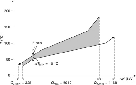
In the late 1970s the push for better industrial energy efficiency led to the development by Linnhoff et al. (1982) of the basis of pinch technology - now considered the cornerstone of heat integration. The discovery of the heat recovery pinch was a critical step in the development of heat exchanger network (HEN) synthesis. The methodology has been further developed and the most recent state-of-the-art has been presented elsewhere (Klemeš et al., 2010). The main idea behind the formulated HEN design procedure was to obtain, prior to the core design steps, guidelines and targets for HEN performance. This procedure is based on established thermodynamic theory. The hot and cold streams for the process under consideration are combined to yield a hot composite curve representing, collectively, the process heat sources (the hot streams); and a cold composite curve representing the process heat sinks (the cold streams). For a specified minimum allowed temperature difference ∆Tmin, the two curves are combined in one plot (Fig. 16.1) providing a clear thermodynamic view of the heat recovery problem. The overlap between the two composite curves represents the heat recovery target. The overlap projection on the heat exchange axis represents the maximum amount of process heat being internally recovered. The vertical projection of the overlap indicates the temperature range where the maximum heat recovery should take place. The targets for external (utility) heating and cooling are represented by the non-overlapping segments of the cold and hot composite curves.
The heat recovery targets are further supplemented by targets for heat transfer area, capital cost and total cost. As a further step, the pinch design method (Linnhoff and Hindmarsh, 1983) for synthesising HENs has been developed featuring algorithmic simplicity and efficient management of problem complexity. The method has evolved into a complete suite of tools for heat recovery and design techniques for energy efficiency, including guidelines for modifying and integrating a number of energy-intensive processes.
16.3.2 Total site energy integration
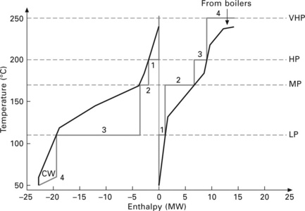
Besides the heat integration of individual processes, it is also possible to obtain heat recovery and power cogeneration targets for entire sites consisting of more than one production process. The procedure is based on thermal profiles of heat sources and heat sinks for the entire site that are called total site profiles (TSPs) (Dhole and Linnhoff, 1993; Klemeš et al., 1997). An example of TSPs together with the total site composite curves is shown in Fig. 16.2.
As sugar plants are mostly not isolated, but interconnected with power plants and in many cases ethanol distilleries, as well as may provide heating for surrounding civic settlements, the total site methodology has been successfully applied. It typically considers a total site comprising sugar beet or cane delivery, storage, pre-processing and processing, packaging and serving the nearby villages or towns. An example of this setup is shown in Fig. 16.3.
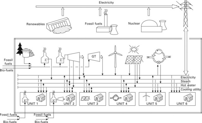
16.3 Locally integrated energy sector (LIES) CHP (after Perry et al., 2008).
Additionally, locally installed boilers, consuming traditional fossil-based fuels, biomass or waste, can also help to meet the process energy requirements, when demand is high or other sources are unavailable. Heating/cooling and power not required by one unit can be fed to a local grid system, and then passed to another unit that is unable to meet its demands locally. The grid system can distribute power (electricity) as well as heating agents such as hot water or steam. In geographic locations where air conditioning is required, a cooling distribution main could also be provided.
16.4 Types of small and micro combined heat and power (CHP) suitable for the food industry
Decentralised power generation combined with heat supply (CHP) is an important technology for improving energy efficiency, security of energy supply and reduction of CO2 emissions. This section provides an overview of advanced energy technologies which can contribute to the more efficient energy supply of food industries via in-house generation.
Many governments encourage micro-CHP system deployment in order to enable meeting international and domestic targets on carbon emissions. Recognising the importance of the issue, the UK government has adopted a policy of incentives to support the development of the technology. As recently as February 2010 (CHPA, 2010) a feed-in tariff of 10 pence per kWh has been adopted in the United Kingdom. This scheme concerns all micro-CHP units with capacity below 2 kW, regardless of whether or not renewables are used. Micro-CHPs are already being developed for applications in SFH (small family houses) and MFH (medium family houses) and SMEs due to their technical and performance features, including high overall efficiency above 90%, low maintenance requirements as well as very low noise levels and low emissions of NOx, COx, SOx and particulates.
An assessment has been done of the performance enhancement when applying micro-CHP in residential applications, which compares the new technologies with a base case employing a condensing boiler of 90% efficiency and network electricity (from the grid), which costs approximately 680 £/y (Peacock and Newborough, 2005). The study showed sizable theoretical savings in both cost and carbon foot print (CFP). The CO2 emissions saving was evaluated as up to 9% for Stirling engines and 16% for fuel cells (FCs), while the energy cost savings reached up to 14.6% for Stirling engines and up to 40% for operating an FC at excess electricity generation and selling it to the grid. It should be pointed out that FCs still need further development to achieve longer service availability and lower investment costs, at sufficient levels to be applied in the food industry. However, the possible savings in fuel and emissions from a separate source (Slowe, 2006) look very promising (Fig. 16.4).
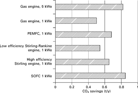
16.4 Annual microCHP CO2 savings compared to grid electricity and boiler alternatives (after Slowe, 2006).
A market analysis and field tests in Germany and the UK (Berger et al., 2006; Forster, 2006; Carbon Trust, 2005) were evaluated focusing on energy producers and conversion techniques with a high development status. These products are either close to market introduction, undergoing EC certification or have already been matured. The following technology types are discussed in relation to possible application in the food industry:
16.4.1 Internal combustion - reciprocating engines
Reciprocating engines are prime movers very extensively used in the food industries. These engines are suitable for smaller food processing sites with relatively lower power-to-heat ratios (PHR). A US market evaluation estimates the share of the food industry as almost 10% of all applications of reciprocating engines on the market for the year 2000 (Energy Solutions Center, 2004).
A typical reciprocating engine (diesel, gas, multiple fuel) and a generator linked to the engine can efficiently produce electricity, over wide power ranges. Gas engines are most suitable for back-up applications. Diesel engines are recommended for continuous base load use. One of their main drawbacks is their relatively noisy operation, which for industrial applications can be compensated using proper noise insulation. The moving parts require regular maintenance, which results in certain costs - up to 0.01-0.015 (US$/y 2000) US$/kWh (Onsite Sycom Energy Corp., 2000) and CFP (Perry et al, 2008). CHP based on reciprocating engines are more applicable to stable energy demands with fewer peaks in the electricity and heat consumption profiles (Alanne and Saari, 2004). The most efficient performance can be achieved by the proper selection of the size of the internal combustion engine, the capacity of thermal and electrical storage systems and the operation scenario on the energy performance of the entire micro-CHP system (onovwiona et al., 2007).
16.4.2 CHP using microturbines
Gas turbines with electrical power generation from 25 to 250 kW, usually referred to as microturbines, can be also used for cogeneration. Such a facility generally consists of a generator, a compressor, a combustion chamber, and a turbine connected by a shaft, with a heat recovery module linked to the turbine exhaust. The high temperature of the turbine exhaust gas (450-550 °C) enables considerable heat cogeneration. Among other advantages, they feature low noise levels, small size and lower emission levels (especially NOx) compared with reciprocating engines (Soares, 2007). Gas and liquid fuels are suitable for microturbines. However, microturbines have low electrical efficiency, especially on part load, while capital and maintenance costs are rather high. Therefore CHPs with microturbines are most applicable for high steam production, with fixed output volume and similar applications.
16.4.3 External combustion - Stirling engines
The Stirling engine is a reciprocating engine with its cylinder closed and combustion taking place outside the cylinder. Stirling engines are characterised by rather low emissions (especially NOx) and lower noise levels. External combustion also requires less maintenance which favourably influences the carbon footprint of the technology. The Stirling engine is usually quiet because the combustion is not explosive and it can use almost any combustible fuel and any source of heat, including biomass. This type of CHP has rather low electrical efficiency, about 25-30% when natural gas is used as a fuel. When solid fuels (e.g., biomass) are used, the efficiency can even be as low as 15%, making them suitable for serving energy demands with low power-to-heat ratios. Their low efficiency supports their use as back-up power supplies rather than for continuous use (Peacock and Newborough, 2005).
16.4.4 Fuel cells (FC)
A FC produces electricity electrochemically, by combining fuel and atmospheric oxygen. Lower-temperature FCs need pure hydrogen (e.g., proton exchange membrane fuel cell (PEMFC), phosphoric acid fuel cell (PAFC) while higher temperature fuel cells (solid oxide fuel cells (SOFC) and molten-carbonate fuel cells (MCFC)) can also process gases containing carbon monoxide. Hydrogen can be obtained from various fuels by means of a reforming process. The electrical efficiency of these systems can be as high as 45-55% (Alanne and Saari, 2004; Varbanov et al., 2006). If pure hydrogen is used, the only direct emission is water. If reforming is used, CO2 and a minimal amount of oxides of sulphur and nitrogen are formed, depending on the fuel. Other benefits are noiselessness, reliability, modularity, and rapid adaptability to load changes. Modularity brings substantial scalability and may substantially reduce the economy of scale effect (Yamamoto, 2000; Varbanov and Klemeš, 2008).
16.5 Established combined heat and power (CHP) technologies for the food industry
This section discusses specific established CHP technologies already having application in the food industry or having the potential to be applied.
16.5.1 Rankine cycle technologies
Siddhartha Bhatt and Rajkumar (2001) and several other authors presented combined heat and power studies relating to cane sugar factories. Part of the fuel energy supplied to the boiler is transferred to steam turbines through high-pressure steam that in turn powers the turbine and generator. This separation of the combustion from the working fluid enables steam turbines to operate with a variety of fuels including natural gas, solid waste, coal, wood, wood waste and agricultural byproducts.
The capacity of commercially available steam turbines typically ranges from 50 kW to over 250 MW. The lower end of this range is suitable for smaller-scale CHP. Although steam turbines are competitively priced compared to other prime movers, the costs of a complete boiler/steam turbine CHP system are relatively high on a per kW basis. This is because steam turbines are typically sized with low power-to-heat ratios, and have high capital costs associated with the fuel and steam handling systems and the custom built nature of most installations.
16.5.2 Gas turbine-based CHP
Gas turbines (GT) for industrial use are generally available in a wide interval of capacities ranging from 500 kW to 250 MW and can operate on a variety of fuels such as natural gas, synthesis gas, landfill gas and fuel oils (US EPA, 2010). In recent years US and European companies have started also offering micro gas turbines (see Section 16.4.2). These include Turbec SpA (TURBEC, 2010), as well as Capstone Turbine Corporation (CAPSTONE, 2010) and Calnetix Power Solutions (CALNETIX, 2010) in the United States. Most gas turbines typically operate on gaseous fuel with liquid fuel as a backup. Gas turbines can be used in a variety of configurations including simple cycle generating only power, CHP - where its exhaust heat is used for generating process steam or direct process heating, and combined cycle operation in which the GT exhaust is used to power steam turbines for generating additional power. The steam cycle placed below the gas turbine in the combined cycle arrangement is often referred to as the ‘bottoming cycle’, while the GT is the ‘topping cycle’. Another variation is to extract process steam at intermediate levels from the combined cycle arrangement. The capabilities of this technology are very broad and flexible, allowing serving food processing sites from different sectors and of different scales. Most GT exhausts allow generating high pressure (HP) steam at 40 bar and higher. By allowing the bottoming Rankine cycle to extract steam at intermediate pressures and to eventually employ condensing steam turbines, a very wide range of demands with different power-to-heat ratios can be served.
Much of the gas turbine-based CHP capacity currently existing in the United States and the European Union consists of large combined-cycle CHP systems that maximise power production for sale to the grid. Simple-cycle CHP applications are common in smaller installations, typically less than 40 MW. The suitability of employing GT-based CHP at food processing sites depends on the demand parameters and the nature of the raw materials used. For instance, for cane-based sugar plants one of the primary objectives is to maximise the utilisation of the bagasse. In such case the preferred method in Brazil is by simple Rankine cycle-based CHP. However, it is possible to utilise the bagasse in a GT-based system, first deriving synthesis gas via gasification. While examples of established use of bagasse gasification in sugar industries are difficult to find, theoretical works and small-scale experiments are already under development (Pellegrini and de Oliveira Jr, 2007; Rodrigues et al., 2003)
16.5.3 Reciprocating engines
Reciprocating engines, discussed previously, are also used for energy applications in the food industry. An EU-FP6 project report (POLY SMART, 2009) describes the use of a diesel engine in a trigeneration application, using the lower-temperature recovered heat in an absorption chiller and the higher-grade heat is used for generating process steam.
Spark ignition (SI) engines use spark plugs with a high-intensity spark of timed duration to ignite a compressed fuel-air mixture within the cylinder. They are available in sizes up to 5 MW, running mostly on natural gas, but propane, gasoline and landfill gas can also be used. Diesel engines (compression ignition, or CI engines), are very efficient power generation options. They operate on diesel fuel, heavy oil, or recently biodiesel has become an option. Dual fuel engines, using predominantly natural gas with a small amount of diesel pilot fuel, are also installed. Higher-speed diesel engines (1200 rpm) are available in capacities up to 4 MW, while lower-speed diesel engines (60-275 rpm) can be larger - up to 65 MW. Reciprocating engines start quickly, follow load well, have good part-load efficiencies and are generally highly reliable. The overall energy generation availability can be enhanced by deploying multiple reciprocating engines. Reciprocating engines are well suited for applications that require hot water or low-pressure steam.
16.6 High-efficiency technologies in theoretical and demonstration stages
As discussed in Section 16.2, certain food industry sectors, e.g. meat processing, have energy demands with high PHR. In order to use the fuels efficiently, there are two principal ways of satisfying the demands of such sites: to use CHP technologies with high overall efficiency but lower PHR, utilising somehow the extra heat generated, or to employ technologies with high PHR and high electrical efficiency. This section addresses situations in the food industry where higher electrical efficiencies are required for processes.
Fuel cell (FC) systems are one of the most promising emerging technologies for power generation, which have the potential to replace conventional methods by offering higher energy conversion efficiencies and significantly lower greenhouse gas emissions (Varbanov and Friedler, 2008). They have not yet been widely commercialised due to high capital costs and the need to improve their reliability and lifespan. The achievable electrical efficiency for FCs ranges from 40% up to 60% and above. There are several classes of FCs with small variations for each type. The most researched types include proton-exchange FC (PEFC), phosphoric acid FC (PAFC), molten-carbonate FC (MCFC), and solid-oxide FC (SOFC).
There are many factors influencing the FC efficiency, of which the operating temperature is the most important. Based on an analysis by Yamamoto, (2000), it can be seen that the correlation between the efficiency and the operating temperature is very pronounced, differing by more than 20% between the PEFC and SOFC (Fig. 16.5).
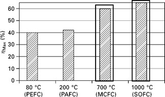
16.5 Variation of FC efficiency with operating temperature (after Yamamoto, 2000).
Another important feature is that the exhausts of hotter FCs are available at temperatures above 500 °C, making them suitable for integration with bottoming cycles and cogeneration. Higher temperatures favour higher potential for further power generation or cogeneration from the FC exhausts. Any drop in the temperature drastically decreases this potential.
The principle and main parameters of a MCFC are discussed next as an example FC technology.
16.6.1 Molten-carbonate fuel cells (MCFC)
The MCFC is one of the fuel cell types operating at high temperatures (550-700°C). It is considered suitable mainly for stationary power generation. In an MCFC, natural gas or a gaseous low molecular weight hydrocarbon-containing fuel is fed to the anode. To the cathode, a mixture of oxygen (from the air) and carbon dioxide (from the anode) is introduced. This is a continuous process. The electrolyte is a mixture of molten alkali metal carbonates, usually a binary mixture of potassium and lithium, or lithium and sodium carbonates. The molten carbonates are kept in a ceramic matrix of LiAlO2 (Larminie and Dicks, 2000). At operating temperatures of 550-700°C, the carbonates are highly conductive to carbonate ions (CO32 −) providing ionic conduction. The moving ions inside the electrolyte, along with the electrons in the outer circuit, complete the electric circuit for power production. The high operating temperature of the MCFC gives an opportunity for greater fuel flexibility, use of less expensive electro-catalysts and high overall system operating efficiencies.
The basic configuration of a MCFC system consists of a fuel cell stack, an internal reforming chamber, a catalytic combustor and inlet/outlet pipes for the various process streams. The process flow diagram of the system is shown in Fig. 16.6, Natural gas and water from the supply system enter the fuel cell reformer where they get reformed internally (indirect reforming) by the heat content of the exothermic fuel cell reaction. The endothermic reforming reaction taking place in the fuel reformer produces carbon monoxide (CO) and hydrogen (H2). The anode exhaust is sent to a catalytic combustor where the unused fuel is burned in the presence of air taken from the ambient for going through the cathode. The amount of air provided must be more than the stoichiometric air requirement for the fuel combustion. The flue gases are then introduced in the cathode after cooling them to a suitable temperature. Otherwise, at high temperatures, electrolyte evaporation and material corrosion would occur. Carbon dioxide, oxygen and electrons, returning from the external electric circuit, react together in the cathode to produce carbonate ions (CO32 −). These migrate from the cathode to the anode via the electrolyte matrix, where they react with the hydrogen from the anode stream to produce water, carbon dioxide and electrons. The electrons pass from the fuel electrode (anode) to the oxidant electrode (cathode) via the electric circuit, external to the electrolyte matrix. The reactions occurring at the anode and the cathode oxidise the hydrogen and reduce CO2 to carbonate ions. In addition, a water gas shift reaction also occurs at the anode resulting in additional production of hydrogen.
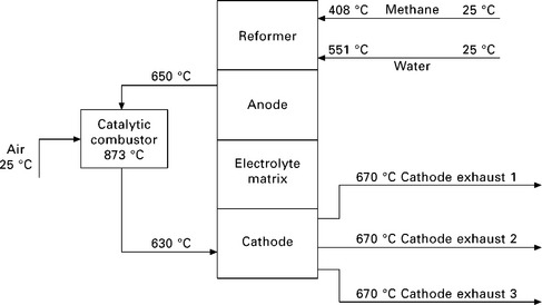
16.6 Simple MCFC process flow diagram (after Varbanov et al., 2006).
An example MCFC of the described type has been analysed (Varbanov et al., 2006), generating 2.32 MW of electricity. It needed 0.1 kg/s of methane, equivalent to 5.002 MW energy input, resulting in 46.38% electrical efficiency.
16.6.2 Fuel cell combined cycles (FCCC) using MCFC and solid oxide fuel cells (SOFC)
MCFCs feature an important thermodynamic limitation. Operation at temperatures higher than 700 °C leads to falling gains in the fuel cell performance. This happens because of increased electrolyte loss from evaporation and corrosion of materials at high temperatures. Similarly, SOFCs also have certain limitations on their operating temperature and efficiency, mainly in terms of suitable materials and their durability. Therefore, any further increases in fuel utilisation efficiency should be sought in a different direction. One especially interesting option is to consider the formation of a fuel cell combined cycle (FCCC) for power generation, which can be eventually employed for stand-alone power generation, as well as for cogeneration. The main reason for considering this option is the significant amounts of high-grade waste heat released by MCFC and SOFC systems. The literature sources on combining fuel cells with gas and steam turbines clearly illustrate the potential to achieve high power and cogeneration efficiencies as well as economic viability (Massardo and Bosio, 2002; Karvountzi et al., 2004; Kurz, 2005; Varbanov et al, 2006).
The potential to use the high-temperature exhaust for process heat cogeneration from SOFC or MCFC can be evaluated in two steps following the hierarchy common for process design:
1. Appropriate heat integration within the FC. This would maximise its fuel efficiency without altering the design and give an estimate of the further heat flows available for steam generation.
2. Steam generation and utilisation in a steam network for process heating or more power generation.
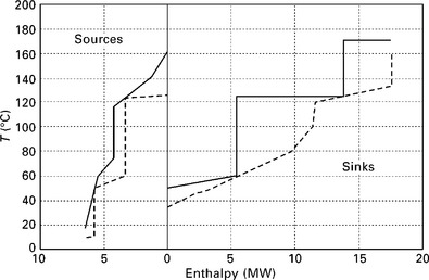
Analysing the MCFC system shown in Fig. 16.6 reveals significant potential for cogeneration. Using pinch analysis (Linnhoff et al., 1982; Klemeš et al., 2010), it is shown that the MCFC heating and cooling demands define a threshold problem with net utility demands only for cooling (Fig. 16.7).
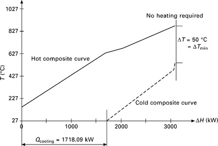
16.7 Composite curves for the MCFC from Fig. 16.4 (∆Tmin = 50 °C).
A similar and more thorough analysis of a SOFC (Varbanov and Klemeš, 2008) has also been performed. The SOFC flowsheet is shown in Fig. 16.8. The pinch analysis of the SOFC system produced the composite curves shown in Fig. 16.9.
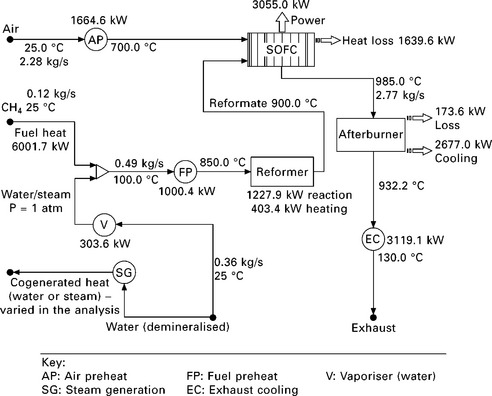
16.8 SOFC flowsheet (after Varbanov and Klemeš, 2008).
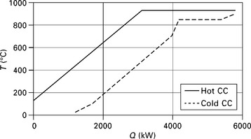
16.9 Composite curves for the SOFC integration (after Varbanov and Klemeš, 2008).
A more complete analysis of the heat-integrated SOFC, combined with generation of hot water or steam, showed remarkable CHP efficiency of over 70% (Fig. 16.10). This value could be eventually increased further if the SOFC design is optimised and the high temperature exhausts could be cooled to lower temperatures than 130 °C.
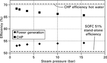
16.10 Overall efficiencies of the combined SOFC and steam system arrangement (after Varbanov and Klemeš, 2008).
16.7 Integration of renewables and waste with food industry energy demands
The comparatively low temperatures make food processing very attractive for utilising various renewables, including ground heat via heat pumps as well as solar thermal energy. There are a number of waste and renewable energy sources which are available to provide local heating and cooling, and in doing so can reduce the costs and the greenhouse gas emissions of industrial sites. The focus of this section is on those sources suitable for application to the food industry. The technologies and sources considered include heat pumps, biomass and solar energy.
16.7.1 Heat pumps
Heat pumps are used to upgrade low temperature heat from sources such as ambient air, exhaust air, ground soil, ground rock, groundwater and surface water, to higher temperature heat outputs which can be used for space or process heating. In the food and beverages industry heat pumps are widely used for cooling and refrigeration, mainly utilising their heat sink side. The two principal technologies used in heat pumps are compression and absorption (Laue, 2006). A compression heat pump consists of an evaporator, compressor, condenser and an expansion valve. They are driven mainly by electricity, but can also be powered by direct drive prime movers - gas or diesel engines, gas or steam turbines. Each heat pump is characterised by its coefficient of performance (COP), which depends on the input temperature of the heat source, and the output temperature required. Under the most usual conditions the COP varies between 4 and 5 for temperature lift about 20-30 °C, but may slip below 4 for higher temperature lift values.
In the food and drink industry, besides for refrigeration as mentioned, heat pumps can also be applied for process heating. An ideal match would be between a low-temperature heat source or cooling demand below the pinch and a moderate-temperature heating demand above the pinch. However, low-grade geothermal energy can also be used.
16.7.2 Biomass
Biomass is another renewable energy source that can provide heat and can reduce the production of greenhouse gases. In many cases it can be readily stored and used when needed. In other cases biomass is a side product or waste from the main production processes, e.g. bagasse and molasses in sugar processing.
Depending on the form in which biomass is available, different methods can be applied for utilising it. First, and by far the most common, is direct firing of biomass when it is available in a sufficiently dry condition. However, if higher moisture and/or potentially dangerous components are present, it may be preferable to apply anaerobic digestion of the biomass material, obtaining biogas, which can be further utilised in gas-fired boilers, gas turbine variants (including microturbines) as well as in fuel cells.
The biomass renewable energy source can also be used in gasification processes for the production of heat and power. A gasification system thermally converts biomass to synthesis gas, which can then be used to produce fuels, products, power and hydrogen (US DOE, 2008). Currently most large-scale gasification systems research is pursued, but smaller modular gasification systems are also planned. These systems would operate in the range of 5 kW to 5 MW (CIWM, 2008), and would provide heat and power from localised sources of biomass. The gasification product, composed primarily of carbon monoxide and hydrogen, is cleaned and then used in gas turbines or internal combustion engines. In addition to the power produced, waste heat can be directed to district heating based systems.
16.7.3 Using solar energy
Solar energy is another renewable source that can be used for both heating and cooling. Solar heating is a mature technology that has proven to be reliable and cost-competitive since solar water heaters were introduced over 30 years ago. Although these systems have been centred mainly on producing heat and power for individual or large residential/commercial buildings, there has also been widespread interest in using concentrated solar heat systems for industrial applications (Rantil, 2006).
In active solar heating systems, water, or another heat transfer fluid, is circulated through a duct and heated by transfer from direct solar radiation on the collector panel. Various designs of collectors are utilised in order to concentrate the solar radiation on the fluid duct and to maximise solar gains. The amount of heat energy captured per square metre of collector surface area varies with design and location but typically can range from 300 to 800 kWh/(m2y). Some designs use a heat transfer fluid that, when warmed, flows to a storage tank or a heat pump where the heat is further upgraded and used by consumers.
An interesting study illustrating the integration of solar captured heat is presented by Atkins et al. (2010). The described example presents a New Zealand dairy milk powder plant located in the central North Island. The case study has been conducted to explore the possible retrofit with the integration of an industrial solar thermal system to the milk powder plant. A 1000 m2 evacuated tube solar collector field is assumed. Evacuated tubes have been considered the most appropriate collector design in this case to fit the required temperature levels and flow rates. However, the overall findings can be generalised to other collector types as well. The plant operates from the beginning of August through to the end of April, when there is a three month shut down due to low milk production in the winter months. This period of no production also coincides with the lowest ambient temperatures and solar radiation levels.
The plant data have been analysed using pinch analysis using minimum temperature difference ∆Tmin = 5 °C. The hot and cold utility targets obtained are 1674 and 2927 kW, respectively, with the pinch located at 45 °C for the hot streams and 40 °C for the cold streams. They consider several options for placing the captured solar heat, where the main challenges are how to ensure appropriate placement of the solar heat utility above the pinch and at the same time to maximise the solar collector efficiency. The most beneficial scenarios found were: (i) solar heat integration at constant capture flow and varying temperature resulting in reduction of the hot utility by 14% and of the cold utility by 4%; and (ii) solar integration alone - above the pinch at constant capture flow resulting in 7% hot utility reduction.
16.8 Potential applications
There is an enormous potential to apply small-scale CHP in the food industry. In this section two case studies are presented. First, an application of a high-temperature fuel cell to powering a Japanese brewery is presented to outline the practical potential of this new technology. Second, a novel idea for integrating smaller-scale industrial plants and other energy consumers/providers is covered to underscore the importance of taking advantage of local context and potential energy partnerships for successfully implementing distributed generation.
16.8.1 MCFC applied to a Japanese brewery
A Brewery in Japan owned by Kirin Beer operates a 250 kWe molten carbonate fuel cell developed by US-based FuelCell Energy together with Marubeni Corporation in Tokyo. It is reported as the world’s first fuel cell to run on digester gas from a waste treatment plant (Kirin Brewery, 2003). The MCFC has been supplying roughly 4% of the electric power and about 1% of the steam for the brewery Toride Plant in Tochigi Prefecture since early April 2003.
Marubeni has been responsible for the entire package of investment and for installation, maintenance and operational management of the fuel cell, with the support of the New Energy & Industrial Technology Development Organization (NEDO). The fuel used consists of digester gas (mainly methane) generated by anaerobic treatment at the brewery’s waste treatment plant. All the power generated by the fuel cell and the steam generated from waste heat recovery is supplied for process heating to the brewing plant. Using the fuel cell in cogeneration mode gives a dramatic improvement in overall efficiency to 72% or better (i.e. power generating efficiency of > 47% and waste heat recovery efficiency of over 25%).
16.8.2 Locally integrated energy sectors
Total site targeting has provided a method for analysing the heat sources and sinks from more than one process, as discussed in Section 16.3.2 (Klemeš et al., 1997). This methodology can be adopted for the analysis of heating and cooling requirements in an enlarged geographical area, which is referred to as a locally integrated energy sector (LIES) (Perry et al., 2008). The LIES concept can be very useful for application to the food industry, especially taking into account the relatively smaller scale of many food production plants in Europe.
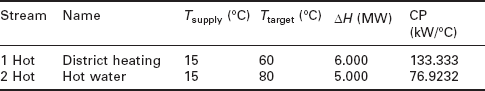
The following example illustrates the concept. Consider two small-scale industrial processing plants, coupled with a hospital complex and a group of residential dwellings and office complexes. The process streams of the industrial processes are shown in Tables 16.1 and 16.2. The grand composite curves, built for ∆Tmin = 20 °C from the data for plants A and B, are shown in Figs 16.11 and 16.12.
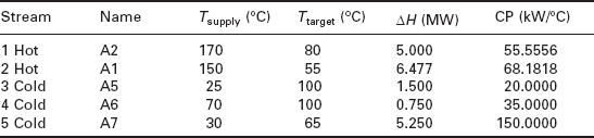
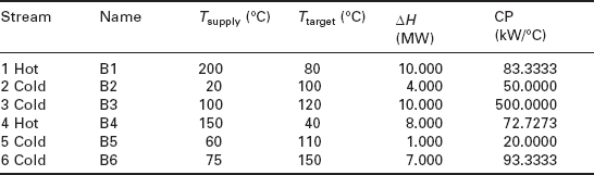
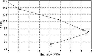
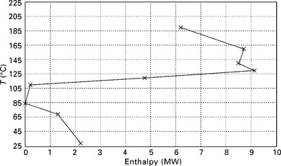
Plant A has no net heating requirements, indicated by the lack of above- the-pinch area, but has a large net cooling requirement below the pinch - excess heat that has to be removed. Consequently there is approximately 4 MW of heat which is available at temperatures of around 120 °C. This heat is available at a temperature sufficient for the production of steam. Plant B requires an external heating source above the pinch, again at a temperature of around 120 °C, and also has a small amount of excess heat which has to be removed by cooling below the pinch. This excess heat, of approximately 1.5 MW, could be used to produce hot water at temperatures of around 70 °C - sufficient to use in the residential and office areas of the LIES, provided the transportation distances are not too long.
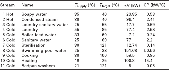
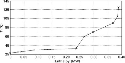
The LIES under consideration also includes a hospital complex - Plant C (Herrera et al., 2003). The process stream data for this unit is shown in Table 16.3 and the process grand composite curve with a ∆Tmin = 20 °C, derived from this original data, is shown in Fig. 16.13. In this particular unit, there is a heat sink of around 400 kW above the pinch which requires supply of external heating.
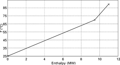
The final unit in the energy sector is composed of a group of residential dwellings and office complexes (Plant D). The heating requirements in this mixed unit are aggregated hot water requirements and space heating. The process stream data are given in Table 16.4 and the process grand composite curve, again at ∆Tmin = 20 °C, in Fig. 16.14.
The total site profiles diagram of the LIES is given in Fig. 16.15. The heat sources and heat sinks of the involved processes have been combined to produce the overall total site sink profile and total site source profile. Without integration, the LIES would need to dispose of 6.2 MW of heat, and 17.5 MW of heat would have to be supplied from external heating sources (e.g. fossil fuels).
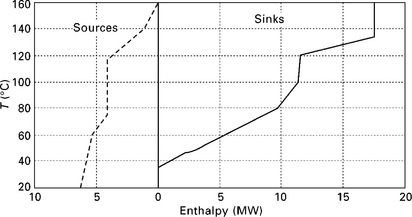
A possible scenario (Scenario 1) for integration in the LIES is shown in Fig. 16.16. In this scenario, a hot water main at a temperature of 60 °C to 40 °C is provided for extracting heat from the total site source profile and supplying heat to the total site sink profile. The amount of generated heat for the hot water supply is 5.5 MW, and the amount of heat that has to be supplied by the hot water is also 5.5 MW. The remaining heat required by the LIES is 12.0 MW, giving a heat reduction of 5.5 MW due to heat integration in the LIES. The external heat required could be provided by a boiler using a carbon neutral fuel such as biomass or waste combustion unit. In this particular case the heat for the hot water system is supplied by the small-scale food processing plants, and the recipients of the heat are the hospital and residential and office complexes. If this heat (the 5.5 MW) was no longer available, then it would need to be supplied from another source.
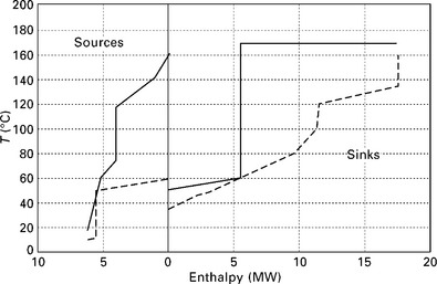
A second scenario, Scenario 2, is shown in Fig. 16.17. In this case a steam main at 125 °C has been added to the system. The heat source from the LIES has now been split between steam (3.1 MW) and hot water (2.4 MW). on the sink side, 8.4 MW of steam is supplied to the hospital and residential and office complexes, and 5.5 MW of hot water. The amount of heat to be supplied by the boiler or waste combustion system remains at 12.0 MW. Economics is a significant factor in the final design potential. Installing both a hot water main and a steam main over the geographical area of the LIES may be an economical option. This needs to be further evaluated in relation to changing energy/capital cost ratios. The recent developments in coping with fluctuating sources (typical for most renewables) and demands have been presented by Varbanov and Klemeš (2010).
16.9 Future trends
A number of possible future configurations for smaller-scale CHP technologies and their users are possible and have good probability for development in the future. Here several possible future directions of development are outlined from the viewpoint of their potential for improving the security of energy supply as well as the overall performance of the industrial processes and the local energy sectors.
16.9.1 Technology development trends
Regarding technology development, the current state of the art for micro- CHP is the Stirling engine, which is very useful and provides security and availability due to its maturity. However, due to its lower power-to-heat ratio (about 0.5) it is not very suitable for industrial applications, which necessitates further developments and a paradigm shift. Particularly fuel cell technology should be more aggressively pursued. It may have significant positive implications on the CHP market as long as sufficient durability, availability and maintainability of the fuel cells can be ensured. Switching to different technologies will also lead to a different power-to-heat ratio, which is quite high (about 1 to 2 for fuel cells). An overview has been presented by Kuhn et al. (2008).
16.9.2 Strategic issues
recently, attention has shifted towards security of supply (van Soest et al., 2006). It has become clear that having energy resources brings influence, and many countries are not hesitating to use that influence when they have it. The energy exporting countries on the one hand realise that because of the ever growing energy demand world-wide, the energy markets are sellers markets these days. They are in a position to sell to the highest bidder and to those users who are willing to accept long-term contracts. The energy importing countries realise that energy is key for economic development, and that short-term scarcities may hamper economic growth for longer periods.
Decentralisation
This is becoming more and more popular as an idea, especially with the development of new energy conversion technologies making available high efficiency at lower and lower costs. An example of such a technology with a great potential is fuel cells. The generation of the heat and power at the premises of the consumer or close nearby has two fundamental advantages: minimisation of energy transportation losses and minimisation of infrastructure failures or disturbances.
The further integration of renewables and maximum waste utilisation
This is another matter of strategic importance. It is closely related to the issues of energy security, environmental protection and sustainable development. In particular, maximising waste utilisation according to an appropriately formulated waste management hierarchy has the potential to provide a win-win development by simultaneously reducing waste disposal and the consumption of external energy resources. A good example of waste utilisation has been provided in Section 16.8.1.
Locally integrated energy sectors
The locally integrated energy sectors discussed in this chapter provide another opportunity - to extend process energy efficiency, waste management and renewables integration to the scope of local communities and towns, thus enabling more efficient utilisation of company resources and symbiosis with other companies and residential areas.
16.10 Sources of further information and advice
The material provided in this chapter highlights the major CHP technologies with an emphasis on smaller-scale ones. However, it is by no means exhaustive. Therefore, this section supplies additional references to provide guidelines for more detailed and comprehensive studies.
16.10.1 Institutional resources
A large number of institutional resources are available over the world. The ones found most useful by the authors are listed next.
The US EPA has compiled a ‘Catalogue of CHP Technologies’ available over the Internet (US EPA, 2010). It contains a number of sections starting with an introductory overview of CHP technologies and accompanied with more detailed analyses of each technology in terms of main characteristics and the potential for their application, also including various CHP efficiency definitions used in industry, research and various standards and regulations.
Another useful US information resource is the ‘California Distributed Energy Resources Guide’ (CDERG, 2010). This is a public benefit website providing information regarding technologies for distributed energy generation, to which the small- and micro-CHP technologies inherently belong. The website contains various sections - e.g. ones dedicated to background and overview, equipment analysis (including prominent suppliers), information on ongoing research, an extensive library of real-life case studies, costing, policy incentives, market analysis, and others.
From the European resources, the Irish Combined Heat and Power Association has compiled a set of resources on CHP technologies including overviews and examples of installed running plants (ICHPA, 2010). The UK Carbon Trust (Carbon Trust, 2010a) also offers an extensive website dedicated to CHP technologies with a special section on micro-CHP (Carbon Trust, 2010b). The section offers an extensive report and guide in PDF format for companies and organisations on the issues of understanding and choosing the right combination of micro-CHP technologies. The guide puts a special emphasis on CO2 emissions minimisation. The Carbon Trust website does require free-of-charge user registration before allowing downloads.
16.10.2 Books
An interesting textbook on microturbines is provided by Soares (2007). It describes the various microturbine types, their applications, and their requirements for installation, maintenance and repair. It also discusses the combination of microturbines with fuel cells for forming combined cycles as well as other integration options.
Knowles et al. (2004) present another useful resource. The book provides an in-context overview of small-scale energy technologies in terms of renewable energy utilisation, technology options such as wind turbines, hydro, micro- CHP (Stirling engines, microturbines, fuel cells and their hybrids), biomass gasification, and electricity distribution issues.
Pehnt et al. (2005) describe CHP and micro cogeneration from a different perspective, emphasising societal and social issues, emissions reduction, economic viability and market analysis.
16.10.3 Journals
There are a variety of peer-reviewed journals available. Those regularly publishing on CHP and micro-CHP issues include:
• Applied Thermal Engineering <www.elsevier.com/wps/find/journaldescription.cws_home/630/description#description>
• Energy - the International Journal <www.elsevier.com/wps/find/journaldescription.cws_home/483/description#description>
• Chemical Engineering Transactions <www.aidic.it/CET>
• Renewable and Sustainable Energy Reviews <www.elsevier.com/wps/find/journaldescription.cws_home/600126/description#description>
• Clean Technologies and Environmental Policy <www.springer.com/environment/sustainable+development/journal/10098>
• Journal of Cleaner Production <www.elsevier.com/wps/find/journaldescription.cws_home/30440/description#description>
• Journal of Clean Technologies and Environmental Policy <www.springer.com/environment/sustainableTdevelopment/journal/10098>
• Resources, Conservation and Recycling <www.elsevier.com/wps/find/journaldescription.cws_home/503358/description#description>
16.10.1 Conferences
There are also a number of conference options to choose from that cover CHP in the food industry and also smaller-scale cogeneration. However, these issues are not always completely coherently covered by a specific conference. A small selection of high-profile conferences is provided next.
The Total Food series of biennial, international conferences was initiated in 2004 by the Royal Society of Chemistry Food Group and the Institute of Food Research, Norwich. The aim of Total Food is to debate global research and development relevant to exploiting the whole food crop rather than the limited proportion that is consumed at present. The conference considers the topics of energy supply and efficiency in food processing.
The series of conferences Process Integration, Modelling and Optimisation for Energy Saving and Pollution Reduction (PRES), organised annually since 1999, <www.conferencepres.com>, provides a forum for exchanging information and views on energy technologies and emissions minimisation from a wide spectrum of industries, including increasing participation of food processing engineers and researchers.
The other prominent forums include:
• European Symposium on Computer Aided Process Engineering (ESCAPE), organised annually since 1992, <www.cape-wp.eu>
• AIChE International Congress on Sustainability Science and Engineering (ICOSSE) organised since 2009, <www.aiche.org/IFS/Conferences/index.aspx>
• Dubrovnik Conference on Sustainable Development of Energy, Water and Environment Systems (SDEWES), organised biennially since 2002, <www.sdewes.fsb.hr>
16.11 References
Alanne, K., Saari, A. Sustainable small-scale CHP technologies for buildings: the basis for multi-perspective decision-making. Renewable and Sustainable Energy Reviews. 2004; 8(5):401–431.
Atkins, M., Walmsley, M.R.W., Morrison, A.S. Integration of solar thermal for improved energy efficiency in low-temperature-pinch industrial processes. Energy. 2010; 35(5):1867–1873.
Berger, S., Raabe, E., Zernahle, O. Market analysis for microCHP - application of microCHP in the power range between 1 and 5 kWel. Germany: Report, Berliner Energieagentur GmbH; 2006.
CADDET. Center for the Analysis and Dissemination of Demonstrated Energy Technologies. Integrated Heat Recovery in a Malt Whisky Distillery. 1994. [Project No. UK-94–509].
CALNETIX. Calnetix Power Solutions. [Online]. www.tapower.com, 2010. [accessed 08/06/2010].
CAPSTONE. Capstone Turbine Corporation [Online]. www.capstoneturbine.com, 2010. [accessed 08/06/2010].
Carbon Trust. The Carbon Trust’s Small-Scale CHP field trial update 2005; [CTC513].
Carbon Trust. Combined Heat and Power. [Online]. www.carbontrust.co.uk/emerging-technologies/technology-directory/pages/combined-heat-power.aspx, 2010. [accessed 10/06/2010].
Carbon Trust. Micro Combined Heat and Power Accelerator. [Online]. www.carbontrust.co.uk/emerging-technologies/current-focus-areas/pages/micro-combined-heat-power.aspx, 2010. [accessed 10/06/2010].
CDERG. California Distributed Energy Resources Guide. [Online]. www.energy.ca.gov/distgen/index.html, 2010. [accessed 09/06/2010].
CHPA. Government cash reward for microCHP. A Combined Heat and Power Association press release, 5 February 2010. [Online]. www.chpa.co.uk/news/press_releases/2010/01.02.10%20Government%20cash%20reward%20for%20microCHP.pdf, 2010. [accessed 07/06/2010].
CIWM. Energy from Waste: A Good Practice Guide, The Chartered Institution of Waste. Northampton: Management; 2008.
DEFRA. Food Industry Sustainability Strategy. [Online]. www.defra.gov.uk/foodfarm/policy/foodindustry/documents/fiss2006.pdf, 2006. [accessed 28/07/2010].
Dhole, V.R., Linnhoff, B. Total site targets for fuel, co-generation, emissions, and cooling. Computers & Chemical Engineering. 1993; 17:S101–S109.
Elkin, D., Stevens, C. Environmental and consumer issues regarding water and energy management in food processing. In: Klemeš J., Smith R., Kim J.-K., eds. Handbook of Water and Energy Management in Food Processing. Cambridge: Woodhead Publishing Limited; 2008:29–44.
Energy Solutions Center. Reciprocating Engines [Online]. www.energysolutionscenter.org/distgen/AppGuide/Chapters/Chap4/4-1_Recip_Engines.htm, 2004. [accessed 29/07/2010].
Forster, H. Ideal solutions with warm-up. Energiespektrum. 2006; 11:28–30.
Genne, I., Derden, A. Water and energy management in the slaughterhouse. In: Klemeš J., Smith R., Kim J.-K., eds. Handbook of Water and Energy Management in Food Processing. Cambridge: Woodhead Publishing Limited; 2008:805–815.
Herrera, A., Islas, J., Arriola, A. Pinch technology application in a hospital. Applied Thermal Engineering. 2003; 23:127–139.
ICHPA. Welcome to the Irish Combined Heat and Power Association. [Online]. www.ichpa.com/index.php, 2010. [accessed 09/06/2010].
Karvountzi, G.C., Price, C.M., Duby, P.F. Comparison of molten carbonate and solid oxide fuel cells for integration in a hybrid system for cogeneration or tri-generation. ASME, Advanced Energy Systems Division (Publication) AES. 2004; 44:139–150.
Kemp, I.C., Pinch Analysis and Process Integration a second edition of, (1982, last edition 1994)linnhoff B., Townsend D.W., Boland D., Hewitt G.F., Thomas B.E.A., Guy A.R., Marsland R.H., eds. User Guide on Process Integration for the Efficient Use of Energy, IChemE, Rugby. Butterworth-Heinemann/IChemE Series.. 2007.
Brewery, Kirin. Japanese brewery MCFC powered by digester gas. Fuel Cells Bulletin. 2003; 2003(7):4.
Klemeš, J., Dhole, V.R., Raissi, K., Perry, S.J., Puigjaner, L. Targeting and design methodology for reduction of fuel, power and CO2 on total sites. Applied Thermal Engineering. 1997; 17(8/10):993–1003.
Klemeš, J., Kimenov, G., Nenov, N. Application of pinch-technology in food industry. CHISA’98/1st Conference PRES’98, Prague, Lecture F6.6. 1998; 136.
Klemeš, J., Friedler, F., Bulatov, I., Varbanov, P. Sustainability in the Process Industry: Integration and Optimization. New York: McGraw-Hill Professional; 2010.
Knowles, M., Burdon, I., Beith, B. Micro Energy Systems: Review of Technology, Issues of Scale and Integration. New York: John Wiley and Sons; 2004.
Kuhn, V., Klemeš, J., Bulatov, I. MicroCHP: overview of selected technologies, products and field test results. Applied Thermal Engineering. 2008; 28(16):2039–2048.
Kurz, R. Parameter optimization on combined gas turbine-fuel cell power plants. ASME Journal of Fuel Cell Science and Technology. 2005; 2:268–273.
Larminie, J., Dicks, A. Fuel Cell Systems Explained. Chichester: Wiley; 2000.
Laue, H.J.Clauser C., Strobl T., Zunic F., eds. Heat pumps. In: Renewable Energy Vol 3C. Berlin: Springer, 2006.
Linnhoff, B., Hindmarsh, E. The pinch design method for heat exchanger networks. Chemical Engineering Science. 1983; 38(5):745–763.
1982. (last edition, Linnhoff, B., Townsend, D.W., Boland, D., Hewitt, G.F., Thomas, B.E.A., Guy, A.R., Marsland, R.H. User Guide on Process Integration for the Efficient Use of Energy. Rugby: IChemE; 1994.
Massardo, A.L., Bosio, B. Assessment of molten carbonate fuel cell models and integration with gas and steam cycles. Journal of Engineering for Gas Turbines and Power. 2002; 124:103–109.
Onovwiona, H.I., Ugursal, V.I., Fung, A.S. Modeling of internal combustion engine based cogeneration systems for residential applications. Applied Thermal Engineering. 2007; 27:848–861.
Onsite Sycom Energy Corp. The market and potential for combined heat and power in the commercial/institutional sector. US Department of Energy, Energy Information Administration; 2000.
Peacock, A., Newborough, M. Impact of microCHP systems on domestic sector CO2 emissions. Applied Thermal Engineering. 2005; 25:2653–2676.
Pehnt, M., Cames, M., Fischer, C., Praetorius, B., Schneider, L., Schumacher, K., VoB, J.-P. Micro Cogeneration: Towards Decentralized Energy Systems. Berlin: Springer; 2005.
Pellegrini, L.F., de Oliveira, S., Jr. Exergy analysis of sugarcane bagasse gasification. Energy. 2007; 32(4):314–327.
Perry, S., Klemeš, J., Bulatov, I. Integrating waste and renewable energy to reduce the carbon footprint of locally integrated energy sectors. Energy. 2008; 33(10):1489–1497.
POLYSMART. Meat processing factory in Baza POLYSMART Milestone 6.8, [Online]. www.polygeneration.org/cms/upload/concepts/trigeneration/CS_1.4.3.pdf, 2009. [accessed 13/04/2010].
Rantil, M. Concentrating solar heat - kilowatts or Megawatts? Seminar. Renewable heating and cooling - from RD&D to deployment’, International Energy Agency, April 2006, [Online]. www.iea.org/Textbase/work/workshopdetail.asp?WS_ID=243, 2006. [accessed 17/05/2010].
Rodrigues, M., Walter, A., Faaij, A. Co-firing of natural gas and biomass gas in biomass integrated gasification/combined cycle systems. Energy. 2003; 28(11):1115–1131.
Siddhartha Bhatt, M., Rajkumar, N. Mapping of combined heat and power systems in cane sugar industry. Applied Thermal Engineering. 2001; 21:1707–1719.
Slowe, J. MicroCHP to increase energy efficiency: emerging technologies, products and markets, Delta Energy & Environment Affiliation, [Online]. mail.mtprog.com/CD_Layout/Day_2_22.06.06/1400-1545/ID33_Slowe_final.pdf, 2006. [accessed 17/05/2010].
Soares, C. Microturbines Applications for Distributed Energy Systems. Maryland Heights, MO: Elsevier Inc.; 2007.
TURBEC. Turbec SpA Corporate web site. [Online]. www.turbec.com/company/distributors.asp, 2010. [accessed 08/06/2010].
Urbaniec, K., Klemeš, J. Water and Energy Management in the Sugar Industry. In: Klemeš J., Smith R., Kim J.-K., eds. Handbook of Water and Energy Management in Food Processing. Cambridge: Woodhead Publishing Limited; 2008:863–884.
US DOE. US Department of Energy, 2008, Energy Efficiency and Renewable Energy, [Online]. www1.eere.energy.gov/biomass/fy04/fundamental_biomass_gas.pdf, 2008. [accessed 17/07/2008].
US EPA. Catalog of CHP Technologies. [Online]. www.epa.gov/chp/basic/catalog.html, 2010. [accessed 08/06/2010].
van Soest, J.P., Bartholomeus, P., Overdiep, H., Klimbie, B. From microopportunities to macro-changes. Micro CHP in Perspective. [Online]. www.jpvs.nl/downloads/micro.chp in perspective.pdf, 2006. [accessed 10/06/2010].
Varbanov, P., Friedler, F. P-graph methodology for cost-effective reduction of carbon emissions involving fuel cell combined cycles. Applied Thermal Engineering. 2008; 28(16):2020–2029.
Varbanov, P., Klemeš, J. Analysis and integration of fuel cell combined cycles for development of low-carbon energy technologies. Energy. 2008; 33(10):1508–1517.
Varbanov, P., Klemeš, J. Total sites integrating renewables with extended heat transfer and recovery. Heat Transfer Engineering. 2010; 31(9):733–741.
Varbanov, P., Klemeš, J., Shah, R.K., Shihn, H. Power cycle integration and efficiency increase of molten carbonate fuel cell systems. Journal of Fuel Cell Science and Technology. 2006; 3(4):375–383.
Yamamoto, O. Solid oxide fuel cells: fundamental aspects and prospects. Electrochimica Acta. 2000; 45:2423–2435.