6.11. Placement of Unconventional Gas in the Energy Picture
6.11.1. Reserve Growth Potential of Unconventional Gas
“…the modeling approach used by the USGS (U.S. Geological Survey) to characterize this phenomenon is statistical rather than geologic in nature.”
6.11.2. Reservoir Categories in the United States
Table 6.24
Depositional Environments and Rock Units Selected for Study of Reserve Growth, and Geologic Age and General Location of Units
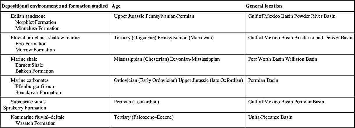
6.11.2.1. Eolian Reservoirs
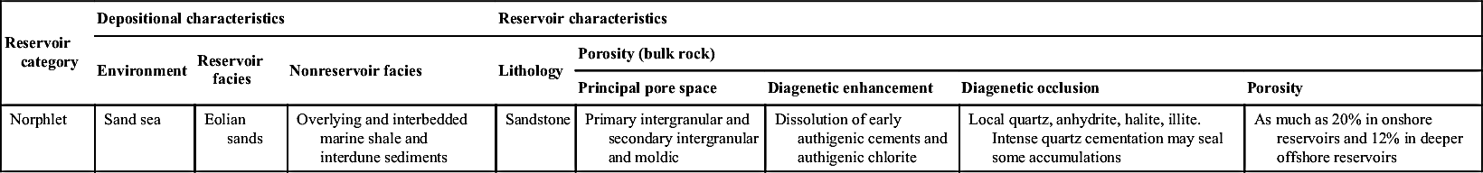
6.11.2.1.1. Norphlet Formation
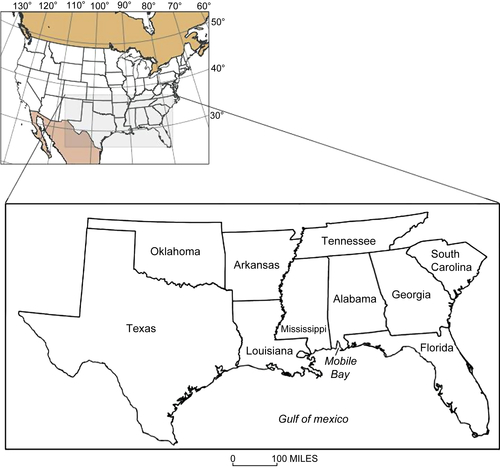
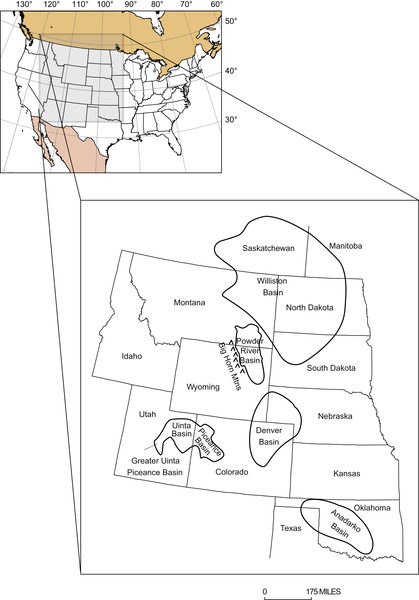
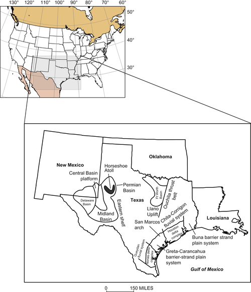
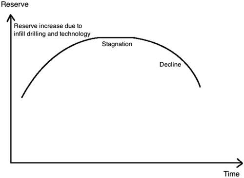
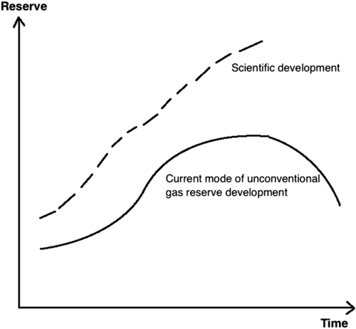
Table 6.25
Norphlet Formation, Gulf of Mexico Basin—Summary of Geological Characteristics and Reserve Growth Potential of Reservoirs
| Reservoir category | Depositional characteristics | Reservoir characteristics | ||||||
| Environment | Reservoir facies | Nonreservoir facies | Lithology | Porosity (bulk rock) | ||||
| Principal pore space | Diagenetic enhancement | Diagenetic occlusion | Porosity | |||||
| Norphlet | Sand sea | Eolian sands | Overlying and interbedded marine shale and interdune sediments | Sandstone | Primary intergranular and secondary intergranular and moldic | Dissolution of early authigenic cements and authigenic chlorite | Local quartz, anhydrite, halite, illite. Intense quartz cementation may seal some accumulations | As much as 20% in onshore reservoirs and 12% in deeper offshore reservoirs |
| Reservoir characteristics–Continued | Source rock | Stratigraphic controls | Structural controls | Oil or gas | |||
| Permeability | Fractures | Reservoir location | Traps or seals | Reservoir location | Traps or seals | ||
| Generally high; as much as 500 mD | May be complexity faulted | Overlying marine shale of Smackover Formation; interbedded or interfingering organic-rich shale in Norphlet Formation | Updip pinchout against basement complex | Overflying shale and interbedded interdune, sabkha, or playa units | Reservoir rocks thicken in basement controlled grabens and are absent or thin over basement controlled highs | Anticlines, faulted anticlines, faults associated with basement structures, and halokinesis of Louann Salt | Dominantly nonassociated gas (cracked) and minor oil |
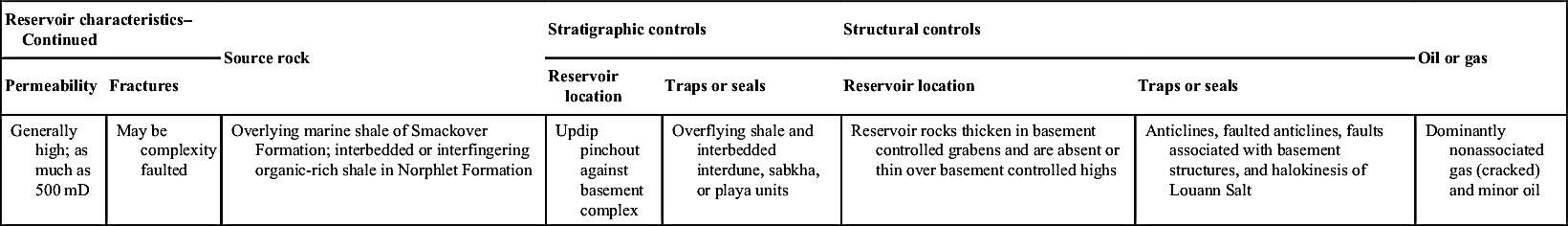
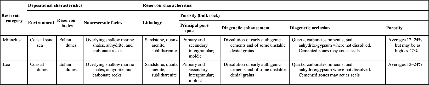
6.11.2.1.2. Minnelusa Formation
Table 6.26
Minnelusa Formation, Powder River Basin—Summary of Geological Characteristics and Reserve Growth Potential of Reservoirs
| Reservoir category | Depositional characteristics | Reservoir characteristics | ||||||
| Environment | Reservoir facies | Nonreservoir facies | Lithology | Porosity (bulk rock) | ||||
| Principal pore space | Diagenetic enhancement | Diagenetic occlusion | Porosity | |||||
| Minnelusa | Coastal sand sea | Eolian dunes | Overlying shallow marine shales, anhydrite, and carbonate rocks | Sandstone, quartz arenite, sublitharenite | Primary and secondary intergranular; moldic | Dissolution of early authigenic cements and of some unstable denial grains | Quartz, carbonates minerals, and anhydrite/gypsum where not dissolved. Cemented zones may act as seals | Averages 12–24% but may be as high as 47% |
| Leo | Coastal dunes | Eolian dunes | Overlying shallow marine shales, anhydrite, and carbonate rocks | Sandstone, quartz arenite, sublitharenite | Primary and secondary intergranular; moldic | Dissolution of early authigenic cements and of some unstable denial grains | Quartz, carbonates minerals, and anhydrite/gypsum where not dissolved. Cemented zones may act as seals | Averages 12–24% |
6.11.2.2. Interconnected Fluvial, Deltaic, and Shallow Marine Reservoirs
6.11.2.2.1. Frio Formation
6.11.2.2.2. Morrow Formation
Table 6.27
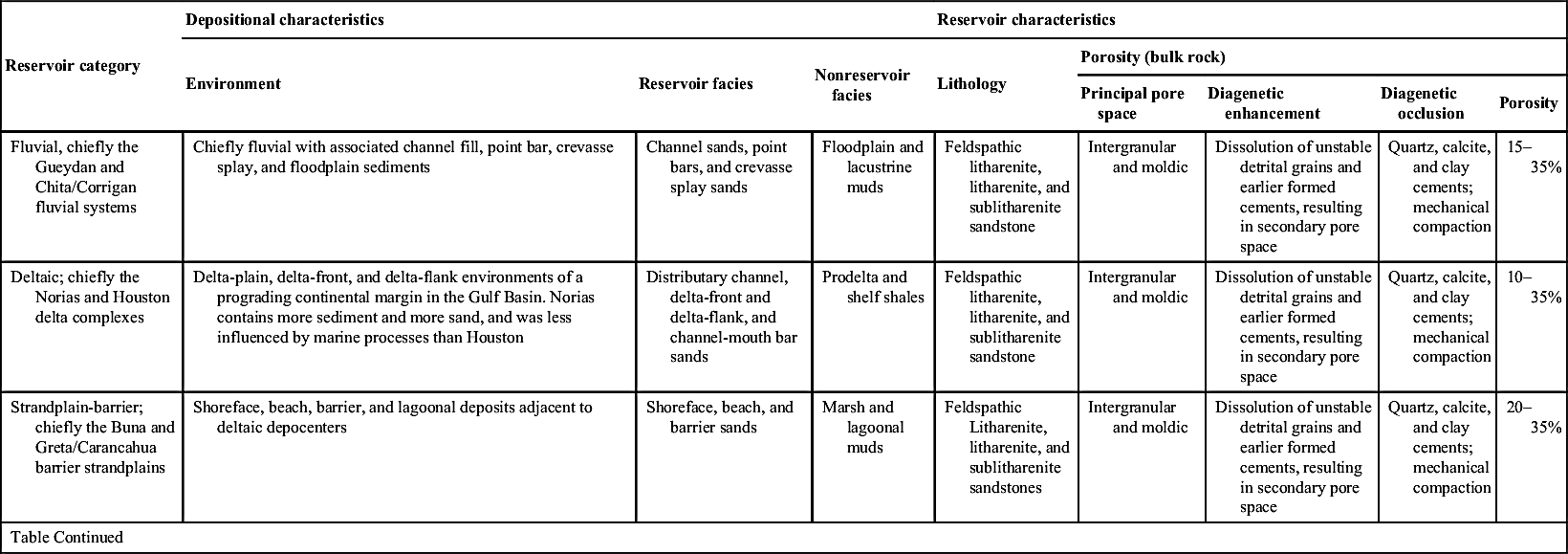
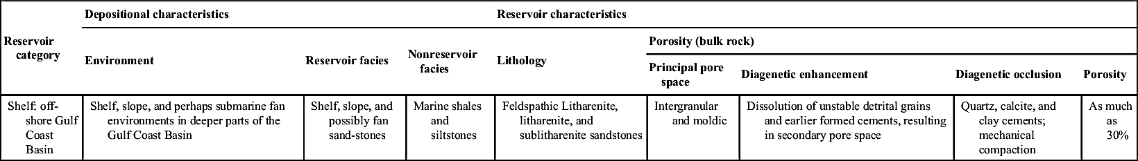
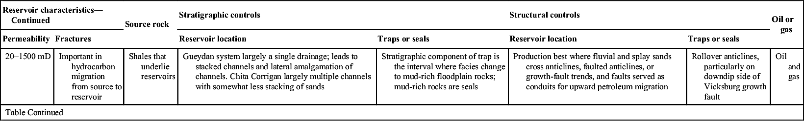
Frio Formation, Gulf of Mexico Basin—Summary of Geological Characteristics and Reserve Growth Potential of Reservoirs
| Reservoir category | Depositional characteristics | Reservoir characteristics | ||||||
| Environment | Reservoir facies | Nonreservoir facies | Lithology | Porosity (bulk rock) | ||||
| Principal pore space | Diagenetic enhancement | Diagenetic occlusion | Porosity | |||||
| Fluvial, chiefly the Gueydan and Chita/Corrigan fluvial systems | Chiefly fluvial with associated channel fill, point bar, crevasse splay, and floodplain sediments | Channel sands, point bars, and crevasse splay sands | Floodplain and lacustrine muds | Feldspathic litharenite, litharenite, and sublitharenite sandstone | Intergranular and moldic | Dissolution of unstable detrital grains and earlier formed cements, resulting in secondary pore space | Quartz, calcite, and clay cements; mechanical compaction | 15–35% |
| Deltaic; chiefly the Norias and Houston delta complexes | Delta-plain, delta-front, and delta-flank environments of a prograding continental margin in the Gulf Basin. Norias contains more sediment and more sand, and was less influenced by marine processes than Houston | Distributary channel, delta-front and delta-flank, and channel-mouth bar sands | Prodelta and shelf shales | Feldspathic litharenite, litharenite, and sublitharenite sandstone | Intergranular and moldic | Dissolution of unstable detrital grains and earlier formed cements, resulting in secondary pore space | Quartz, calcite, and clay cements; mechanical compaction | 10–35% |
| Strandplain-barrier; chiefly the Buna and Greta/Carancahua barrier strandplains | Shoreface, beach, barrier, and lagoonal deposits adjacent to deltaic depocenters | Shoreface, beach, and barrier sands | Marsh and lagoonal muds | Feldspathic Litharenite, litharenite, and sublitharenite sandstones | Intergranular and moldic | Dissolution of unstable detrital grains and earlier formed cements, resulting in secondary pore space | Quartz, calcite, and clay cements; mechanical compaction | 20–35% |
| Table Continued | ||||||||
| Reservoir category | Depositional characteristics | Reservoir characteristics | ||||||
| Environment | Reservoir facies | Nonreservoir facies | Lithology | Porosity (bulk rock) | ||||
| Principal pore space | Diagenetic enhancement | Diagenetic occlusion | Porosity | |||||
| Shelf: off-shore Gulf Coast Basin | Shelf, slope, and perhaps submarine fan environments in deeper parts of the Gulf Coast Basin | Shelf, slope, and possibly fan sand-stones | Marine shales and siltstones | Feldspathic Litharenite, litharenite, and sublitharenite sandstones | Intergranular and moldic | Dissolution of unstable detrital grains and earlier formed cements, resulting in secondary pore space | Quartz, calcite, and clay cements; mechanical compaction | As much as 30% |
| Reservoir characteristics—Continued | Source rock | Stratigraphic controls | Structural controls | Oil or gas | |||
| Permeability | Fractures | Reservoir location | Traps or seals | Reservoir location | Traps or seals | ||
| 20–1500 mD | Important in hydrocarbon migration from source to reservoir | Shales that underlie reservoirs | Gueydan system largely a single drainage; leads to stacked channels and lateral amalgamation of channels. Chita Corrigan largely multiple channels with somewhat less stacking of sands | Stratigraphic component of trap is the interval where facies change to mud-rich floodplain rocks; mud-rich rocks are seals | Production best where fluvial and splay sands cross anticlines, faulted anticlines, or growth-fault trends, and faults served as conduits for upward petroleum migration | Rollover anticlines, particularly on downdip side of Vicksburg growth fault | Oil and gas |
| Table Continued | |||||||
| Reservoir characteristics—Continued | Source rock | Stratigraphic controls | Structural controls | Oil or gas | |||
| Permeability | Fractures | Reservoir location | Traps or seals | Reservoir location | Traps or seals | ||
| 10–2400 mD | Important in hydrocarbon migration from source to reservoir; also juxtapose reservoirs and seals | Shales that underlie or are basinward facies of reservoirs | Abundant sediment supply and single fluvial system input lead to vertically stacked sandy deltaic lobes (Norias), whereas Houston delta fed by several smaller fluvial systems that led to numerous small dispersed lobes with less continuous sands | Stratigraphic component of trap is at abrupt facies changes from reservoir to fine-grained rocks; mud-rich rocks are seals | Syndepositional movement on growth faults and salt diapirs but no thickening of deltaic sediments, including reservoir rocks | Anticlines and faulted anticlines, some of which are associated with growth faults (Noria and Houston) or salt diapirism (Houston); also growth faults juxtapose reservoirs with seals or compartmentalize reservoirs | Associated gas and oil from more proximal parts, and nonassociated gas from more distal parts |
| 8–3500 mD | Important in hydrocarbon migration from source to reservoir; also juxtapose reservoirs and seals | Shales that underlie or are basinward facies of reservoirs | Greater marine influence on Houston delta led to greater redistribution of sands into strandplain systems than on sands that originated in Norias delta | Stratigraphic component of trap is the interval where facies change to mud-rich floodplain rocks; mud-rich rocks are seals | Vertical stacking of sands and strike-parallel orientation of sands greatly influenced by orientation and movement of growth faults | Anticlines, rollover anticlines, and faulted anticlines | Associated gas and oil |
| As much as l500 mD | Important in hydrocarbon migration from source to reservoir; also juxtapose reservoirs and seals | Shales that interbed with or underlie reservoir rocks | Stratigraphic controls on reservoir location unclear | Stratigraphic component of trap is at abrupt change from reservoir to fine-grained rocks; fine-grained rocks serve as seals | Sediment accumulation in submarine canyons or intraslope basins that formed from active faulting or salt diapirs (or both) | Faulted anticlines and salt-related structures. Seals formed by fault-related juxtaposition of reservoirs with impermeable rocks | Largely gas |
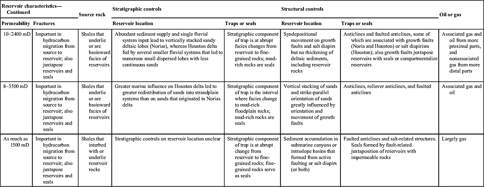
Table 6.28
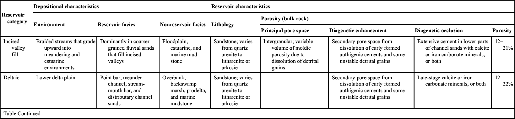
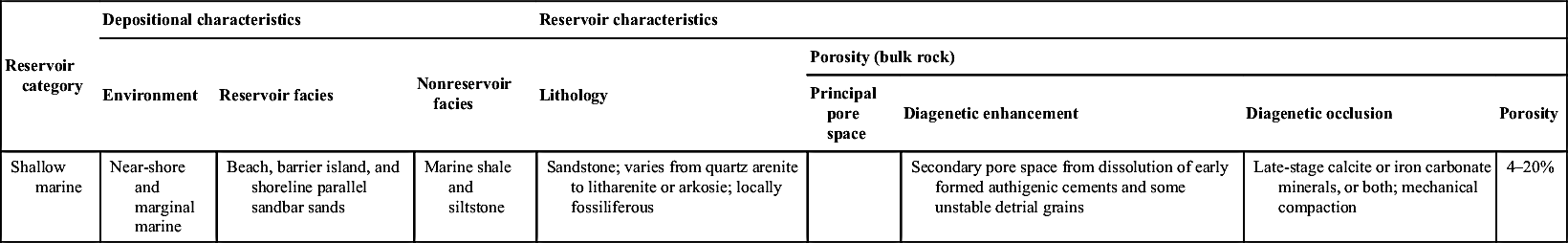
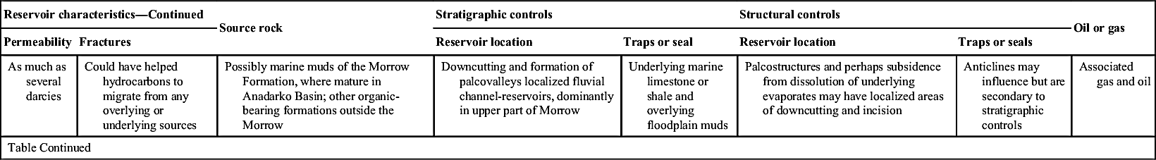
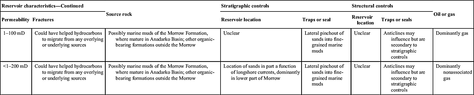
Morrow Formation, Anadarko and Denver Basins—Summary of Geological Characteristics and Reserve Growth Potential of Reservoirs
| Reservoir category | Depositional characteristics | Reservoir characteristics | ||||||
| Environment | Reservoir facies | Nonreservoir facies | Lithology | Porosity (bulk rock) | ||||
| Principal pore space | Diagenetic enhancement | Diagenetic occlusion | Porosity | |||||
| Incised valley fill | Braided streams that grade upward into meandering and estuarine environments | Dominantly in coarser grained fluvial sands that fill incised valleys | Floodplain, estuarine, and marine mud-stone | Sandstone; varies from quartz arenite to litharenite or arkosie | Intergranular; variable volume of moldic porosity due to dissolution of detrital grains | Secondary pore space from dissolution of early formed authigenic cements and some unstable detrital grains | Extensive cement in lower parts of channel sands with calcite or iron carbonate minerals, or both | 12–21% |
| Deltaic | Lower delta plain | Point bar, meander channel, stream-mouth bar, and distributary channel sands | Overbank, backswamp marsh, prodelta, and marine mudstone | Sandstone; varies from quartz arenite to litharenite or arkosie | Secondary pore space from dissolution of early formed authigenic cements and some unstable detrital grains | Late-stage calcite or iron carbonate minerals, or both | 12–22% | |
| Table Continued | ||||||||
| Reservoir category | Depositional characteristics | Reservoir characteristics | ||||||
| Environment | Reservoir facies | Nonreservoir facies | Lithology | Porosity (bulk rock) | ||||
| Principal pore space | Diagenetic enhancement | Diagenetic occlusion | Porosity | |||||
| Shallow marine | Near-shore and marginal marine | Beach, barrier island, and shoreline parallel sandbar sands | Marine shale and siltstone | Sandstone; varies from quartz arenite to litharenite or arkosie; locally fossiliferous | Secondary pore space from dissolution of early formed authigenic cements and some unstable detrial grains | Late-stage calcite or iron carbonate minerals, or both; mechanical compaction | 4–20% | |
| Reservoir characteristics—Continued | Source rock | Stratigraphic controls | Structural controls | Oil or gas | |||
| Permeability | Fractures | Reservoir location | Traps or seal | Reservoir location | Traps or seals | ||
| As much as several darcies | Could have helped hydrocarbons to migrate from any overlying or underlying sources | Possibly marine muds of the Morrow Formation, where mature in Anadarko Basin; other organic-bearing formations outside the Morrow | Downcutting and formation of palcovalleys localized fluvial channel-reservoirs, dominantly in upper part of Morrow | Underlying marine limestone or shale and overlying floodplain muds | Palcostructures and perhaps subsidence from dissolution of underlying evaporates may have localized areas of downcutting and incision | Anticlines may influence but are secondary to stratigraphic controls | Associated gas and oil |
| Table Continued | |||||||
| Reservoir characteristics—Continued | Source rock | Stratigraphic controls | Structural controls | Oil or gas | |||
| Permeability | Fractures | Reservoir location | Traps or seal | Reservoir location | Traps or seals | ||
| 1–100 mD | Could have helped hydrocarbons to migrate from any overlying or underlying sources | Possibly marine muds of the Morrow Formation, where mature in Anadarko Basin; other organic-bearing formations outside the Morrow | Unclear | Lateral pinchout of sands into fine-grained marine muds | Unclear | Anticlines may influence but are secondary to stratigraphic controls | Dominantly gas |
| <1–200 mD | Could have helped hydrocarbons to migrate from any overlying or underlying sources | Possibly marine muds of the Morrow Formation, where mature in Anadarko Basin; other organic-bearing formations outside the Morrow | Location of sands in part a function of longshore currents, dominantly in lower part of Morrow | Lateral pinchout of sands into fine-grained marine muds | Unclear | Anticlines may influence but are secondary to stratigraphic controls | Dominantly nonassociated gas |
6.11.2.3. Deeper Marine Shales
6.11.2.3.1. Barnett Shale
6.11.2.3.2. Bakken Formation
Table 6.29
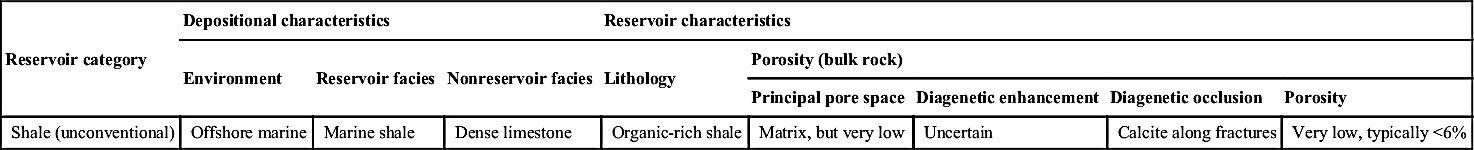
Barnett Shale, Fort Worth Basin—Summary of Geological Characteristics and Reserve-Growth Potential of Reservoirs
| Reservoir category | Depositional characteristics | Reservoir characteristics | ||||||
| Environment | Reservoir facies | Nonreservoir facies | Lithology | Porosity (bulk rock) | ||||
| Principal pore space | Diagenetic enhancement | Diagenetic occlusion | Porosity | |||||
| Shale (unconventional) | Offshore marine | Marine shale | Dense limestone | Organic-rich shale | Matrix, but very low | Uncertain | Calcite along fractures | Very low, typically <6% |
| Reservoir characteristics—Continued | Source rock | Stratigraphic controls | Structural controls | Oil or gas | ||||
| Permeability | Fractures | Reservoir location | Traps or seals | Reservoir location | Traps or seals | |||
| Very low, typically in the range of nanodarcies | Naturally fractured in deeper parts of basin and over structures; fractures reduce productivity | Organic-rich shale in the Barnett that also serves as reservoir rock | Uncertain | Gas trapped by fine grained nature of shale reservoir | Best production away from fractured areas | Open faults tended to leak gas out of formation, whereas calcite filled faults prevented gas migration | Non-associated gas | |
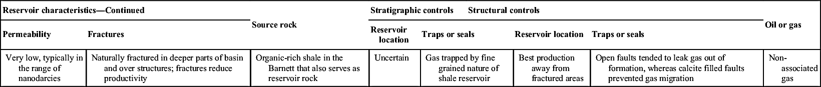
Table 6.30
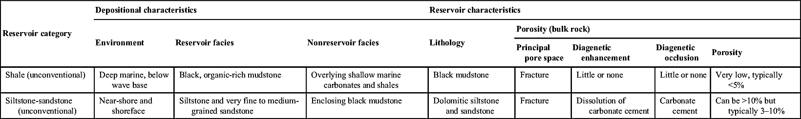
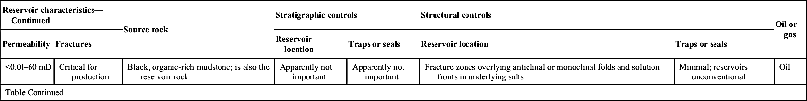
Bakken Formation, Williston Basin—Summary of Geological Characteristics and Reserve-Growth Potential of Reservoirs
| Reservoir category | Depositional characteristics | Reservoir characteristics | ||||||
| Environment | Reservoir facies | Nonreservoir facies | Lithology | Porosity (bulk rock) | ||||
| Principal pore space | Diagenetic enhancement | Diagenetic occlusion | Porosity | |||||
| Shale (unconventional) | Deep marine, below wave base | Black, organic-rich mudstone | Overlying shallow marine carbonates and shales | Black mudstone | Fracture | Little or none | Little or none | Very low, typically <5% |
| Siltstone-sandstone (unconventional) | Near-shore and shoreface | Siltstone and very fine to medium-grained sandstone | Enclosing black mudstone | Dolomitic siltstone and sandstone | Fracture | Dissolution of carbonate cement | Carbonate cement | Can be >10% but typically 3–10% |
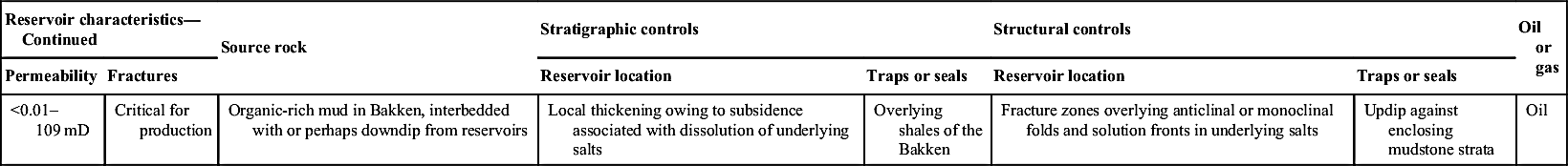
| Reservoir characteristics—Continued | Source rock | Stratigraphic controls | Structural controls | Oil or gas | |||
| Permeability | Fractures | Reservoir location | Traps or seals | Reservoir location | Traps or seals | ||
| <0.0l–60 mD | Critical for production | Black, organic-rich mudstone; is also the reservoir rock | Apparently not important | Apparently not important | Fracture zones overlying anticlinal or monoclinal folds and solution fronts in underlying salts | Minimal; reservoirs unconventional | Oil |
| Table Continued | |||||||
| Reservoir characteristics—Continued | Source rock | Stratigraphic controls | Structural controls | Oil or gas | |||
| Permeability | Fractures | Reservoir location | Traps or seals | Reservoir location | Traps or seals | ||
| <0.01–109 mD | Critical for production | Organic-rich mud in Bakken, interbedded with or perhaps downdip from reservoirs | Local thickening owing to subsidence associated with dissolution of underlying salts | Overlying shales of the Bakken | Fracture zones overlying anticlinal or monoclinal folds and solution fronts in underlying salts | Updip against enclosing mudstone strata | Oil |
6.11.2.4. Marine Carbonate Reservoirs
6.11.2.4.1. Ellenburger Group
Table 6.31
Ellenburger Group, Permian Basin—Summary of Geological Characteristics and Reserve-Growth Potential of Reservoirs
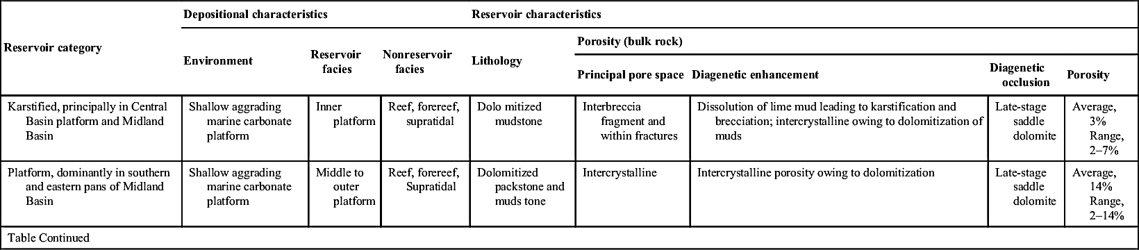
| Reservoir category | Depositional characteristics | Reservoir characteristics | ||||||
| Environment | Reservoir facies | Nonreservoir facies | Lithology | Porosity (bulk rock) | ||||
| Principal pore space | Diagenetic enhancement | Diagenetic occlusion | Porosity | |||||
| Karstified, principally in Central Basin platform and Midland Basin | Shallow aggrading marine carbonate platform | Inner platform | Reef, forereef, supratidal | Dolo mitized mudstone | Interbreccia fragment and within fractures | Dissolution of lime mud leading to karstification and brecciation; intercrystalline owing to dolomitization of muds | Late-stage saddle dolomite | Average, 3% Range, 2–7% |
| Platform, dominantly in southern and eastern pans of Midland Basin | Shallow aggrading marine carbonate platform | Middle to outer platform | Reef, forereef, Supratidal | Dolomitized packstone and muds tone | Intercrystalline | Intercrystalline porosity owing to dolomitization | Late-stage saddle dolomite | Average, 14% Range, 2–14% |
| Table Continued | ||||||||
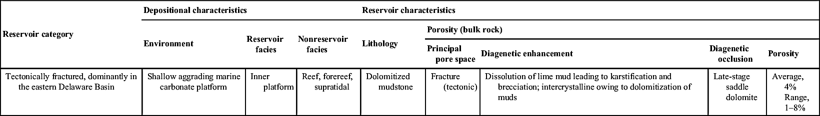
| Reservoir category | Depositional characteristics | Reservoir characteristics | ||||||
| Environment | Reservoir facies | Nonreservoir facies | Lithology | Porosity (bulk rock) | ||||
| Principal pore space | Diagenetic enhancement | Diagenetic occlusion | Porosity | |||||
| Tectonically fractured, dominantly in the eastern Delaware Basin | Shallow aggrading marine carbonate platform | Inner platform | Reef, forereef, supratidal | Dolomitized mudstone | Fracture (tectonic) | Dissolution of lime mud leading to karstification and brecciation; intercrystalline owing to dolomitization of muds | Late-stage saddle dolomite | Average, 4% Range, 1–8% |
| Reservoir characteristics—Continued | Source rock | Stratigraphic controls | Structural controls | Oil or gas | |||
| Permeability | Fractures | Reservoir location | Traps or seals | Reservoir location | Traps or seals | ||
| Mean, 32-mD Range, 2–750 mD | Channeled pore fluids that allowed vertical infiltration of dissolving waters into various stratigraphic horizons to promote karstification | Overlying Ordo vician Simpson Group | Lime muds remaining after early dolomitization, which became horizons subject to dissolution leading to karstification | Traps and seals include overlying Simpson Group and unkarsted Ellenburger dolomite. Seals also include impermeable cave-fill sediments and collapse zone adjacent to reservoirs | Anticlines, faulted anticlines, and fault-bounded anticlines | Uncertain | Principally oil with some associated gas and gas condensate |
| Table Continued | |||||||
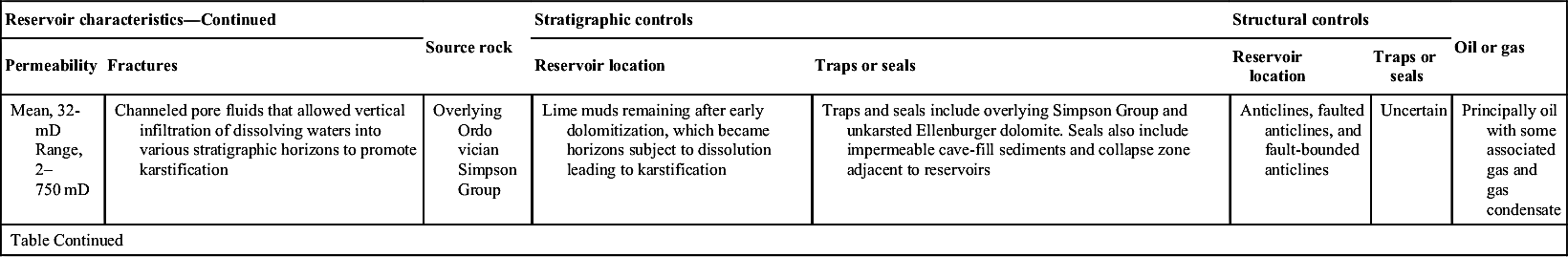
| Reservoir characteristics—Continued | Source rock | Stratigraphic controls | Structural controls | Oil or gas | |||
| Permeability | Fractures | Reservoir location | Traps or seals | Reservoir location | Traps or seals | ||
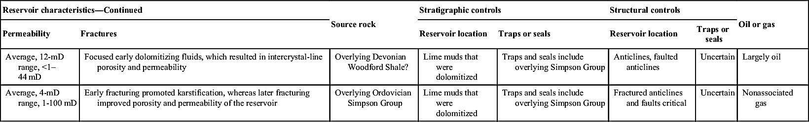
| Average, 12-mD range, <1–44 mD | Focused early dolomitizing fluids, which resulted in intercrystal-line porosity and permeability | Overlying Devonian Woodford Shale? | Lime muds that were dolomitized | Traps and seals include overlying Simpson Group | Anticlines, faulted anticlines | Uncertain | Largely oil |
| Average, 4-mD range, 1-100 mD | Early fracturing promoted karstification, whereas later fracturing improved porosity and permeability of the reservoir | Overlying Ordovician Simpson Group | Lime muds that were dolomitized | Traps and seals include overlying Simpson Group | Fractured anticlines and faults critical | Uncertain | Nonassociated gas |
6.11.2.4.2. Smackover Formation
6.11.2.5. Submarine Fan Reservoir
6.11.2.5.1. Spraberry Formation
Table 6.32
Smackover Formation, Gulf Coast region—Summary of Geological Characteristics and Reserve-Growth Potential of Reservoirs
| Reservoir category | Depositional characteristics | Reservoir characteristics | ||||||
| Environment | Reservoir facies | Nonreservoir facies | Lithology | Porosity (bulk rock) | ||||
| Principal pore space | Diagenetic enhancement | Diagenetic occlusion | Porosity | |||||
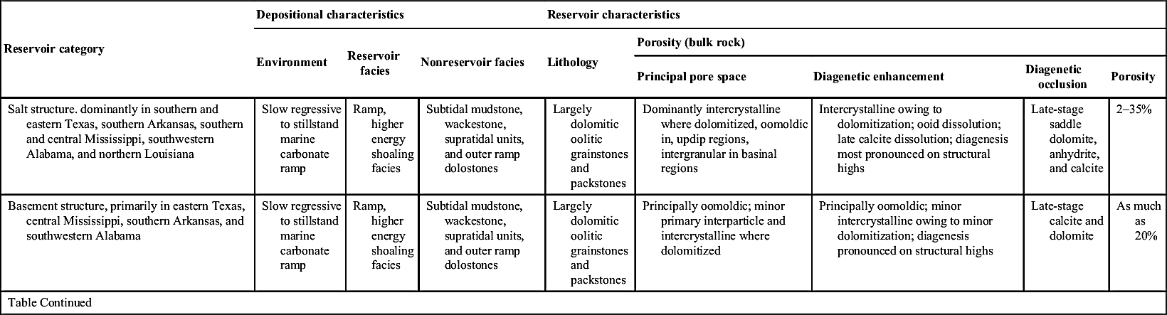
| Salt structure. dominantly in southern and eastern Texas, southern Arkansas, southern and central Mississippi, southwestern Alabama, and northern Louisiana | Slow regressive to stillstand marine carbonate ramp | Ramp, higher energy shoaling facies | Subtidal mudstone, wackestone, supratidal units, and outer ramp dolostones | Largely dolomitic oolitic grainstones and packstones | Dominantly intercrystalline where dolomitized, oomoldic in, updip regions, intergranular in basinal regions | Intercrystalline owing to dolomitization; ooid dissolution; late calcite dissolution; diagenesis most pronounced on structural highs | Late-stage saddle dolomite, anhydrite, and calcite | 2–35% |
| Basement structure, primarily in eastern Texas, central Mississippi, southern Arkansas, and southwestern Alabama | Slow regressive to stillstand marine carbonate ramp | Ramp, higher energy shoaling facies | Subtidal mudstone, wackestone, supratidal units, and outer ramp dolostones | Largely dolomitic oolitic grainstones and packstones | Principally oomoldic; minor primary interparticle and intercrystalline where dolomitized | Principally oomoldic; minor intercrystalline owing to minor dolomitization; diagenesis pronounced on structural highs | Late-stage calcite and dolomite | As much as 20% |
| Table Continued | ||||||||
| Reservoir category | Depositional characteristics | Reservoir characteristics | ||||||
| Environment | Reservoir facies | Nonreservoir facies | Lithology | Porosity (bulk rock) | ||||
| Principal pore space | Diagenetic enhancement | Diagenetic occlusion | Porosity | |||||
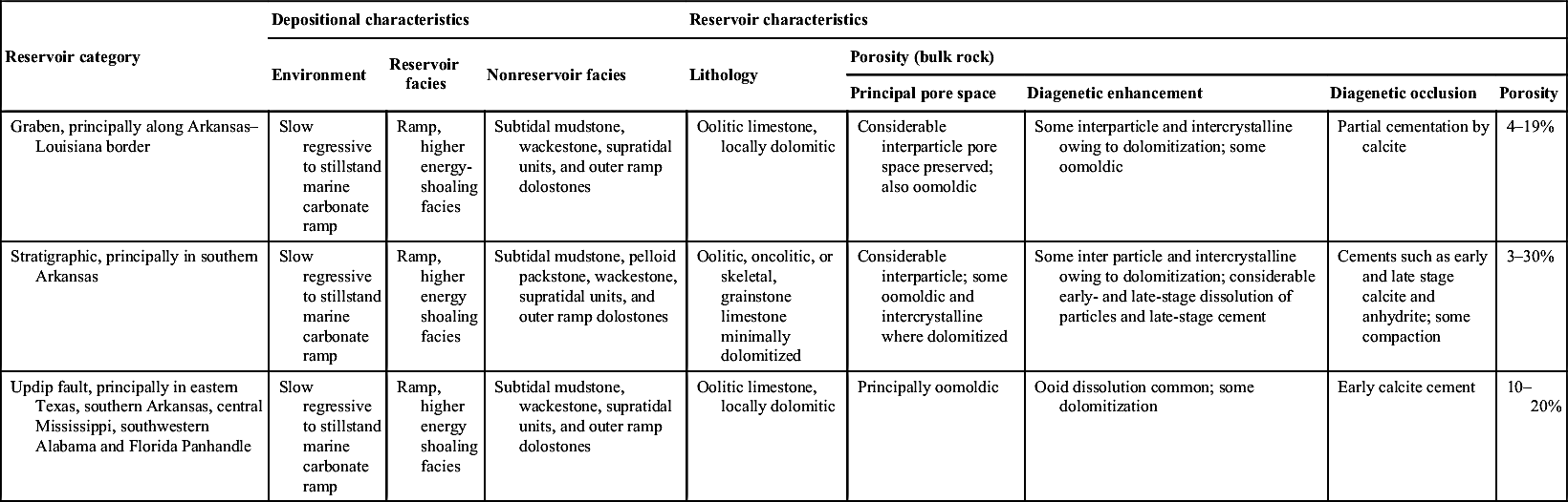
| Graben, principally along Arkansas–Louisiana border | Slow regressive to stillstand marine carbonate ramp | Ramp, higher energy-shoaling facies | Subtidal mudstone, wackestone, supratidal units, and outer ramp dolostones | Oolitic limestone, locally dolomitic | Considerable interparticle pore space preserved; also oomoldic | Some interparticle and intercrystalline owing to dolomitization; some oomoldic | Partial cementation by calcite | 4–19% |
| Stratigraphic, principally in southern Arkansas | Slow regressive to stillstand marine carbonate ramp | Ramp, higher energy shoaling facies | Subtidal mudstone, pelloid packstone, wackestone, supratidal units, and outer ramp dolostones | Oolitic, oncolitic, or skeletal, grainstone limestone minimally dolomitized | Considerable interparticle; some oomoldic and intercrystalline where dolomitized | Some inter particle and intercrystalline owing to dolomitization; considerable early- and late-stage dissolution of particles and late-stage cement | Cements such as early and late stage calcite and anhydrite; some compaction | 3–30% |
| Updip fault, principally in eastern Texas, southern Arkansas, central Mississippi, southwestern Alabama and Florida Panhandle | Slow regressive to stillstand marine carbonate ramp | Ramp, higher energy shoaling facies | Subtidal mudstone, wackestone, supratidal units, and outer ramp dolostones | Oolitic limestone, locally dolomitic | Principally oomoldic | Ooid dissolution common; some dolomitization | Early calcite cement | 10–20% |
| Reservoir characteristics—Continued | Source rock | Stratigraphic controls | Structural controls | Oil or gas | |||
| Permeability | Fractures | Reservoir location | Traps or seals | Reservoir location | Traps or seals | ||
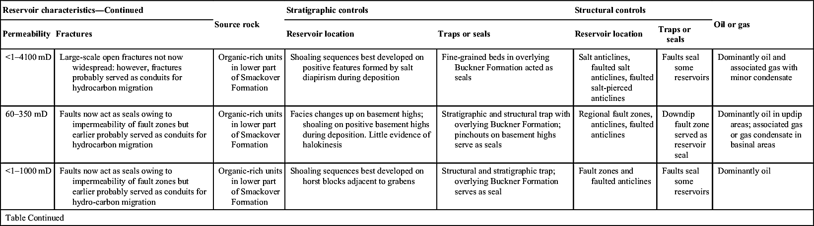
| <1–4100 mD | Large-scale open fractures not now widespread: however, fractures probably served as conduits for hydrocarbon migration | Organic-rich units in lower part of Smackover Formation | Shoaling sequences best developed on positive features formed by salt diapirism during deposition | Fine-grained beds in overlying Buckner Formation acted as seals | Salt anticlines, faulted salt anticlines, faulted salt-pierced anticlines | Faults seal some reservoirs | Dominantly oil and associated gas with minor condensate |
| 60–350 mD | Faults now act as seals owing to impermeability of fault zones but earlier probably served as conduits for hydrocarbon migration | Organic-rich units in lower part of Smackover Formation | Facies changes up on basement highs; shoaling on positive basement highs during deposition. Little evidence of halokinesis | Stratigraphic and structural trap with overlying Buckner Formation; pinchouts on basement highs serve as seals | Regional fault zones, anticlines, faulted anticlines | Downdip fault zone served as reservoir seal | Dominantly oil in updip areas; associated gas or gas condensate in basinal areas |
| <1–1000 mD | Faults now act as seals owing to impermeability of fault zones but earlier probably served as conduits for hydro-carbon migration | Organic-rich units in lower part of Smackover Formation | Shoaling sequences best developed on horst blocks adjacent to grabens | Structural and stratigraphic trap; overlying Buckner Formation serves as seal | Fault zones and faulted anticlines | Faults seal some reservoirs | Dominantly oil |
| Table Continued | |||||||
| Reservoir characteristics—Continued | Source rock | Stratigraphic controls | Structural controls | Oil or gas | |||
| Permeability | Fractures | Reservoir location | Traps or seals | Reservoir location | Traps or seals | ||
| 1–250 mD | Faults probably- served as conduits for hydrocarbon migration | Organic-rich units in lower part of Smackover Formation | Facies changes and regressive units overlying reservoirs | Structural and stratigraphic trap; overlying Buckner Formation serves as seal | Likely; structures limited deposition of reservoir rocks or facilitated pinchouts | Faults seal some reservoirs | Dominantly oil; some associated gas |
| 3–280 mD | Faults now act as seals owing to impermeability of fault zones but earlier probably served as conduits for hydrocarbon migration | Organic-rich units in lower part of Smackover Formation | Near updip limit of Smackover deposition | Dominantly structural trap; fault systems serve as seals | Uplift on faults juxtaposed reservoirs and impermeable beds | Fault zones | Dominantly oil; some gas or gas condensate |
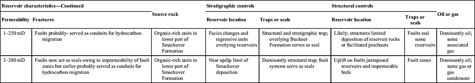
Table 6.33
Spraberry Formation, Midland Basin—Summary of Geological Characteristics and Reserve-Growth Potential of Reservoirs
| Reservoir category | Depositional characteristics | Reservoir characteristics | ||||||
| Environment | Reservoir facies | Nonreservoir facies | Lithology | Porosity (bulk rock) | ||||
| Principal pore space | Diagenetic enhancement | Diagenetic occlusion | Porosity | |||||
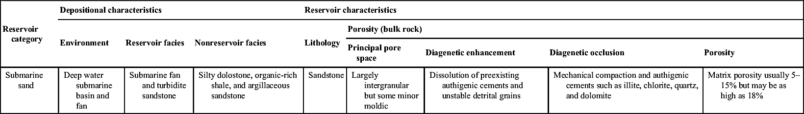
| Submarine sand | Deep water submarine basin and fan | Submarine fan and turbidite sandstone | Silty dolostone, organic-rich shale, and argillaceous sandstone | Sandstone | Largely intergranular but some minor moldic | Dissolution of preexisting authigenic cements and unstable detrital grains | Mechanical compaction and authigenic cements such as illite, chlorite, quartz, and dolomite | Matrix porosity usually 5–15% but may be as high as 18% |
| Reservoir characteristics–Continued | Source rock | Stratigraphic controls | Structural controls | Oil or gas | |||
| Permeability | Fractures | Reservoir location | Traps or seals | Reservoir location | Traps or seals | ||
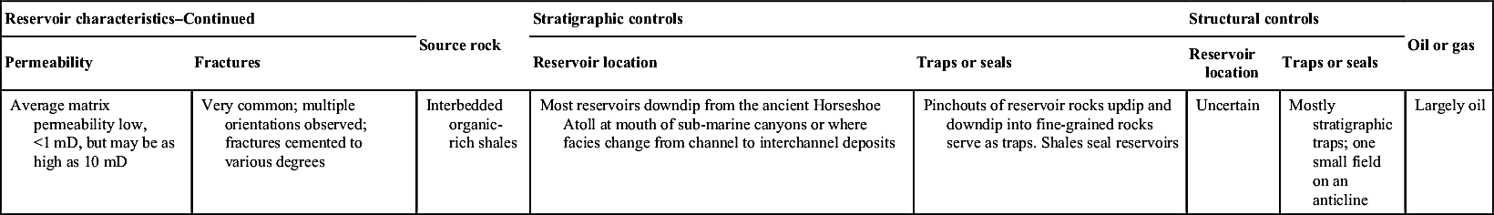
| Average matrix permeability low, <1 mD, but may be as high as 10 mD | Very common; multiple orientations observed; fractures cemented to various degrees | Interbedded organic-rich shales | Most reservoirs downdip from the ancient Horseshoe Atoll at mouth of sub-marine canyons or where facies change from channel to interchannel deposits | Pinchouts of reservoir rocks updip and downdip into fine-grained rocks serve as traps. Shales seal reservoirs | Uncertain | Mostly stratigraphic traps; one small field on an anticline | Largely oil |
6.11.2.6. Fluvial Reservoir
6.11.2.6.1. Wasatch Formation
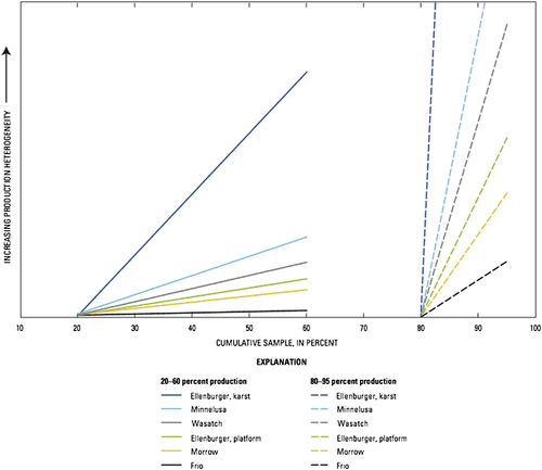
6.11.3. Quantitative Measures of Well Production Variability
Table 6.34
Wasatch Formation, Uinta-Piceance Basin—Summary of Geological Characteristics and Reserve-Growth Potential of Reservoirs
| Reservoir category | Depositional characteristics | Reservoir characteristics | ||||||
| Environment | Reservoir facies | Nonreservoir facies | Lithology | Porosity (bulk rock) | ||||
| Principal pore space | Diagenetic enhancement | Diagenetic occlusion | Porosity | |||||
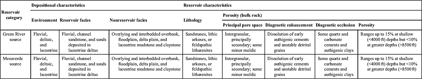
| Green River source | Fluvial, deltaic, and lacustrine | Fluvial, channel sandstone, and sands deposited in lacustrine deltas | Overlying and interbedded overbank, floodplain, delta plain, and lacustrine mudstone and claystone | Sandstones, lithic arkoses, or feldspathic litharenites | Intergranular, principally secondary; some minor moldic | Dissolution of early authigenic cements and unstable detrital grains | Some quartz and carbonate cements and authigenic clays | Ranges up to 15% at shallow (<4000 ft) depths but <10% at greater depths (>8500 ft) |
| Mesaverde source | Fluvial, deltaic, and lacustrine | Fluvial, channel sandstone, and sands deposited in lacustrine deltas | Overlying and interbedded overbank, floodplain, delta plain, and lacustrine mudstone and claystone | Sandstones, lithic arkoses, or feldspathic litharenites | Intergranular, principally secondary; some minor moldic | Dissolution of early authigenic cements and unstable detrital grains | Some quartz and carbonate cements and authigenic clays | Ranges up to 15% at shallow (<4000 ft) depths but <10% at greater depths (>8500 ft) |
| Reservoir characteristics–continued | Source rock | Stratigraphics controls | Structural controls | Oil or gas | |||
| Permeability | Fractures | Reservoir location | Traps or seals | Reservoir location | Traps or seals | ||
| Generally low; as much as 40 mD but commonly <0.1 mD | Reservoirs may be complexly faulted; faults allow production | Organic-rich lacustrine mad-stones of Green River Formation, which largely interfingers with the Wasatch | Reservoir rocks deposited adjacent to and in deltas within ancient Lake Uinta | Overlying and interbedded shales, mudstones, and claystones trap and seal reservoirs | Uncertain | Secondary to stratigraphic traps or seals | Dominantly oil; some associated gas |
| Generally low; as much as 40 mD but commonly <0.1 mD | Reservoirs may be complexly faulted; faults allow production; migration along fractures | Coals and organic-rich shale of the Mesaverde Group, which underlies the Wasatch | Reservoir rocks deposited adjacent to and in deltas within ancient Lake Uinta | Overlying and interbedded shales, mudstones, and claystones trap and seal reservoirs | In areas where gas could migrate up fractures that cut from source to reservoir rocks | Secondary to stratigraphic traps or seals | Nonassociated gas |
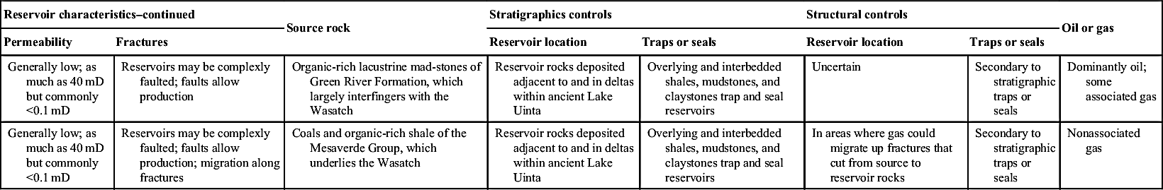
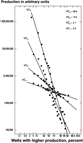
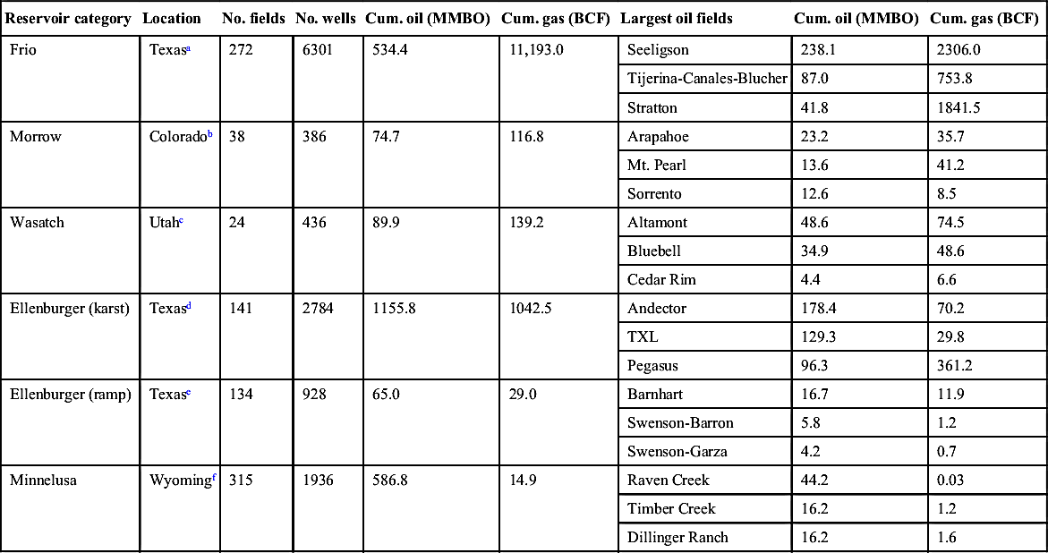
Table 6.35
Location of, Number of Fields and Wells in, Cumulative Production of, and Largest Fields in Each Reservoir Category Analyzed in This Study
| Reservoir category | Location | No. fields | No. wells | Cum. oil (MMBO) | Cum. gas (BCF) | Largest oil fields | Cum. oil (MMBO) | Cum. gas (BCF) |
| Frio | Texasa | 272 | 6301 | 534.4 | 11,193.0 | Seeligson | 238.1 | 2306.0 |
| Tijerina-Canales-Blucher | 87.0 | 753.8 | ||||||
| Stratton | 41.8 | 1841.5 | ||||||
| Morrow | Coloradob | 38 | 386 | 74.7 | 116.8 | Arapahoe | 23.2 | 35.7 |
| Mt. Pearl | 13.6 | 41.2 | ||||||
| Sorrento | 12.6 | 8.5 | ||||||
| Wasatch | Utahc | 24 | 436 | 89.9 | 139.2 | Altamont | 48.6 | 74.5 |
| Bluebell | 34.9 | 48.6 | ||||||
| Cedar Rim | 4.4 | 6.6 | ||||||
| Ellenburger (karst) | Texasd | 141 | 2784 | 1155.8 | 1042.5 | Andector | 178.4 | 70.2 |
| TXL | 129.3 | 29.8 | ||||||
| Pegasus | 96.3 | 361.2 | ||||||
| Ellenburger (ramp) | Texase | 134 | 928 | 65.0 | 29.0 | Barnhart | 16.7 | 11.9 |
| Swenson-Barron | 5.8 | 1.2 | ||||||
| Swenson-Garza | 4.2 | 0.7 | ||||||
| Minnelusa | Wyomingf | 315 | 1936 | 586.8 | 14.9 | Raven Creek | 44.2 | 0.03 |
| Timber Creek | 16.2 | 1.2 | ||||||
| Dillinger Ranch | 16.2 | 1.6 |