
Chapter 3. Wireless Network Physical Architecture
3.1. Wired Network Topologies—A Refresher
The topology of a wired network refers to the physical configuration of links between networked devices or nodes, where each node may be a computer, an end-user device such as a printer or scanner, or some other piece of network hardware such as a hub, switch or router.
The building block from which different topologies are constructed is the simple point-to-point wired link between two nodes, shown in Figure 3.1. Repeating this element results in the two simplest topologies for wired networks—bus and ring.
Figure 3.1. Point-to-point, bus and ring topologies
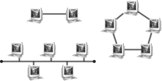
For the ring topology, there are two possible variants depending on whether the inter-node links are simplex (one-way) or duplex (two-way). In the simplex case, each inter-node link has a transmitter at one end and a receiver at the other, and messages circulate in one direction around the ring, while in the duplex case each link has both transmitter and receiver (a so-called transceiver) at each end, and messages can circulate in either direction.
Bus and ring topologies are susceptible to single-point failures, where a single broken link can isolate sections of a bus network or halt all traffic in the case of a ring.
The step that opens up new possibilities is the introduction of specialized network hardware nodes designed to control the flow of data between other networked devices. The simplest of these is the passive hub, which is the central connection point for LAN cabling in star and tree topologies, as shown in Figure 3.2. An active hub, also known as a repeater, is a variety of passive hub that also amplifies the data signal to improve signal strength over long network connections.
Figure 3.2. Star and tree topologies
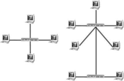
For some PAN technologies, such as USB, star and tree topologies can be built without the need for specialized hardware, because of the daisy-chaining capability of individual devices.
An active or passive hub in a star topology LAN transmits every received data packet to every connected device. Each device checks every packet and decodes those identified by the device’s MAC address. The disadvantage of this arrangement is that the bandwidth of the network is shared among all devices, as shown in Figure 3.3. For example, if two PCs are connected through a 10 Mbps passive hub, each will have on average 5 Mbps of bandwidth available to it.
Figure 3.3. A passive hub in a physical star network
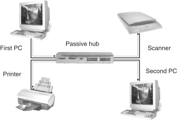
If the first PC is transmitting data, the hub relays the data packets on to all other devices in the network. Any other device on the network will have to wait its turn to transmit data.
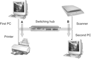
A switching hub (or simply a switch) overcomes this bandwidth sharing limitation by only transmitting a data packet to the device to which it is addressed. Compared to a non-switching hub, this requires increased memory and processing capability, but results in a significant improvement in network capacity.
The first PC (Figure 3.4) is transmitting data stream A to the printer and the switch directs these data packets only to the addressed device. At the same time, the scanner is sending data stream B to the second PC. The switch is able to process both data streams concurrently, so that the full network bandwidth is available to every device.
Figure 3.4. Switching hub in physical star network
3.2. Wireless Network Topologies
3.2.1. Point-to-Point Connections
The simple point-to-point connection shown in Figure 3.1 is probably more common in wireless than in wired networks, since it can be found in a wide variety of different wireless situations, such as:
- peer-to-peer or ad-hoc Wi-Fi connections
- wireless MAN back-haul provision
- LAN wireless bridging
- Bluetooth
- IrDA
3.2.2. Star Topologies in Wireless Networks
In wireless networks the node at the center of a star topology (Figure 3.5), whether it is a WiMAX base station, Wi-Fi access point, Bluetooth Master device or a ZigBee PAN coordinator, plays a similar role to the hub in a wired network. The different wireless networking technologies require and enable a wide range of different functions to be performed by these central control nodes.
Figure 3.5. Star topologies in wireless networks

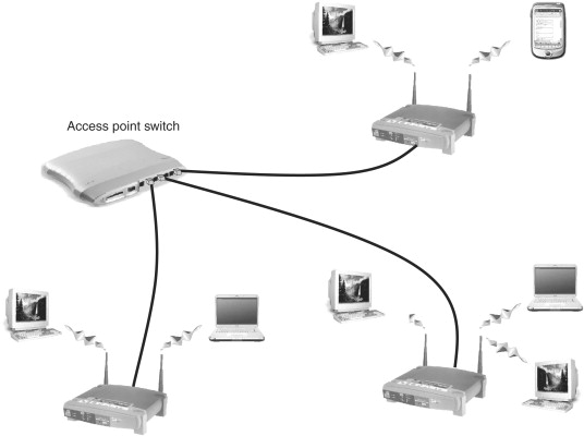
The fundamentally different nature of the wireless medium means that the distinction between switching and nonswitching hubs is generally not relevant for control nodes in wireless networks, since there is no direct wireless equivalent of a separate wire to each device. The wireless LAN switch or controller (Figure 3.6), described in Section 3.3.3, is a wired network device that switches data to the access point that is serving the addressed destination station of each packet.
Figure 3.6. A tree topology using a wireless access point switch
The exception to this general rule arises when base stations or access point devices are able to spatially separate individual stations or groups of stations using sector or array antennas. Figure 3.7 shows a wireless MAN example, with a switch serving four base station transmitters each using a 90° sector antenna.
Figure 3.7. Switched star wireless MAN topology
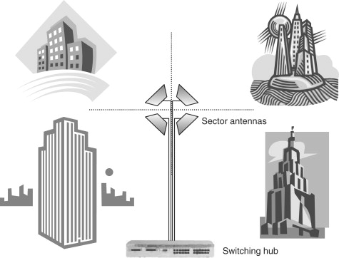
With this configuration, the overall wireless MAN throughput is multiplied by the number of transmitters, similar to the case of the wired switching hub shown in Figure 3.4.
In the wireless LAN case, a similar spatial separation can be achieved using a new class of device called an access point array, described in Section 3.3.5, which combines a wireless LAN controller with an array of sector antennas to multiply network capacity. The general technique of multiplying network throughput by addressing separate spatial zones or propagation paths is known as space division multiplexing and finds its most remarkable application in MIMO radio.
3.2.3. Mesh Networks
Mesh networks, also known as mobile ad hoc networks (MANETs), are local or metropolitan area networks in which nodes are mobile and communicate directly with adjacent nodes without the need for central controlling devices. The topology of a mesh, shown generically in Figure 3.8, can be constantly changing, as nodes enter and leave the network, and data packets are forwarded from node-to-node towards their destination in a process called hopping.
Figure 3.8. Mesh network topology
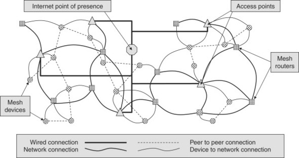
The data routing function is distributed throughout the entire mesh rather than being under the control of one or more dedicated devices. This is similar to the way that data travels around the Internet, with a packet hopping from one device to another until it reaches its destination, although in mesh networks, the routing capabilities are included in every node rather than just in dedicated routers.
This dynamic routing capability requires each device to communicate its routing information to every device it connects with, and to update this as nodes move within, join and leave the mesh.
This distributed control and continuous reconfiguration allows for rapid rerouting around overloaded, unreliable or broken paths, allowing mesh networks to be self-healing and very reliable, provided that the density of nodes is sufficiently high to allow alternative paths. A key challenge in the design of the routing protocol is to achieve this continuous reconfiguration capability with a manageable overhead in terms of data bandwidth taken up by routing information messages.
The multiplicity of paths in a mesh network has a similar impact on total network throughput as the multiple paths shown in Figures 3.4 and 3.7 for the case of wired network switches and sectorized wireless networks. Mesh network capacity will grow as the number of nodes, and therefore the number of usable alternative paths, grow, so that capacity can be increased simply by adding more nodes to the mesh.
As well as the problem of efficiently gathering and updating routing information, mesh networks face several additional technical challenges such as:
- Wireless link reliability—a packet error rate that may be tolerable over a single hop in an hub and spokes configuration will quickly compound over multiple hops, limiting the size to which a mesh can grow and remain effective.
- Seamless roaming—seamless connection and reconnection of moving nodes has not been a requirement in most wireless network standards, although 802.11 Task Groups TGr and TGs are addressing this.
- Security—how to authenticate users in a network with no stable infrastructure?
From a practical standpoint, the self-configuring, self-optimizing and self-healing characteristics of mesh networks eliminate many of the management and maintenance tasks associated with large-scale wireless network deployments.
ZigBee is one standard which explicitly supports mesh networks and the IEEE 802.11 Task Group TGs is in the process of developing a standard which addresses WLAN mesh networks. Two industry bodies have already been established to promote 802.11s mesh proposals, the Wi-Mesh Alliance and SEEMesh (Simple, Efficient and Extensible Mesh).
3.3. Wireless LAN Devices
3.3.1. Wireless Network Interface Cards
The wireless network interface card (NIC) turns a device such as a PDA, laptop or desktop computer into a wireless station and enables the device to communicate with other stations in a peer-to-peer network or with an access point.
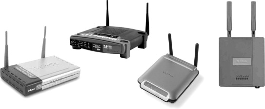
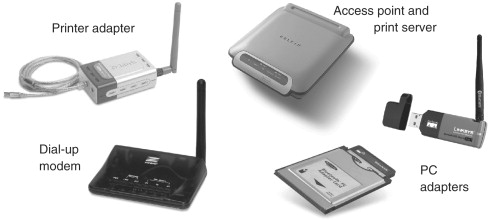
Wireless NICs are available in a variety of form factors (Figure 3.9), including PC (Type II PCMCIA) and PCI cards, as well as external USB devices and USB dongles, or compact flash for PDAs. Most wireless NICs have integrated antennas, but a few manufacturers provide NICs with an external antenna connection or detachable integrated antenna which can be useful to attach a high-gain antenna when operating close to the limit of wireless range.
Figure 3.9. A variety of wireless NIC forms

(courtesy of Belkin Corporation, D-Link (Europe) Ltd. and Linksys (a division of Cisco Systems Inc.))
There are few features to distinguish one wireless NIC from another. Maximum transmitter power is limited by local regulatory requirements and, for standards based equipment, certification by the relevant body (such as Wi-Fi certification for 802.11) will ensure interoperability of equipment from different manufacturers. The exception will be proprietary extensions or equipment released prior to standard ratification, such as “pre-n” hardware announced by some manufacturers in advance of 802.11n ratification.
High-end mobile products, particularly laptop computers, are increasingly being shipped with integrated wireless NICs, and with Intel’s Centrino® technology the wireless LAN interface became part of the core chipset family.
3.3.2. Access Points
The access point (AP) is the central device in a wireless local area network (WLAN) that provides the hub for wireless communication with the other stations in the network. The access point is usually connected to a wired network and provides a bridge between wired and wireless devices.
The first generation of access points, now termed “fat” access points, began to appear after the ratification of the IEEE 802.11b standard in 1999, and provided a full range of processing and control functions within each unit, including:
- security features, such as authentication and encryption support
- access control based on lists or filters
- SNMP configuration capabilities
Transmit power level setting, RF channel selection, security encryption and other configurable parameters required user configuration of the access point, typically using a web-based interface.
As well as providing this basic functionality, access points designed for home or small office wireless networking typically include a number of additional networking features, as shown in Table 3.1.
Table 3.1. Optional access point functionality
| Feature | Description |
|---|---|
| Internet gateway | Supporting a range of functions such as: routing, Network Address Translation, DHCP server providing dynamic IP addresses to client stations, and Virtual Private Network (VPN) passthrough. |
| Switching hub | Several wired Ethernet ports may be included that provide switching hub capabilities for a number of Ethernet devices. |
| Wireless bridge or repeater | Access point that can function as a relay station, to extend the operating range of another access point, or as a point-to-point wireless bridge between two networks. |
| Network storage server | Internal hard drives or ports to connect external storage, providing centralized file storage and back-up for wireless stations. |
Figure 3.10 illustrates a range of access point types, including weatherproofed equipment for outdoor coverage.
Figure 3.10. First generation wireless access points
(courtesy of Belkin Corporation, D-Link (Europe) Ltd. and Linksys (a division of Cisco Systems Inc.))
In contrast to the first generation “fat” access point described above, slimmed-down “thin” access points are also available that limit access point capabilities to the essential RF communication functions and rely on the centralisation of control functions in a wireless LAN switch.
3.3.3. Wireless LAN Switches or Controllers
In a large wireless network, typically in a corporate environment with tens and perhaps hundreds of access points, the need to individually configure access points can make WLAN management a complicated task. Wireless LAN switches simplify the deployment and management of large-scale WLANs. A wireless LAN switch (also known as a wireless LAN controller or access router), is a networking infrastructure device designed to handle a variety of functions on behalf of a number of dependent, or “thin”, access points (Figure 3.11).
Figure 3.11. Wireless LAN topology using a wireless switch

As shown in Table 3.2, this offers several advantages for large-scale WLAN implementations, particularly those supporting voice services.
Table 3.2. “Thin” access point advantages
| Advantage | Description |
|---|---|
| Lower cost | A “thin” access point is optimized to cost effectively implement wireless communication functions only, reducing initial hardware cost as well as future maintenance and upgrade costs. |
| Simplified access point management | Access point configuration, including security functions, is centralized in order to simplify the network management task. |
| Improved roaming performance | Roaming handoffs are much faster than with conventional access points, which improves the performance of voice services. |
| Simplified network upgrades | The centralized command and control capability makes it easier to upgrade the network in response to evolving WLAN standards, since upgrades only have to be applied at the switch level, and not to individual access points. |
The driver behind the development of the wireless switch is to enable the task of network configuration and management, which becomes increasingly complex and time consuming as wireless networks grow. A wireless switch provides centralized control of configuration, security, performance monitoring and troubleshooting, which is essential in an enterprise scale wireless LAN.
Taking security as an example, with WEP, WPA, and 802.11i, all potentially in use at the same time in a large WLAN deployment, if security configuration has to be managed for individual access points, the routine management of encryption keys and periodic upgrade of security standards for each installed access point quickly becomes unmanageable. With a centralized security architecture provided by a wireless switch, these management tasks only need to be completed once.
WLAN switches also provide a range of additional features, not found in first generation access points, as described in Table 3.3.
Table 3.3. Wireless LAN switch features
| Feature | Description |
|---|---|
| Layout planning | Automated site survey tools that allow import of building blueprints and construction specifications and determine optimal access point locations. |
| RF management | Analysis of management frames received from all access points enables RF signal related problems to be diagnosed and automatically corrected, by adjusting transmit power level or channel setting of one or more access points. |
| Automatic configuration | Wireless switches can provide automatic configuration by determining the best RF channel and transmit power settings for individual access points. |
| Load balancing | Maximizing network capacity by automatic load balancing of users across multiple access points. |
| Policy-based access control | Access policies can be based on access point groupings and client lists that specify which access points or groups specific client stations are permitted to connect to. |
| Intrusion detection | Rogue access points and unauthorized users or ad hoc networks can be detected and located, either by continuous scanning or by scheduled site surveys. |
3.3.4. Lightweight Access Point Protocol
Centralizing command and control into a wireless LAN switch device introduces the need for a communication protocol between the switch and its dependent access points, and the need for interoperability requires that this protocol is based on an industry standard.
The Lightweight Access Point Protocol (LWAPP) standardizes communications between switches or other hub devices and access points, and was initially developed by the Internet Engineering Task Force (IETF).
The IETF specification describes the goals of the LWAPP protocol as follows:
- To reduce the amount of protocol code being executed at the access point so that efficient use can be made of the access point’s computing power, by applying this to wireless communication rather than to bridging, forwarding and other functions.
- To use centralized network computing power to execute the bridging, forwarding, authentication, encryption and policy enforcement functions for a wireless LAN.
- To provide a generic encapsulation and transport mechanism for transporting frames between hub devices and access points, which will enable multi-vendor interoperability and ensure that LWAPP can be applied to other access protocols in the future.
The main communication and control functions that are achieved using LWAPP are summarized in Table 3.4.
Table 3.4. LWAPP functions
| LWAPP function | Description |
|---|---|
| Access point device discovery and information exchange | An access point sends a Discovery Request frame and any receiving access router responds with a Discovery Reply frame. The access point selects a responding access router and associates by exchanging Join Request and Join Reply frames. |
| Access point certification, configuration, provisioning and software control | After association, the access router will provision the access point, providing a Service Set Identifier (SSID), security parameters, operating channel and data rates to be advertised. The access router can also configure MAC operating parameters (e.g., number of transmission attempts for a frame), transmit power, DSSS or OFDM parameters and antenna configuration in the access point. After provisioning and configuration, the access point is enabled for operation. |
| Data and management frame encapsulation, fragmentation and formatting | LWAPP encapsulates data and management frames for transport between the access point and access router. Fragmentation of frames and reassembly of fragment will be handled if the encapsulated data or management frames exceed the Maximum Transmission Unit (MTU) supported between the access point and access router. |
| Communication control and management between access points and associated devices | LWAPP enables the access router to request statistical reports from its access points, including data about the communication between the access point and its associated devices (e.g., retry counts, RTS/ACK failure counts). |
Although the initial draft specification for LWAPP expired in March 2004, a new IETF working group called Control and Provisioning of Wireless Access Points (CAPWAP) was formed, with most working group members continuing to recommend LWAPP over alternatives such as Secure Light Access Point Protocol (SLAPP), Wireless LAN Control Protocol (WICOP) and CAPWAP Tunneling Protocol (CTP). It seems likely that LWAPP will be the basis of an eventual CAPWAP protocol.
3.3.5. Wireless LAN Arrays
The so-called “3rd generation” architecture for WLAN deployment uses a device called an access point array, which is the LAN equivalent of the sectorized WMAN base station illustrated in Figure 3.7.
A single access point array incorporates a wireless LAN controller together with 4, 8 or 16 access points, which may combine both 802.11a and 802.11b/g radio interfaces. A typical example uses four access points for 802.11a/g coverage, employing 180° sector antennas offset by 90°, and 12 access points for 802.11a covering, with 60° sector antennas offset by 30°, as illustrated in Figure 3.12.
Figure 3.12. Antenna configuration in a 16-sector access point array
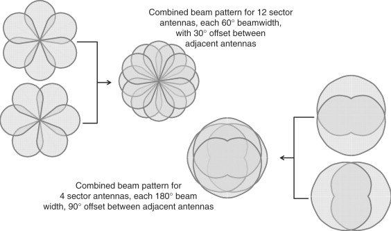
This type of device, with 16 access points operating 802.11a and g networks at an individual headline data rate of 54 Mbps, offers a total wireless LAN capacity of 864 Mbps. The increased gain of the sector antennas also means that the operating range of an access point array can be double or more the range of a single access point with an omnidirectional antenna.
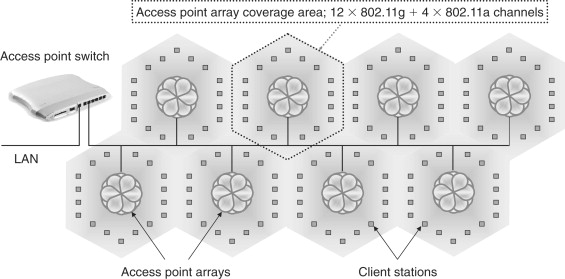
For high capacity coverage over a larger operating area, multiple access point arrays, controlled by a second tier of WLAN controllers would create a tree topology, as shown in Figure 3.13, with multi-gigabit total WLAN capacity.
Figure 3.13. WLAN tree topology employing access point arrays
3.3.6. Miscellaneous Wireless LAN Hardware
3.3.6.1. Wireless Network Bridging
Wireless bridge components that provide point-to-point WLAN or WMAN links are available from a number of manufacturers, packaged in weather proof enclosures for outdoor use (Figure 3.14). The D-Link DWL 1800 is one example which bundles a 16 dBi flat panel antenna with a 2.4 GHz radio providing a transmit power of 24 dBm (under FCC) or 14 dBm (under ETSI regulations), to deliver a range of 25 km under FCC or 10 km under ETSI.
Figure 3.14. Outdoor wireless bridges
(courtesy of D-Link (Europe) Ltd. and Linksys (a division of Cisco Systems Inc.))
Many simple wireless LAN access points also support network bridging, or can be upgraded with a firmware upgrade to provide this capability. Configuring these devices simply involves entering the MAC address of the other endpoint into each station’s access control list, so that each station only decodes packets transmitted by the other endpoint of the bridge.
3.3.6.2. Wireless Printer Servers
A wireless printer server allows a printer to be flexibly shared among a group of users in the home or office without the need for the printer to be hosted by one computer or to be connected to a wired network.
Typically, as well as wired Ethernet and wireless LAN interfaces, this device may include one or more different types of printer connections, such as USB or parallel printer ports, as well as multiple ports to enable multiple printers to be connected—such as a high-speed black and white laser and a separate color printer.
A printer server for home or small office wireless networking may also be bundled with a 4-port switch to enable other wired network devices to share the printer and use the wireless station as a bridge to other devices on the wireless network. Figure 3.15 shows a range of wireless printer servers.
Figure 3.15. Wireless printer servers

(courtesy of Belkin Corporation, D-Link (Europe) Ltd. and Links (a division of Cisco Systems Inc.))
3.3.7. Wireless LAN Antennas
3.3.7.1. Traditional Fixed Gain Antennas
Antennas for 802.11b and 11g networks, operating in the 2.4 GHz ISM band, are available to achieve a variety of coverage patterns. The key features that dictate the choice of antenna for a particular application are gain, measured in dBi, and angular beamwidth, measured in degrees.
The most common WLAN antenna, standard in all NICs and in most access points, is the omnidirectional antenna, which has a gain in the range from 0 to 7 dBi and a beamwidth, perpendicular to the antenna axis, of a full 360°. A range of WLAN antennas is shown in Figure 3.16 and Table 3.5 summarizes typical parameters. For sector antennas with a given horizontal beamwidth, the trade-off for higher gain is a narrower vertical beamwidth, which will result in a smaller coverage area at a given distance and will require more precise alignment.
Figure 3.16. Wireless LAN antenna types
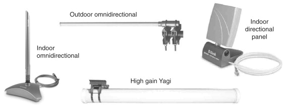
(courtesy of D-Link (Europe) Ltd.)
Table 3.5. Typical wireless LAN antenna parameters for 2.4 GHz operation
| Antenna type | Sub-type | Beamwidth (Degrees) | Gain (dBi) |
|---|---|---|---|
| Omnidirectional | 360 | 0–15 | |
| Patch/Panel | 15–75 | 8–20 | |
| Sector | 180 | 8–15 | |
| 120 | 9–20 | ||
| 90 | 9–20 | ||
| 60 | 10–17 | ||
| Directional | Yagi | 10–30 | 8–20 |
| Parabolic reflector | 5–25 | 14–30 |
A further important feature of an antenna is its polarization, which refers to the orientation of the electric field in the electromagnetic wave emitted by the antenna. Most common antennas, including all those listed in Table 3.5, produce linearly polarized waves, with the electrical field oriented either vertically or horizontally—hence vertical or horizontal polarization. WLAN antennas that produce circular polarization are also available (helical antennas) but are less common.
It is important that the polarizations of transmitting and receiving antennas are matched, since a vertical polarized receiving antenna will be unable to receive a signal transmitted by a horizontally polarized transmitting antenna, and vice versa. It is equally important for antennas to be correctly mounted, as rotating an antenna 90° about the direction of propagation will change its polarization by the same angle (e.g., from horizontal to vertical).
Although WLAN operation in the 5-GHz band has developed more recently than in the 2.4-GHz band, a similar selection of antennas is available for the higher-frequency band. A variety of dual band omnidirectional and patch antennas are also available to operate in both WLAN bands.
3.3.7.2. Smart Antennas
The data throughput of a wireless network that uses a traditional antenna of the type described above is limited because only one network node at a time can use the medium to transmit a data packet. Smart antennas aim to overcome this limitation by allowing multiple nodes to transmit simultaneously, significantly increasing network throughput. There are two varieties of smart antenna—switched beam and adaptive array.
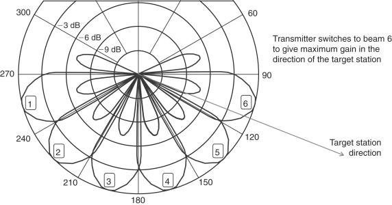
A switched beam antenna consists of an array of antenna elements each having a predefined beam pattern with a narrow main lobe and small side-lobes (Figure 3.17). Switching between beams allows one array element to be selected that provides the best gain in the direction of a target node, or the lowest gain towards an interfering source.
Figure 3.17. Beam pattern of a six element switched beam array
The simplest form of switched beam antenna is the pair of diversity receiver antennas often implemented in wireless LAN access points to reduce multipath effects in indoor environments. The receiver senses which of the two antennas is able to provide the highest signal strength and switches to that antenna.
Adaptive beams or beam-forming antennas consist of two or more antenna elements in an array and a so-called beam-forming algorithm, which assigns a specific gain and phase shift to the signal sent to or received from each antenna element. The result is an adjustable radiation pattern that can be used to steer the main lobe of the beam in the direction of the desired maximum gain (Figure 3.18).
Figure 3.18. Phase shift between two antennas resulting in a directed beam

As well as focusing its beam pattern towards a particular node, the adaptive beam antenna can also place a “null” or zero gain point in the direction of a source of interference. Because the gain and phase shift applied to individual array elements is under real-time software control (Figure 3.19), the antenna can dynamically adjust its beam pattern to compensate for multipath and other sources of interference and noise. Like adaptive beam arrays, multi-input multi-output or MIMO, radio also uses multiple antennas to increase network capacity. The key difference between these two techniques is that MIMO radio exploits multipath propagation between a single transmitter and receiver, while adaptive beam arrays use multiple antennas to focus a single spatial channel. Some other differences are described in Table 3.6.
Figure 3.19. Adaptive beam antenna
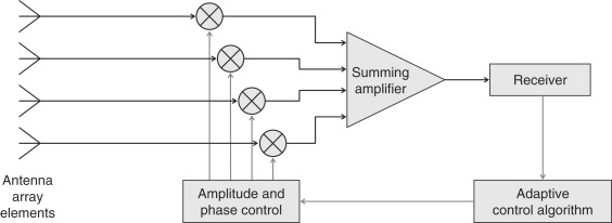
Table 3.6. Adaptive beam arrays and MIMO radio compared
| Adaptive beam array | MIMO radio | |
|---|---|---|
| Objective | Focus the propagation pattern along a single desired spatial direction, to allow multiple access, reduce interference or increase range. | Exploit multipath propagation to increase data capacity by multiplexing data streams over several spatial channels. |
| Antenna configuration | Two or more antenna elements at Tx and/or Rx. Tx and Rx configurations are independent. | Typically 2×2 or 4×4 (Tx×Rx). Tx and Rx are linked by the digital signal processing algorithm. |
| Spatial diversity | Single spatial channel focused between transmitter and receiver. | Multiple spatial channels, exploiting multipath propagation. |
| Data multiplexing | Single bit stream encoded to all transmit antennas. | Data stream multiplexed over spatial channels. |
| Signal processing | Simple phase and gain modification for each antenna. | Complex processing algorithm to decode signals over multiple spatial channels. |
| Application example | 3rd generation WLAN access points—Section 3.3 | PHY layer for the 802.11n standard |
Also under development is a new type of switched beam wireless LAN antenna called a plasma antenna, which uses a solid-state plasma (an ionized region in a silicon layer) as a reflector to focus and direct the emitted RF beam. A plasma antenna will be able to switch a medium gain (10–15 dBi) beam with approximately 10° beamwidth to 1 of 36 directions within a full 360° coverage, with a switching time that is less than the gap between transmitted frames.
3.4. Wireless PAN Devices
3.4.1. Wireless PAN Hardware Devices
In this section the wide range of PAN technologies will be described, from Bluetooth, which is most commonly identified with personal area networking, to ZigBee, a technology primarily aimed at networking home and industrial control devices.
3.4.1.1. Bluetooth Devices
with high powered (Class 1) Bluetooth radios, which can equal the range of Wi-Fi devices, the boundary between personal and local area networking is blurred and, within the limitations of achievable data rates, most of the WLAN devices described in Section 3.3 could equally well be built using Bluetooth technology.
The most common types of Bluetooth devices and some of their key features are summarized in Table 3.7 and shown in Figure 3.20.
Table 3.7. Bluetooth devices and features
| Bluetooth device | Key features |
|---|---|
| Mobile phone | Interface with a Bluetooth hands-free headset.Connect to PDA or PC to transfer or back-up files. Exchange contact details (business cards), calendar entries, photos, etc. with other Bluetooth devices. |
| PDA | Connect to PC to transfer or back-up files.Connect to the Internet via a Bluetooth access point.Exchange contact details (business cards), calendar entries, photos, etc. with other Bluetooth devices. |
| Headset or headphones | Hands-free mobile telephony.Audio streaming from PC, TV, MP3 player or hi-fi system. |
| Audio transceiver | Audio streaming from a PC or hi-fi system to Bluetooth headphones. |
| Access point | Extend a LAN to include Bluetooth enabled devices.Internet connectivity for Bluetooth devices. |
| Bluetooth adapters | Bluetooth enable a range of devices, such as laptops or PDAs.As for WLAN NICS, they are available in a range of form factors, with USB dongles being the most popular.Serial adapter for plug-and-play connectivity to any serial RS-232 device. |
| Print adapter | Print files or photos from Bluetooth enabled device. |
| PC input devices | Wireless connectivity to a PC mouse or keyboard. |
| GPS receiver | Provide satellite navigation capabilities to Bluetooth-enabled devices loaded with required navigation software. |
| Dial-up modem | Provide wireless connectivity from a PC to a dial-up modem. |
Figure 3.20. A variety of Bluetooth devices
(courtesy of Belkin Corporation, D-Link (Europe) Ltd., Linksys (a division of Cisco Systems Inc.) and Zoom Technologies, Inc.)
As developing wireless PAN technologies such as wireless USB mature, a comparable range of devices will be developed to support these networks. Novel capabilities inherent in these new technologies will also result in new device types offering new services, an example being the capability of the multi-band OFDM radio to spatially locate a wireless USB station, offering the potential for devices that rely on location based services.
3.4.1.2. ZigBee Devices
ZigBee is a low data rate, very low power, wireless networking technology that initially has focused on home automation but is likely to find a wide range of applications, including a low cost replacement for Bluetooth in applications that do not require higher data rates.
The key features of a range of currently available and expected ZigBee devices is summarized in Table 3.8, and some of these devices are shown in Figure 3.21.
Table 3.8. ZigBee devices and features
| ZigBee device | Key features |
|---|---|
| PC input devices | Wireless connectivity to a PC mouse or keyboard. |
| Automation devices | Wireless control devices for home and industrial automation functions such as heating, lighting and security. |
| Wireless remote control | Replacing Ir remote for TV etc., and eliminating the line-of-sight and alignment restriction. |
| Sensor modem | Provides a wireless networking interface for a number of existing current loop sensors for home or industrial automation. |
| Ethernet gateway | A ZigBee network coordinator that enables command of ZigBee end devices or routers from an Ethernet network. |
Figure 3.21. A variety of ZigBee devices
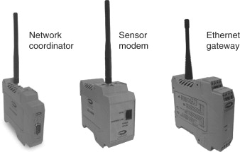
(courtesy of Cirronet Inc.)
3.4.2. Wireless PAN Antennas
In practice, since PAN operating range is generally under ten meters, Bluetooth and other PAN devices will typically use simple integrated omnidirectional antennas. However, for PANs such as Bluetooth that share the 2.4-GHz ISM radio band with 802.11b/g WLANs, the wide range of external WLAN antennas described above are also available to enable PAN devices to be operated with extended range.
3.5. Wireless MAN Devices
While wireless LANs and PANs present a wide diversity of topologies and device types, to date wireless MAN devices have serviced only fixed point-to-point and point to multi-point topologies, requiring in essence only two device types, the base station and the client station.
However, following the ratification of the 802.16e standard (also designated 802.16-2005), broadband Internet access will soon be widely available to mobile devices and a range of new mobile wireless MAN devices is emerging, driving the convergence of mobile phones and PDAs.
3.5.1. Fixed Wireless MAN Devices
Wireless networking devices for fixed wireless MAN applications, essentially for last mile broadband Internet access, fall into two categories—base station equipment and customer premises equipment (CPE).
Some examples of base station equipment to support wireless MANs of differing scales are shown in Figure 3.22. The macro scale base station shown can potentially support thousands of subscribers in dense metropolitan area deployments, while the micro scale equipment is designed to support lower user numbers in sparse rural areas. Some of the types and key features of base station and CPE hardware are summarized in Table 3.9.
Figure 3.22. Micro and macro WMAN base station equipment

(courtesy of Aperto Networks Inc.)
Table 3.9. Wireless MAN devices and features
| WMAN device | Typical features |
|---|---|
| Basic self installed indoor CPE | Basic WMAN connectivity to a customer PC or network.Multiple diversity or adaptive array antennas to improve non line-of-sight reception. |
| Outdoor CPE | External antenna and radio.Provides higher antenna gain and longer range. |
| Base station equipment | Modular and scalable construction.Macro and micro configurations for dense metropolitan or sparse rural installations.Flexible RF channel usage, from one channel over multiple antenna sectors to multiple channels per antenna sector. |
| Integrated network gateway | MAN interface with network gateway functions (Routing, NAT and firewall capabilities).Optionally with integrated wireless LAN access point.Integrated CPU to support additional WISP services such as VoIP telephony. |
Figure 3.23 shows a variety of different wireless MAN CPE equipment.
Figure 3.23. Fixed wireless MAN CPE equipment

(courtesy of Aperto Networks Inc.)
3.5.2. Fixed Wireless MAN Antennas
Antennas for fixed wireless MAN applications similarly divide into base station and CPE. The general types of antennas summarized earlier in Table 3.5 for LANs are equally applicable to MAN installations, with appropriate housings for outdoor service and mountings designed for wind and ice loading. The factors that determine the choice of antenna are summarized in Table 3.10.
Table 3.10. Factors determining wireless MAN antenna choice
| Location | Antenna type | Application |
|---|---|---|
| CPE | Omnidirectional | Low gain requirement—for subscribers located close to the base station. |
| Patch | Intermediate gain—mid range equipment should be applicable to most subscribers. | |
| Directional (Yagi or parabolic reflector) | High gain, high cost equipment to maximize data rate at the edge of the operating area. | |
| Base station | Sector, intermediate gain | Wide area coverage close to the base station. Wider vertical beamwidth required to provide coverage close to the base station. |
| Sector, high gain | Wide area coverage at a distance from the base station. High gain adds range with narrower vertical beamwidth. | |
| Directional | High gain antenna for point-to-point applications, such as backhaul, bridging between base stations, etc. |
Depending on its elevation relative to the target area, a base station may comprise two sets of sector antennas as illustrated in Figure 3.24. A set of intermediate gain antennas, with higher vertical beamwidth, provide coverage over short-to-medium distances, with a second set of high-gain, low vertical beamwidth antennas providing coverage at longer range.
Figure 3.24. WMAN base station sector antenna configuration

3.5.3. Mobile Wireless MAN Devices
The first implementation of mobile wireless MAN services and devices, delivering broadband Internet access to the user on the move, has been in the South Korean market, driven by the rapid development of the WiBro standard (a sub-set of 802.16e). Commercial uptake has also been speeded by the use of licensed spectrum, and the granting in 2005 of operating licenses to three telecom companies.
The form factor for devices to deliver mobile Internet services reflects the need to combine telephony and PDA capabilities—a larger screen and QWERTY input to overcome the limitations experienced with WAP phones. Figure 3.25 shows two early WiBro phones developed by Samsung.
Figure 3.25. Wireless MAN enabled phones

(courtesy of Samsung Electronics)