
Chapter 21. Implementing Advanced Wireless Security
21.1. Introduction
The practical security measures discussed in Chapter 20, “Basic Wireless Network Security,” are, as a general rule, sufficient for most home wireless users. Corporate users, however, should not rely on basic security measures alone to protect their wireless networks. In this chapter, we discuss some of the more advanced ways to reduce the risk of your wireless network being compromised.
In this chapter, you will also learn about different methods of secondary authentication such as Virtual Private Networks (VPNs) and Remote Authentication and Dial-In User Service (RADIUS). A secondary authentication mechanism requires that, in addition to association with a wireless access point, a user must authenticate (that is, log in) using some other means. But, first, we will look at the replacement for Wired Equivalent Privacy (WEP): Wi-Fi Protected Access (WPA).
21.2. Implementing Wi-Fi Protected Access (WPA)
Wi-Fi Protected Access (WPA) is designed to provide wireless users with an encryption mechanism that is not susceptible to the vulnerabilities of Wired Equivalent Privacy (WEP). Most 802.11g access points either ship with the option to use WPA or a firmware upgrade can be downloaded from the access point manufacturer.
Before enabling WPA, you should ensure that your wireless card has WPA drivers. As with access points, you often need to update the card’s drivers, firmware, or both in order to take advantage of WPA. This section details how to set up WPA encryption on two access points: the D-Link DI-624 and the Linksys WRV54G. You will also learn how to configure your wireless client to use WPA.
21.2.1. Configuring the D-Link DI-624 AirPlus 2.4 GHz Xtreme G Wireless Router with 4-Port Switch
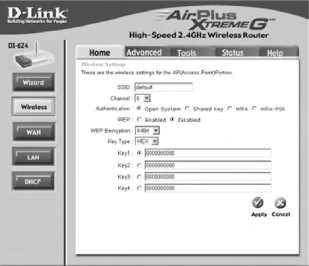
The D-Link DI-624 ships with WPA capability. This means that no firmware upgrade is necessary and you can start using WPA as soon as the DI-624 comes out of the box. First, you need to log into the DI-624 from a wired connection. Then, point your browser to 192.168.0.1 and supply the username admin with a blank password when prompted. This opens the initial configuration screen, as seen in Figure 21.1.
Figure 21.1. The DI-624 initial configuration screen

Next, click the Wireless button on the left to open the wireless configuration options window, as shown in Figure 21.2.
Figure 21.2. The Wireless Configuration Options window
Next, choose either the WPA or WPA-PSK Authentication options. The WPA option requires a RADIUS server, whereas WPA-PSK (Pre Shared Key) sets a passphrase that must also be entered in the client WPA configuration settings. See Figures 21.3 and 21.4.
Damage & Defense
Known WPA-PSK Vulnerability
WPA-PSK utilizes a 256-bit pre-shared key or a passphrase that can vary in length from 8 to 63 bytes. Short passphrase-based keys (less than 20 bytes) are vulnerable to the offline dictionary attack. The pre-shared key that is used to set up the WPA encryption can be captured during the initial communication between the access point and the client card. Once an attacker has captured the pre-shared key, he can use that to essentially “guess” the WPA key using the same concepts used in any password dictionary attack. In theory, this type of dictionary attack takes less time and effort than attacking WER Choosing a passphrase that is more than 20 bytes mitigates this vulnerability.
Figure 21.3. The WPA configuration screen
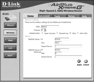
Figure 21.4. The WPA-PSK configuration screen
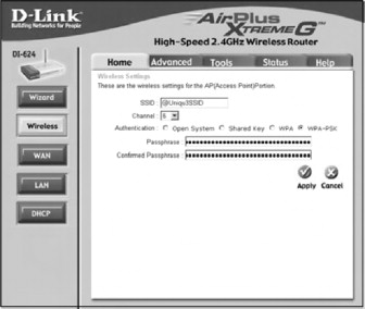
Enter either your RADIUS server information and Shared Secret for WPA or a strong passphrase that is more than 20 bytes long, and then click Apply to save your settings and enable WPA.
21.2.2. Configuring the Linksys WRV54G VPN Broadband Router
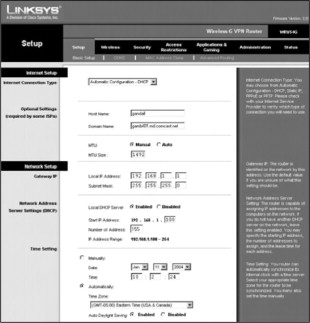
The Linksys WRV54G VPN-Broadband Router may require a firmware upgrade to allow WPA capability. Firmware version 2.10 or later is required for WPA functionality on the WR.V54G. To enable WPA, you need to log in to the WRV54G, as shown in Figure 21.5. Point your browser to the IP address of the WRV54G. By default, this is 192.168.1.1. There is no username required and the default password is admin.
Figure 21.5. The Linksys WRV54G initial configuration screen
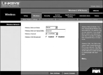
Next, click the Wireless tab to display the Wireless Network Settings, as seen in Figure 21.6.
Figure 21.6. The wireless networks settings screen
Then, choose the Wireless Security option to display the Wireless Security settings, as seen in Figure 21.7.
Figure 21.7. The wireless security settings
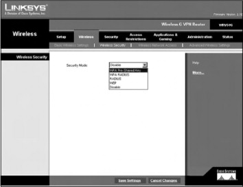
The Security Mode drop-down box displays the four modes of security available on the WRV54G:
- WPA Pre-Shared Key
- WPA Radius
- RADIUS
- WEP
WPA RADIUS requires a RADIUS server, as shown in Figure 21.8. WPA Pre-Shared Key (Figure 21.9) allows you to enter a strong pre-shared key. All wireless clients must also be configured to use the WPA pre-shared key in order to authenticate to the wireless network.
Figure 21.8. The WPA RADIUS settings

Figure 21.9. The WPA Pre-Shared Key settings

Finally, enter the RADIUS server IP address and shared secret, or the pre-shared key and choose Save Settings to enable WPA support.
21.2.3. Configuring Windows XP Wireless Clients for WPA
In order to take advantage of WPA, you must configure your wireless client. To allow Windows XP to work with WPA you must first install the Microsoft Update for Microsoft Windows XP (KB826942). This patch enables WPA compatibility in Windows XP. After installing KB826942, double-click the Wireless Network Connection icon on the toolbar. This opens the Wireless Network Connection Properties window, as seen in Figure 21.10. If you have a profile for your access point already set up, select it and click Properties. Otherwise, select Add under the Preferred Networks. The connection properties window will open.
Figure 21.10. The Connection Properties window

Next, enter the SSID for your access point in the Network Name textbox, as shown in Figure 21.11. Then, choose the type of encryption you configured your access point to use—WPA or WPA-PSK—and then the encryption standard: WEP, Temporal Key Integrity Protocol (TKIP), or Advanced Encryption Standard (AES). Finally, input the pre-shared key configured on your access point into the Network key and Confirm network key textboxes.
Figure 21.11. WPA Client Settings

Your client setup is now complete and you can utilize your wireless network with WPA security.
Notes from the Underground
WPA In Linux with Linuxant DriverLoader
In order to utilize WPA, you must have drivers for your wireless card that support it. Most 802.11g cards either have a WPA capable driver when they are purchased, or one can be downloaded. The problem is that these drivers are for Windows. Linux users have not been able to enjoy the benefits of WPA because there are very few card manufacturers that have released WPA drivers for Linux. Linuxant has offered a solution to this problem for many cards: DriverLoader.
DriverLoader allows you to use the Windows driver for cards based on the Atheros, Broadcom, Cisco, Intel Centrino, Prism, Realtek, and Texas Instruments chipsets in Linux. DriverLoader also supports WPA. It is available for a free trial from the Linuxant web site (www.linuxant.com/driverloader/) and a permanent license can be purchased for $19.95 at the time of this writing.
21.3. Implementing a Wireless Gateway with Reef Edge Dolphin
The first solution we’ll examine is freeware. Free is always a good thing, especially in the IT industry! Reef Edge (www.reefedge.com) produces several commercial products for use in securing wireless networks, including Connect Manager. Dolphin is a somewhat scaled-down version of Connect Manager that still provides the same basic features, but is flee. If you need to add an unlimited number of users, or add new user groups, you should investigate Connect Manager. The Dolphin FAQ (http://techzone.reefedge.com/dolphin/index/faq.page) provides more information on the limitations of Dolphin in comparison to Connect Manager.
Dolphin runs a hardened version of Linux and, once installed, acts almost the same as any other network appliance. The chief difference is that console and Telnet logins are not supported; all access is via the Secure Socket Layer (SSL) secured Web interface. An aging piece of Intel 586 hardware can be quickly and easily transformed into a secure wireless gateway, providing access control from the wireless network to the wired network, which we demonstrate in this chapter. Dolphin is a noncommercial product and not to be used in large implementations, but it does provide an ideal (and affordable) solution for Small Office/Home Office (SOHO) applications and serves as an excellent test bed for administrators who want to get their feet wet with wireless without opening their networks to security breaches. If you find that Dolphin is to your liking, you might want to consider contacting Reef Edge to purchase Connect Manager or an edge controller. An edge controller is a second, or satellite, machine that can be set up to support your wireless network. You will be able to easily move up to these solutions with the knowledge you gain by configuring and using Dolphin.
Note
SSL was developed in 1996 by Netscape Communications to enable secure transmission of information over the Internet between the client end (Web browsers) and Web servers. SSL operates between the application and transport layers and requires no actions on the part of the user. It is not a transparent protocol that can be used with any application layer protocol; instead, it works only with those application layer protocols for which it has been explicitly implemented. Common transport layer protocols that make use of SSL include: HyperText Transfer Protocol (HTTP), Simple Mail Transfer Protocol (SMTP), and Network News Transfer Protocol (NNTP).
SSL provides the three tenants of Public Key Infrastructure (PKI) security to users:
- Authentication Ensures that the message being received is from the individual claiming to send it.
- Confidentiality Ensures that the message cannot be read by anyone other than the intended recipient.
- Integrity Ensures that the message is authentic and has not been altered in any way since leaving the sender.
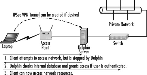
Dolphin provides some robust features that are typically found in very expensive hardware-based solutions, including secure authentication, IPSec security, and session roaming across subnets. Users authenticate to the Dolphin server over the WLAN using SSL-secured communications and then are granted access to the wired network. Dolphin supports two groups, users and guests, and you can control the access and quality of service of each group as follows:
- Users Trusted users who can use IPSec to secure their connection and access all resources.
- Guests Unknown users who are not allowed to use IPSec to secure their communications and have access control restrictions in place.
Finally, Dolphin supports encrypted wireless network usage through IPSec tunnels. Through the creation of IPSec VPN tunnels, users can pass data with a higher level of security (encryption) than WEP provides.
To begin working with Dolphin, you need to register for the Reef Edge TechZone at http://techzone.reefedge.com. Once this is done, you will be able to download the CD-ROM ISO image and bootable diskette image files from the Reef Edge download page. The server that you are using for Dolphin must meet the following minimum specifications:
- Pentium CPU (586) or later
- Pentium CPU (586) or later
- 64 MB IDE hard drive as the first boot IDE device
- IDE CD-ROM
- Diskette drive if the CD-ROM drive being used is not E1Torrito compliant (see www.area51partners.com/ftles/eltorito.pdf for more information on this specification).
- Two Peripheral Component Interconnect (PCI) network adapters from the following list of compatible network adapters:
- 3Corn 3c59x family (not 3c905x)
- National Semiconductor 8390 family
- Intel EtherExpress 100
- NE2000/pci
- PCNet32
- Tulip family
The Dolphin implementation is depicted in Figure 21.12.
Figure 21.12. Dolphin provides gateway services for the wireless network
21.3.1. Installing Dolphin
Once you’ve gathered all the required items, you can begin installing Dolphin on your server. To do so, perform these steps:
Note
Although these are the default credentials to enter your Dolphin system, it is critical that you change them once you are done with the initial configuration. After you have created your first user account, Dolphin will delete the temp account for you automatically to ensure that no one compromises the server or gains unauthorized network access.
Note
If you don’t have a crossover cable, you can use a switch or hub and two standard straight-through cables. Simply connect the Dolphin server to the management station through the switch or hub. Ensure that you are using the uplink port on the switch or hub and, if required by your hardware, ensure that the uplink port is selected for uplink via regular use. Also make sure that you are on the right network segment with correct IP addressing configured.
- Create the CD-ROM from the ISO image. If required, create the bootable diskette from the floppy disk image.
- Connect a keyboard, mouse, and monitor to the Dolphin server.
- Power on the Dolphin server and place the Dolphin CD-ROM in the CD-ROM drive. If your computer is not capable of booting directly from the CD, you will also need to use the boot diskette.
- Select OK when prompted to start the installation.
- Accept the EULA when prompted.
- Acknowledge, when prompted, that installing Dolphin will erase the contents of the first physical disk.
- Restart the Dolphin server as prompted after the installation has been completed. After the restart, you will see a long series
of dots followed by this message:
- System Ready. IP address: 192.168.0.1/255.255.255.0.
- This value represents the wired side of the Dolphin server and can be changed later if you desire by completing the steps in the “Configuring Dolphin” section of this chapter.
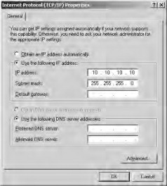
- Determine which network adapter is which on the Dolphin server. Configure the network adapter on your management station (depicted
in Figure 21.15) with the IP address of 10.10.10.10 and a subnet mask of 255.255.255.0, as shown in Figure 21.13.
Figure 21.15. Making the Dolphin connections
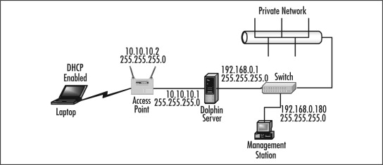
Figure 21.13. Configuring the network adapter
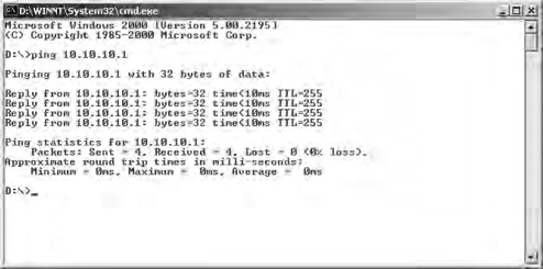
- Connect directly using a crossover cable between your management station and one of the network adapters on the Dolphin server,
ping the Dolphin server with an IP address of 10.10.10.1. If you receive an echo reply, as shown in Figure 21.14, you have located the wireless side of the Dolphin server. If you don’t get an echo reply, make the connection to the other
network adapter on the Dolphin server. Attempt to ping the other network adapter on the Dolphin server with the IP address
of 10.10.10.1 to verify connectivity. The wired side of the Dolphin server intially has the IP address of 192.168.0.1 with
a subnet mask of 255.255.255.0, as mentioned in Step 7. You can, however, change the IP addresses and subnet masks of both the wireless and wired side of the Dolphin server if you so desire, as discussed in the
next section, “Configuring Dolphin.”
Figure 21.14. Finding the wireless side of the Dolphin server
- Configure your management station with an IP address in the 192.168.0.x range, such as 192.168.0.180, and connect it to the wired side (192.168.0.1) of the Dolphin server, preferably through a switch, but you can use a crossover cable to make a direct connection.
- Configure your wireless client for Dynamic Host Configuration Protocol (DHCP) so that it can receive an IP address and DNS server information from the Dolphin server. (You can change the DHCP values passed out later in this procedure.)
- Connect the AP to the wireless side of the Dolphin server (10.10.10.1). Ensure that the AP and the wireless side of the Dolphin server are configured correctly, with IP addresses on the same subnet. You should now have an arrangement like the one shown in Figure 21.15.
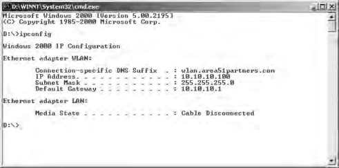
- Force the wireless client to renew its DHCP lease and check to see that it looks something like the one shown in Figure 21.16.
Figure 21.16. Verifying the DHCP lease
- Ping the wireless side of the Dolphin server, from the wireless client, at 10.10.10.1 to verify connectivity.
- Ping the wireless side of the Dolphin server again, from the wireless client, using the DNS name mobile.domain.
- Attempt to access resources on the wired network from the wireless client. Acknowledge the SSL connection if prompted to do
so (although you won’t actually see any SSL-secured pages until you attempt to log in at the next step). If you see the Web page in Figure 21.17, congratulate yourself—your Dolphin installation is operating properly!
Figure 21.17. Connecting to the Dolphin server

- Log in from the page shown in Figure 21.18 using the username temp and the password temp. If login is successful, you will see the page shown in Figure 21.19. Notice that the IPSec key shown at the bottom of the page is actually your shared key that you would use to create IPSec
connections.
Figure 21.18. Logging into the Dolphin web page

Figure 21.19. Login is successful

- Log in to the Dolphin Web management interface by entering https://mobile.domain/admininto your browser. You will be prompted to log in, as shown in Figure 21.20.
Figure 21.20. Logging in to the administrative interface

21.3.2. Configuring Dolphin
Your Dolphin server is now installed and operable on your wireless network. You now need to perform some configuration and management tasks before your server is ready to be placed into production. You need to add users to the Dolphin database who will be allowed to gain access to the wireless network. (Dolphin does not support RADIUS and thus must use a local user database.) In addition, you might want to change the IP addresses and subnets assigned to the Dolphin server network adapters. The following steps walk you through the process of configuring some of these options:
- Log in to the Dolphin server by completing Steps 17–18 of the previous procedure.
- Click the Wired LAN link from the menu on the left side of the window. This provides you with the capability to change the wired-side properties,
as shown in Figure 21.21. In most cases, you’ll need to change the wired-side IP address from the default configuration of 192.168.0.1 because this
is typically reserved for use by the default gateway. Be sure to enter the default gateway and DNS server IP addresses as
well as to enable wireless network clients to access network resources. After making your changes, click the Save button. (Note that you will have to restart the Dolphin server to commit the changes to the running configuration. You can,
however, make all your changes and then restart the server.)
Figure 21.21. Changing the wired-side network properties

- Click the Wireless LAN link to configure the wireless-side properties, as shown in Figure 21.22. You can change all these properties as you see fit. By default, the Dolphin server is configured with the domain name reefedge.com
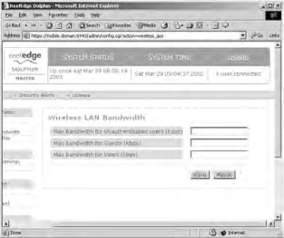
and DHCP address range of 10.10.10.10–10.10.10.253. After making your changes, click the Save button. If you want to configure the quality of service that wireless clients receive, click the Wireless LAN Bandwidth link to configure your values, as shown in Figure 21.23. After making your changes, click the Save button.
Figure 21.22. Changing the wireless-side network properties
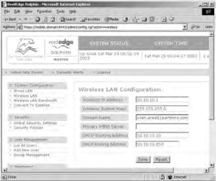
Figure 21.23. Dolphin provides quality of service controls for wireless clients
- Create a list of authorized users for Dolphin—that is, a listing of users who can authenticate to Dolphin and then be granted
wireless network access. Click the Add New User link to open the User Management page shown in Figure 21.24. Note that you can only choose between the users group and the guests group—Dolphin does not support creating custom groups
(a limitation due to its freeware status). After supplying the required information, click Save. After creating your first Dolphin user, the “temp” account will be deleted for security reasons. If you want to configure
additional security policies, click the Security Policies link to open the Security Policies For User Groups page, shown in Figure 21.25. This page allows you to configure the equivalent of a firewall rule set for your Dolphin server.
Figure 21.24. Creating users for the Dolphin Database
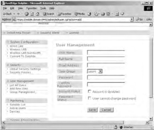
Figure 21.25. Creating or modifying security policies

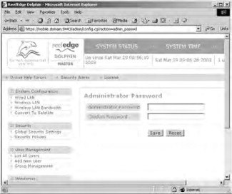
- Change the administrative password to restart your Dolphin server. To do this, scroll the page all the way to the bottom and
click the Admin Password link. Click Save after making your change (see Figure 21.26).
Figure 21.26. Changing the administrator password
- Restart your Dolphin server. After Dolphin has completed loading, you will see the familiar series of dots, this time followed by the new wired-side IP address that you have configured.
21.3.3. Improving the User Experience
Should you not want authorized users to need to use the Web interface to Dolphin to authenticate, you can equip them with a small utility that is available from Reef Edge, and can be used to perform regular and IPSec-secured logins/logouts. The process to install and use this utility is outlined here:
Tools and Traps
Using Enterprise Wireless Gateways
Don’t think of Dolphin as a full-featured Enterprise Wireless Gateway (EWG). However, you should consider it a wireless gateway. For a full featured EWG, you might want to consider one of the more capable and robust (and more expensive) solutions offered from one of the following vendors:
- Bluesocket www.bluesocket.com
- Columbitech www.columbitech.com
- Reef Edge www.reefedge.com
- Sputnik www.sputnik.com
- Vernier Networks www.verniernetworks.com
- Viator Networks www.viatornetworks.com
These solutions offer the same features as Dolphin—authentication and VPN support—but they also provide many other options, such as RADIUS server support, hot failover support, and multiple protocol support (such as WAP, 3G, and 802.11). The EWG market is still in a great deal of flux as vendors try to refine their products. That does not mean, however, that you cannot create very secure solutions using today’s technology. A word of caution, though: You should expect to find bugs and other errors with most of these solutions because the technology is still so new. Caveat emptor.
- Download the Active TCL package from Active State at www.activestate.com/Products/Download/Download.plex?id=ActiveTCL and install it onto your wireless client computer.
- Download the TCL TLS 1.4 package from Reef Edge’s download page. Create a folder called tlsl.4 in the lib directory of the Active TCL installation path and extract the contents of the TLS 1.4 archive into this folder.
- Download the dolphin_status.tcl file, also located at the Reef Edge download page.
- Place the dolphin_status.tcl file in a convenient location on the client computer. Once Active TCL has been installed, the dolphin_status.tcl file will act as an executable and can be double-clicked to open.
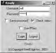
- Execute the dolphin_status.tcl file to get the login prompt shown in Figure 21.27. You have the option of creating an IPSec tunnel at this time as well. The tcl file will create a configuration ftle named
dolphin in the same directory it is located in.
Figure 21.27. Using the Dolphin_status.tcl file to log in
21.3.4. Dolphin Review
As you’ve seen in this chapter, the Dolphin product provides a very inexpensive solution for small wireless environments. It is very lightweight and has mammal hardware requirements; you most likely have an old PC stuffed in a storage room that could be turned into a dedicated wireless gateway by installing the Dolphin application on it.
On the up side, Dolphin is easy to use and configure, is inexpensive, and provides a relatively good amount of security for smaller organizations. In addition, Dolphin supports the creation of IPSec-secured VPN tunnels between the wireless clients and the Dolphin server. On the down side, Dolphin is limited in the number of users it can support as well as the number of groups you can create to classify users. Dolphin also does not provide for the use of an external RADIUS server. These limitations, however, are clearly stated by Reef Edge because Dolphin is not intended for commercial usage. If you have a small home or office wireless network that needs to be secured by an access-granting device, Dolphin might be an ideal choice for you.
Now that we’ve spent some time looking at the freeware Dolphin product, let’s step up the discussion and examine some more robust (and more costly) solutions that you might implement to secure a larger wireless network necessitating control over user access in a larger enterprise environment.
21.4. Implementing a VPN on a Linksys WRV54G VPN Broadband Router
The Linksys WRV54G is an access point/router combination that Linksys designed for the small office, or home user that desires a higher level of security than WEP or WPA can provide. The W-RV54G offers all of the security features of other access points, but also provides the capability of setting up an IPSec VPN tunnel. A VPN tunnel allows two points to establish an encrypted session using a selected protocol. Other protocols can then be transmitted through this tunnel. A basic example of this is a Secure Shell (SSH) tunnel. A firewall can be configured to allow only SSH traffic (port 22) inbound. The client can then tunnel other traffic, such as HTTP (port 80) through the established SSH tunnel. This both encrypts the HTTP traffic, and removes the requirement to allow port 80 traffic through the firewall. Additionally, because some form of authentication (passphrase, key exchange, or both) is required to establish the initial SSH tunnel, additional user level access controls are in place.
This section describes the process of setting up an IPSec tunnel to utilize the VPN features on the WRKV54G. First, we discuss the steps that must be taken on Windows 2000 or XP clients to prepare for VPN access. Then, the configuration steps that are required on the WRKV54G are detailed.
21.4.1. Preparing Windows 2000 or XP Computers for Use with the WRV54G
There are four steps that you need to take to configure your Windows 2000 or XP computer to establish a VPN tunnel with the WRV54G.
- Create an IPSec policy.
- Build two filter lists.
- Establish the tunnel rules.
- Assign the IPSec policy to the computer.
21.4.1.1. Creating an IPSec Policy
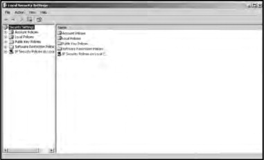
Click Start | Run and type secpol.msc in the Open textbox to open the Local Security Settings screen, as seen in Figure 21.28.
Figure 21.28. Local security settings
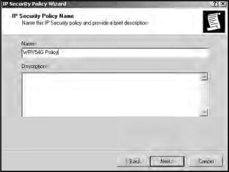
Right-click IP Security Policies on Local Computer and select Create IP Security Policy to open the IP Security Policy Wizard. Click Next on the IP Security Policy Wizard window.
Enter a name for your security policy in the Name textbox (as shown in Figure 21.29) and click Next.
Figure 21.29. Naming the local security policy
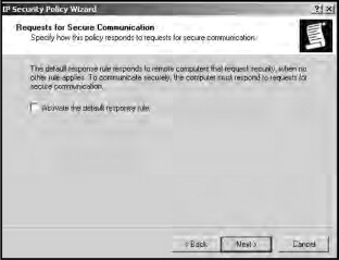
Remove the checkbox next to Activate the default response rule, as shown in Figure 21.30, and click Next.
Figure 21.30. Deactivate the default response rule
Finally, make sure that the Edit properties checkbox is selected, as shown in Figure 21.31, and click Finish.
Figure 21.31. Completing the local policy creation

21.4.1.2. Building Filter Lists
Selecting the Edit properties checkbox before finishing the IP Security Policy Wizard opens the Properties window for your new security policy (Figure 21.32).
Figure 21.32. The Policy Properties

Deselect the Use Add Wizard checkbox and click Add to open the New Rule Properties window. By default, this window opens on the IP Filter List tab. Click Add again to open the IP Filter List window. Enter a name for the filter, as shown in Figure 21.33. Deselect the Use Add Wizard checkbox and click Add.
Figure 21.33. The IP Filter List window

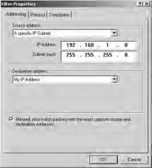
The Filter Properties window opens on the Addressing tab. Choose My IP Address in the Source Address field and A specific IP Subnet in the Destination Address field. In the IP Address field enter 192.168.1.0. This represents all addresses in the range 192.168.1.1–192.168.1.255. If you are using a different range, make sure to adjust this accordingly. Enter the Subnet Mask for your network in the Subnet Mask field (see Figure 21.34). By default, this is 255.255.255.0. Click the OK button to close this window.
Figure 21.34. The IP filter settings

Next, click OK in Windows XP or Close in Windows 2000. This filter is used for communication from your computer to the router.
You will then need to create a filter for communication from the router to your computer. In the New Rule Properties window, highlight the rule you just created, as shown in Figure 21.35, and click Add.
Figure 21.35. Creating the second filter

This opens the IP Filter List window. Enter a name for the new filter in the Name textbox and click Add. On the Addressing tab, choose A specific IP Subnet in the Source Address field. In the IP Address field, enter 192.168.1.0. This represents all addresses in the range 192.168.1.1–192.168.1.255. If you are using a different range, you will need to adjust this accordingly. Enter the subnet mask for your network in the Subnet Mask field. By default, this is 255.255.255.0. Choose My IP Address in the Destination Address field (Figure 21.36).
Figure 21.36. The Filter Properties window
Click the OK button to close this window. Next, click OK in Windows XP or Close in Windows 2000. This filter is used for communication from the router to your computer.
21.4.1.3. Establishing the Tunnel Rules
The rules that are employed by the tunnels must be set up in order to properly filter traffic through the VPN tunnel. First, select the tunnel you created for communication from your computer to the router and then click the Filter Action tab. Next, select the Require Security radio button and click Edit to open the Require Security Properties window, as shown in Figure 21.37.
Figure 21.37. The require security properties window

Ensure that the Negotiate security radio button is selected. Then, deselect Accept unsecured communication, but always respond using IPSec and select Session key perfect forward security (PFS), as shown in Figure 21.38
Figure 21.38. The security methods options

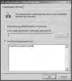
Click OK to return to the New Rule Properties window. Select the Authentication Methods tab and click Edit to open the Edit Authentication Method Properties window. Choose the Use this string (preshared key) radio button and enter the pre-shared key in the textbox (Figure 21.39). This can be a combination of up to 24 letters and numbers, but special characters are not allowed. Make sure that you remember this key as it will be used later when the router is configured.
Figure 21.39. Entering the pre-shared key
Next, click the OK button in Windows XP or the Close button in Windows 2000.
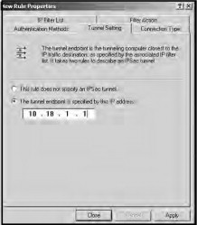
Select the Tunnel Setting tab on the New Rule Properties window. Select The tunnel endpoint is specified by this IP address and enter the external IP address of the WRV54G, as shown in Figure 21.40. This is the IP address your router uses to communicate with the Internet.
Figure 21.40. The Tunnel setting tab
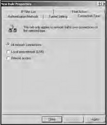
Next, click the Connection Type tab (as shown in Figure 21.41). Select All network connections if you want this rule to apply to both Internet and local area network (LAN) connections. Choose Local area network (LAN) if you want this tunnel to apply only to connections made from the local network. Choose Remote access if you want this rule to apply only to connections made from the Internet.
Figure 21.41. Select the connection type
After you have selected the type of network connections that the rule applies to, click Close.
Another filter rule must be created to allow communication from the router to your computer. To create this rule, repeat the steps outline in this section, but enter the IP address of your computer as the Tunnel Endpoint instead of the IP address of the router.
21.4.1.4. Assigning the Security Policy
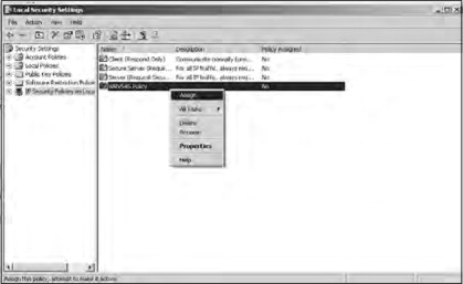
Finally, you must assign your new security policy to the local computer. In the Local Security Settings window, right-click the new policy that you have just created and select Assign, as shown in Figure 21.42.
Figure 21.42. Assigning the security policy
Your computer is now configured to communicate over a VPN tunnel.
21.4.2. Enabling the VPN on the Linksys WRV54G
Now that your computer is configured to communicate over an IPSec VPN tunnel, you must configure the WRV54G to communicate with your computer. Using your web browser, type the IP Address of the WRV54G into your address bar. This is 192.168.1.1, by default. You will be prompted for your username and password
From the setup screen, select Security | VPN to display the VPN settings, as seen in Figure 21.43.
Figure 21.43. The WRV54G VPN settings

Select the Enabled radio button for VPN Tunnel. Choose a name for this tunnel and enter it in the Tunnel Name textbox. Next, enter the IP address and netmask of the local network in the IP Address and Mask fields for the Local Secure Group. Use 192.168.1.0 to allow all IP addresses between 192.168.1.1–192.168.1.255.
Enter the IP address and netmask of the computer you just configured in the IP Address and Mask fields for the Remote Secure Group. Next, choose 3DES from the Encryption drop-down box. This requires the use of Triple Data Encryption Standard encryption. Choose SHA1 from the Authentication drop-down box.
Choose Auto(IKE) as the Key Exchange Method and select the Enabled radio button for PFS. This enables the use of Internet Key Exchange (IKE) and Perfect Forward Secrecy (PFS).
Finally, select the radio button next to Pre-Shared Key and enter the same pre-shared key you entered on your computer while setting it up.
Once you have entered these settings, your VPN setup screen should look similar to Figure 21.44.
Figure 21.44. The completed VPN settings.

Click Save Settings to save your settings and establish a VPN tunnel between the WRV54G and your computer.
21.5. Implementing RADIUS with Cisco LEAP
The use of RADIUS servers to authenticate network users is a longstanding practice. Using RADIUS server dynamic per-user, per-session WEP keys combined with IV randomization is a fairly new practice. Another new addition is Cisco’s proprietary offering (now being used by many third-party vendors), Lightweight Extensible Authentication Protocol (LEAP).
LEAP is one of approximately 30 different variations of the Extensible Authentication Protocol (EAP). Other variants include Extensible Authentication Protocol-Message Digest Algorithm 5 (EAP-MD5), Extensible Authentication Protocol-Transport Layer Security (EAP-TLS), Extensible Authentication Protocol-Tunneled TLS (EAP-TTLS), and Protected Extenstible Authentication Protocol (PEAP). EAP allows other security products (such as LEAP) to be used to provide additional security to Point-to-Point Protocol (PPP) links through the use of special Application Programming Interfaces (APIs) that are built into operating systems and, in the case of the Cisco Aironet hardware, hardware device firmware.
LEAP (also known as EAP-Cisco Wireless) uses dynamically generated WEP keys, 802.1x port access controls, and mutual authentication to overcome the problems inherent in WEP. 802.1x is an access control protocol that operates at the port level between any authentication method (LEAP in this case) and the rest of the network. 802.1x does not provide authentication to users; rather, it translates messages from the selected authentication method into the correct frame format being used on the network. In the case of our example, the correct frame format is 802.11, but 802.1x can also be used on 802.3 (Ethernet) and 802.5 (Token Ring) networks, to name a few. When you use 802.1x, the choice of the authentication method and key management method are controlled by the specific EAP authentication being used (LEAP in this case).
Note
RADIUS is defined by Requests for Comments (RFC) 2865. The behavior of RADIUS with EAP authentication is defined in RFC 2869. RFC can be searched and viewed online at www.rfc-editor.org. 802.1x is defined by the IEEE in the document located at http://standards.ieee.org/getieee802/download/802.1X-2001.pdf.
LEAP creates a per-user, per-session dynamic WEP key that is tied to the network logon, thereby addressing the limitations of static WEP keys. Since authentication is performed against a back-end RADIUS database, administrative overhead is minimal after initial installation and configuration.
21.5.1. LEAP Features
Through the use of dynamically generated WEP keys, LEAP enhances the basic security of WEP. This feature significantly decreases the predictability of the WEP key through the use of a WEP key-cracking utility by another user. In addition, the WEP keys that are generated can be tied to the specific user session and, if desired, to the network login as well. Through the use of Cisco (or other third-party components that support LEAP) hardware from end to end, you can provide a robust and scalable security solution that silently increases network security not only by authenticating users but also by encrypting wireless network traffic without the use of a VPN tunnel. (You can, however, opt to add the additional network overhead and implement a VPN tunnel as well to further secure the communications.)
Cisco LEAP provides the following security enhancements:
- Mutual authentication. Mutual authentication is performed between the client and the RADIUS server, as well as between the AP and the RADIUS server. By using mutual authentication between the components involved, you prevent the introduction of both rogue APs and RADIUS servers. Furthermore, you provide a solid authentication method to control whom can and cannot gain access to the wireless network segment (and thus the wired network behind it). All communications carried out between the AP and the RADIUS server are done using a secure channel, further reducing any possibility of eavesdropping or spoofing.
- Secure-key derivation. A preconfigured shared-secret secure key is used to construct responses to mutual authentication challenges. It is put through an irreversible one-way hash that makes recovery or replay impossible and is useful for one time only at the start of the authentication process.
- Dynamic WEP keys. Dynamic per-user, per-session, WEP keys are created to easily allow administrators to quickly move away from statically configured WEP keys, thus significantly increasing security. The single largest security vulnerability of a properly secured wireless network (using standard 802.1 l b security measures) is the usage of static WEP keys that are subject to discovery through special software. In addition, maintaining static WEP keys in an enterprise environment is an extremely time-consuming and error-prone process. In using LEAP, the session-specific WEP keys that are created are unique to that specific user and are not used by any other user. In addition, the broadcast WEP key (which is statically configured in the AP) is encrypted using the session key before being delivered to the client. Since each session key is unique to the user and can be tied to a network login, LEAP also completely eliminates common vulnerabilities due to lost or stolen network adapters and devices.
- Reauthentication policies. Policies can be set that force users to reauthenticate more often to the RADIUS server and thus receive fresh session keys. This can further reduce the window for network attacks as the WEP keys are rotated even more frequently.
- Initialization vector changes. The IV is incremented on a per-packet basis, so hackers cannot find a predetermined, predictable sequence to exploit. The capability to change the IV with every packet, combined with the dynamic keying and reauthentication, greatly increases security and makes it that much more difficult for an attacker to gain access to your wireless network.
21.5.2. Building a LEAP Solution
To put together a LEAP with RADIUS solution, you need the following components:
- A Cisco Aironet AP that supports LEAP. Currently, this includes the 350, 1100, and 1200 models. The 350 is the oldest of the bunch and offers the least amount of configurability. The 1100 is the newest and runs IOS, offering both Command Line Interface (CLI)- and Graphical User Interface (GUI)-based management and configuration.
- A Cisco Aironet 350 network adapter.
- The most up-to-date network adapter driver, firmware, and Aironet Client Utility (ACU). You can download this driver using the Aironet Wireless Software Selector on the Cisco Web site at www.cisco.com/pcgi-bin/Software/WLAN/wlplanner.cgi.
- A RADIUS server application that supports LEAP. For our purposes, we use Funk Software’s (www.funk.com) Steel Belted Radius/Enterprise Edition.
As shown earlier, our LEAP solution will look (basically) like the diagram shown in Figure 21.45.
Tools and Traps
Nothing in Life Is Perfect…
LEAP has two potential weaknesses that you need to be aware of.
The first weakness is that the EAP RADIUS packet transmitted between the AP and the RADIUS server is sent in cleartext. This packet contains the shared secret used to perform mutual authentication between these two devices. The reality of this weakness, however, is that you can mitigate its potential effects by having good network authentication policies for your wired network. Thus, an attacker would have to plug directly into a switch sitting between the AP and the RADIUS server and use a special network sniffing capable of sniffing over a switched network, such as dsniff.
The second weakness of LEAP is that the username is transmitted in cleartext between the wireless client and the AP. This opens the door to the possibility of a dictionary attack. Note that the password is encrypted using MS-CHAPv1. Your defense against a dictionary attack on your LEAP user’s passwords is to implement a solid login policy for your network. For example, if you are using Active Directory and performing network authentication against it using domain user accounts, you could require strong passwords through the Password Policy options and account lockout through the Account Lockout Policy options.
For more information on configuring Active Directory for enhanced security, see MCSE/MCSA Implementing and Administering Security in a Windows 2000 Network: Study Guide and DVD Training System (Exam 70-214) by Will Schmied (Syngress Publishing 2003, ISBN 1931836841).
Figure 21.45. The Cisco LEAP and RADIUS solution

21.5.3. Installing and Configuring Steel Belted RADIUS
To get started with your LEAP/RADIUS solution, you first need to install and configure the RADIUS server of your choosing. As previously stated, we’ll use Steel Belted RADIUS (SBR) for this purpose because it integrates tightly with Cisco LEAP. Perform the following steps to get SBR installed and configured for LEAP:
- Download the SBR installation package from the Funk Web site (www.funk.com). You can download it for a 30-day trial if you are not ready to purchase it.
- Provide your name, your organization’s name, and your product key, as shown in Figure 21.46. Note that you can opt to exercise the 30-day trial if you desire. Click Next to continue.
Figure 21.46. SBR has a “Try it before you buy it” feature

- Select the SBR Enterprise Edition option on the next page, and click Next to continue.
- Click Yes to accept the EULA.
- Click Next to start the setup routine.
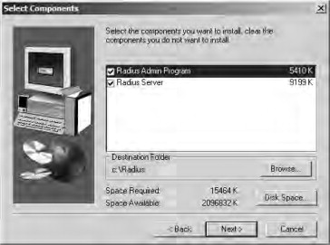
- Select your installation location. Note that you will want to install both the Radius Admin Program and the Radius Server,
shown in Figure 21.47. Click Next to continue.
Figure 21.47. Choosing the installation options and location
- Continue with the installation routine to complete the installation process.
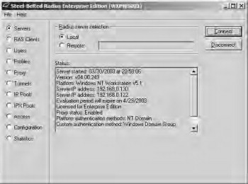
- Ensure that the Yes, launch Radius Administrator option is selected, and click Finish. Once the installation has completed, the Admin application opens. Select the Local option and click the Connect button. If the display you see is something like that shown in Figure 21.48, you’ve successfully installed SBR.
Figure 21.48. Launching the admin application
- Close the SBR Admin application to begin the configuration of SBR for LEAP.
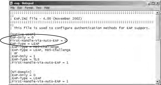
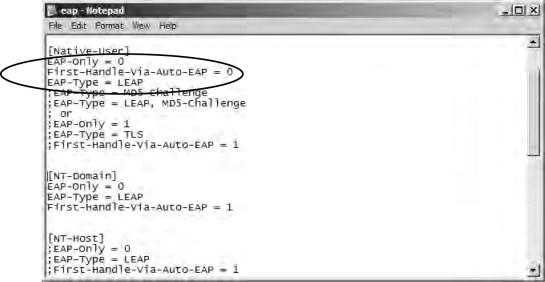
- Navigate to the SBR. installation directory and open the Service folder. Locate and open the eap.ini file for editing. For this example, we use native RADIUS authentication, meaning that users will be authenticating directly
against the SBR RADIUS database. (You can, optionally, configure SBR for Windows domain authentication, as discussed later
in this chapter.) Under the [Native-User] heading, remove the semicolon from the first three items to enable LEAP. Save and close the eap.ini file (see Figure 21.49).
Figure 21.49. Configuring SBR for LEAP
- Restart the Steel Belted Radius service to force it to reload the eap.ini file from the Services console located in the Administrative Tools folder. Launch the SBR Admin application and connect to the local server.
- Click the RAS Clients option to configure SBR for the Cisco Access Point, as shown in Figure 21.50. Note that the AP is the RAS client since it is performing authentication on behalf of the wireless network client. Click
the Add button to create a new client, and click OK to confirm it. Next, specify the client IP address (the IP address assigned to the AP) and the type of client (Cisco Aironet
Access Point).
Figure 21.50. Configuring the RAS client properties

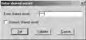
- Click the Edit authentication shared secret button. This will enter the shared secret to be used for the AP and SBR server to authenticate
each other, as shown in Figure 21.51. After entering your shared secret, click the Set button to confirm it. (Remember your shared secret; you will need it again
when you configure the AP later.) Click the Save button on the RAS Clients page to confirm the client details.
Figure 21.51. Entering the shared secret
- Click the Users option to create native users (users internal to the SBR server), as shown in Figure 21.52. Click the Add button to add a new username. After entering the username, click OK to confirm it.
Figure 21.52. Creating native users
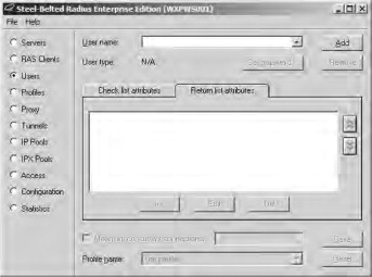
- Click the Set password button to open the Enter User Password dialog box shown in Figure 21.53. You need to leave the Allow PAP or CHAP option selected because LEAP actually makes use of an MS CHAPv1 derivative. After setting the password, click the Set button to confirm it. Click the Save button on the Users page to confirm the user.
Figure 21.53. Entering the user password

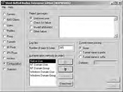
- Click the Configuration option to set the authentication methods (and their order) to be used, as shown in Figure 21.54. Since we are using native users, ensure that the Native User option is placed first in the list. Click Save to confirm the change if required.
Figure 21.54. Selecting the authentication methods

21.5.4. Configuring LEAP
Once you’ve gotten your RADIUS server installed and configured, the hard work is behind you. All that is left now is to configure LEAP on the AP and client network adapter. To configure LEAP on the AP, perform the following steps. (Note that the exact screen will vary among the 350, 1100, and 1200 APs—the end configuration is the same, however. For this discussion, a Cisco Aironet 1100 AP is used with all configurations performed via the Web interface instead of the CLI.)
- Log in to your AP via the Web interface.
- Configure your network SSID and enable EAP authentication, as shown in Figure 21.55. Save your settings to the AP after configuring them.
Figure 21.55. Enabling EAP authentication

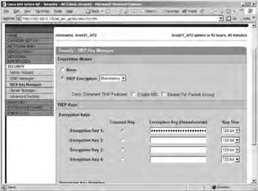
- Enter a 128-bit broadcast WEP key, as shown in Figure 21.56. Save your settings to the AP after configuring them.
Figure 21.56. Entering the broadcast WEP key
- Configure your RADIUS server IP address and shared-secret key information, as shown in Figure 21.57. In addition, you need to ensure that the EAP Authentication option is selected. Save your settings to the AP after configuring them. If you want to enable a reauthentication policy,
you can do so from the Advanced Security-EAP Authentication page shown in Figure 21.58. The default option is Disable Reauthentication. Save your settings to the AP after configuring them.
Figure 21.57. Configuring the RADIUS server information
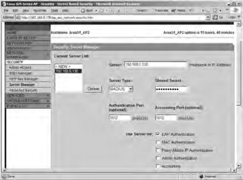
Figure 21.58. Configuring reauthentication.

To enable the wireless client for LEAP, first ensure that it is using the most recent firmware and drivers. Once you’ve got the most up-to-date files, proceed as follows to get the client configured and authenticated using LEAP:
- Launch the Cisco Aironet Client Utility (ACU), shown in Figure 21.59. Notice that the ACU reports that the network adapter is not associated with the AP. This is normal at this point because the AP is configured to require LEAP authentication.
Figure 21.59. Using the Cisco ACU

- Click the Profile Manager button to create a new profile, as shown in Figure 21.60. Click the Add button to enter the new profile name, and then click the OK button to begin configuring the profile.
Figure 21.60. Creating a new profile

- Enter the correct SSID for your network (as previously configured for the AP) on the System Parameters tab, shown in Figure 21.61.
Figure 21.61. Configuring the SSlD for the profile

- Switch to the Network Security tab and select LEAP from the drop-down list, as shown in Figure 21.62. After selecting LEAP, click the Configure button.
Figure 21.62. Configuring the authentication method

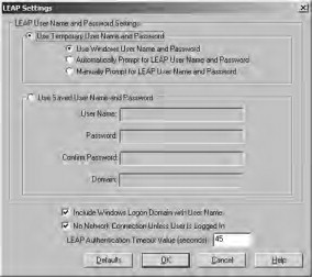
- Ensure that the Use Temporary User Name and Password option is selected with the Automatically Prompt for LEAP User Name and Password suboption on the LEAP Settings page. Remove the check mark from the Include Windows Logon Domain with User Name option because we are using Native mode authentication in this example. Click OK after making your configuration (see Figure 21.63).
Figure 21.63. Configuring LEAP options

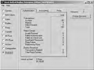
- Click OK twice more and you will be prompted with the LEAP login dialog box shown in Figure 21.64. Enter your details and click OK. If you look at the SBR Admin application on the Statistics page, you can see successful and failed authentications. Notice
that the statistics shown in Figure 21.65 represent clients that are being forced to reauthenticate to the RADIUS server fairly often.
Figure 21.64. Logging into the wireless network using LEAP
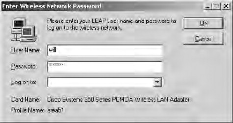
Figure 21.65. Monitoring the RADIUS server statistics
21.5.5. Windows Active Directory Domain Authentication with LEAP and RADIUS
In the preceding sections, we only looked at creating native users in Steel Belted Radius. As mentioned, however, you can create AD domain users and authenticate directly against Active Directory. This offers many advantages, such as preventing dictionary attacks by enforcing account lockout policies. If you want to use domain user accounts for LEAP authentication, you need only perform the following additions and modifications to the procedures we outlined earlier in this chapter:
- Make modifications to the eap.ini file, as shown in Figure 21.66. Under the [NT-Domain] heading, remove the semicolon from the first three items to enable LEAP. Save and close the eap.ini file.
Figure 21.66. Modifying the eap.ini file for domain authentication
- Restart the Steel Belted Radius service to force it to reload the eap.ini file from the Services console located in the Administrative Tools folder, Launch the SBR Admin application and connect to the local server. On the Configuration page, shown in Figure 21.67, ensure that the NT Domain User and NT Domain Group options are enabled and are at, or near, the top of the list. Click Save to confirm the change if required.
Figure 21.67. Checking authentication methods
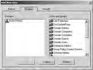
- Go to the Users page and add a new user, as described previously. This time, however, you will have the option to select a domain user, as
shown in Figure 21.68. Select your domain user and click OK. Click Save to confirm the addition of the domain user.
Figure 21.68. Adding a domain user
- Open the ACU and edit the profile in use (the one you previously created). Switch to the Network Security tab and click the Configure button next to the Network Security Type drop-down (where LEAP is selected). Ensure that the Use Windows User Name and Password option is selected, as shown in Figure 21.69. In addition, ensure that a check is placed next to the Include Windows Logon Domain with User Name option.
Figure 21.69. Configuring LEAP options for domain authentication
- Click OK three times to save and exit the profile configuration.
- Log in to the network using LEAP and your domain user credentials.
21.5.6. LEAP Review
Now that you’ve had a chance to examine the workings of Cisco’s LEAP, you should see quite a few benefits to be gained through its use. LEAP, implemented with Funk Software’s Steel Belted Radius, is an ideal and very robust security solution for a wireless network of any size. By forcing users to authenticate to a back-end RADIUS server and creating per-user, per-session dynamic WEP keys, LEAP provides greatly enhanced authentication and security for your wireless network.
LEAP addresses all WEP’s vulnerabilities and is being implemented into the 802.11b standard by the Wi-Fi Alliance (www.wi-fialliance.org), which has implemented LEAP into its standards under the name of Wi-Fi Protected Access (WPA). You can read more about WPA at the Wi-Fi Alliance Web site. In addition, Cisco has licensed the LEAP technology to several third-party vendors, so you can expect to see many more LEAP-compatible devices in the near future. For example, Apple’s AirPort network adapter already supports LEAP with version 2 or better firmware.
21.6. Understanding and Configuring 802.1X RADIUS Authentication
To provide better security for wireless LANs, and in particular to improve the security of WEP, a number of existing technologies used on wired networks were adapted for this purpose, including:
- Remote Authentication and Dial-In User Service (RADIUS). Provides for centralized authentication and accounting.
- 802.1X. Provides for a method of port-based authentication to LAN ports in a switched network environment.
These two services are used in combination with other security mechanisms, such as those provided by the Extensible Authentication Protocol (EAP), to further enhance the protection of wireless networks. Like MAC filtering, 802.1X is implemented at layer 2 of the Open System Interconnection (OSI) model: it will prevent communication on the network using higher layers of the OSI model if authentication fails at the MAC layer. However, unlike MAC filtering, 802.1X is very secure as it relies on mechanisms that are much harder to compromise than MAC address filters, which can be easily compromised through spoofed MAC addresses.
Although a number of vendors implement their own RADIUS servers, security mechanisms, and protocols for securing networks through 802.1X, such as Cisco’s LEAP and Funk Software’s EAP-TTLS, this section will focus on implementing 802.1X on a Microsoft network using Internet Authentication Services (IAS) and Microsoft’s Certificate Services. Keep in mind, however, that wireless security standards are a moving target, and standards other than those discussed here, such as the PEAP, are being developed and might be available now or in the near future.
21.6.1. Microsoft RADIUS Servers
Microsoft’s IAS provides a standards-based RADIUS server and can be installed as an optional component on Microsoft Windows 2000 and Net servers. Originally designed to provide a means to centralize the authentication, authorization, and accounting for dial-in users, RADIUS servers are now used to provide these services for other types of network access, including VPNs, port-based authentication on switches, and, importantly, wireless network access. IAS can be deployed within Active Directory to use the Active Directory database to centrally manage the login process for users connecting over a variety of network types. Moreover, multiple RADIUS servers can be installed and configured so that secondary RADIUS servers will automatically be used in case the primary RADIUS server fails, thus providing fault tolerance for the RADIUS infrastructure. Although RADIUS is not required to support the 802.1X standard, it is a preferred method for providing the authentication and authorization of users and devices attempting to connect to devices that use 802.1X for access control.
21.6.2. The 802.1X Standard
The 802.1X standard was developed to provide a means of restricting port-based Ethernet network access to valid users and devices. When a computer attempts to connect to a port on a network device, such as switch, it must be successfully authenticated before it can communicate on the network using the port. In other words, communication on the network is impossible without an initial successful authentication.
21.6.2.1. 802.1X Authentication Ports
Two types of ports are defined for 802.1X authentication: authenticator or supplicant. The supplicant is the port requesting network access. The authenticator is the port that allows or denies access for network access. However, the authenticator does not perform the actual authentication of the supplicant requesting access. The authentication of the supplicant is performed by a separate authentication service, located on a separate server or built into the device itself, on behalf of the authenticator. If the authenticating server successfully authenticates the supplicant, it will communicate the fact to the authenticator, which will subsequently allow access.
An 802.1X-compliant device has two logical ports associated with the physical port: an uncontrolled port and a controlled port. Because the supplicant must initially communicate with the authenticator to make an authentication request, an 802.1X-compliant device will make use of a logical uncontrolled port over which this request can be made. Using the uncontrolled port, the authenticator will forward the authentication request to the authentication service. If the request is successful, the authenticator will allow communication on the LAN via the logical controlled port.
21.6.2.2. The Extensible Authentication Protocol
EAP is used to pass authentication requests between the supplicant and a RADIUS server via the authenticator. EAP provides a way to use different authentication types in addition to the standard authentication mechanisms provided by the Point-to-Point Protocol (PPP). Using EAR stronger authentication types can be implemented within PPP, such as those that use public keys in conjunction with smart cards. In Windows, there is support for two EAP types:
- EAP MD-5 CHAP. Allows for authentication based on a username/password combination. There are a number of disadvantages associated with using EAP MD-5 CHAP. First, even though it uses one-way hashes in combination with a challenge/response mechanism, critical information is still sent in the dear, making it vulnerable to compromise. Second, it does not provide mutual authentication between the client and the server; the server merely authenticates the client. Third, it does not provide a mechanism for establishing a secure channel between the client and the server.
- EAP-TLS. A security mechanism based on X.509 digital certificates that is more secure than EAP MD-5 CHAP. The certificates can be stored in the Registry or on devices such as smart cards. When EAP- TLS authentication is used, both the client and server validate one another by exchanging X.509 certificates as part of the authentication process. Additionally, EAP-TLS provides a secure mechanism for the exchange of keys to establish an encrypted channel. Although the use of EAP-TLS is more difficult to configure, in that it requires the implementation of a public key infrastructure (PKI)—not a trivial undertaking—EAP-TLS is recommended for wireless 802.1X authentication.
In a paper published in February, 2002 by William A. Arbaugh and Arunesh Mishra entitled “An Initial Security Analysis of the IEEE 802.1x Standard” the authors discuss how one-way authentication and other weaknesses made 802.1X vulnerable to man-in-the-middle and session-hijacking attacks. Therefore, while it might be possible to use EAP MD-5 CHAP for 802.1X wireless authentication on Windows XP (pre SP1), it is not recommended. EAP-TLS protects against the types of attacks described by this paper.
21.6.2.3. The 802.1X Authentication Process
For 802.1X authentication to work on a wireless network, the AP must be able to securely identify traffic from a particular wireless client. This identification is accomplished using authentication keys that are sent to the AP and the wireless client from the RADIUS server. When a wireless client (802.1X supplicant) comes within range of the AP (802.1X authenticator), the following simplified process occurs:
- The AP point issues a challenge to the wireless client.
- The wireless client responds with its identity.
- The AP forwards the identity to the RADIUS server using the uncontrolled port.
- The RADIUS server sends a request to the wireless station via the AP, specifying the authentication mechanism to be used (for example, EAPTLS).
- The wireless station responds to the KADIUS server with its credentials via the AP.
- The RADIUS server sends an encrypted authentication key to the AP if the credentials are acceptable.
- The AP generates a multicast/global authentication key encrypted with a per-station unicast session key, and transmits it to the wireless station.
Figure 21.70 shows a simplified version of the 802.1X authentication process using EAP-TLS.
Figure 21.70. 802.1X authentication process using EAP-TLS

When the authentication process successfully completes, the wireless station is allowed access to the controlled port of the AP, and communication on the network can occur. Note that much of the security negotiation in the preceding steps occurs on the 802.1X uncontrolled port, which is only used so that the AP can forward traffic associated with the security negotiation between the client and the RADIUS server. EAP-TLS is required for the process to take place. EAP-TLS, unlike EAP MD-5 CHAP, provides a mechanism to allow the secure transmission of the authentication keys from the RADIUS server to the client.
21.6.2.4. Advantages of EAP-TLS
There are a number of significant advantages to using EAP-TLS authentication in conjunction with 802.1X:
- The use of X.509 digital certificates for authentication and key exchange is very secure.
- EAP-TLS provides a means to generate and use dynamic one-time-per-user, session-based WEP keys on the wireless network.
- Neither the user nor the administrator know the WEP keys that are in use.
For these reasons, using EAP-TLS for 802.1X authentication removes much of the vulnerability associated with using WEP and provides a high degree of assurance.
In the following section, we will look at how to configure 802.1X using EAP-TLS authentication on a Microsoft-based wireless network. If you are using other operating systems and software, the same general principles will apply. However, you might have additional configuration steps to perform, such as the installation of 802.1X supplicant software on the client. Windows XP provides this software within the operating system.
21.6.3. Configuring 802.1X Using EAP-TLS on a Microsoft Network
Before you can configure 802.1X authentication on a wireless network, you must satisfy a number of prerequisites. At a minimum, you need the following:
Notes from the Underground
Beyond ISA Server
Certificates issued by a Microsoft certification authority (CA) will work for wireless authentication. However, certificates issued by other CAs probably will not work. Certificates that are used for wireless 802.1 X authentication must contain an optional field called Enhanced Key Usage (EKU). The field will contain one or more object identifiers (OlDs) that identify the purpose of the certificate. For example, the EKU of a typical client certificate used for multiple purposes might contain the following values;
- Encrypting File System (1.3,6.1.4.1.311.103.4)
- Secure Email (1.3.6.1.5.5.7.3.4)
- Client Authentication (1.3.6.1.5.5.7.3.2)
The EKU of the certificate installed on the IAS server and the wire-less client for computer authentication will contain a value for server authentication (1.3.6.1.5.5.7.3.1). Because the EKU is an optional field, it might be absent on certificates issued by non-Microsoft CAs, rendering them useless for 802.1 X authentication in a Microsoft infrastructure. Furthermore, the certificate must contain the fully qualified domain name (FQDN) of the computer on which it is installed in the Subject Alternate Name field, and, in the case of certificates used for user authentication, the user principal name (UPN). You can confirm whether these fields and values exist by viewing the properties of the certificate in the Certificates snap-in of the MMC console. (Steps for loading this snap-in are detailed later in this chapter.) There are some other certificate requirements not mentioned here that must be also be satisfied. If you would like to use a third-party CA to issue client certificates for 802.1 X authentication, you should contact the vendor to see if it is supported for this purpose. If not, and you must use a third-party CA, you might need to look at solutions provided by other vendors of wireless hardware to use 802.1 X.
- An AP that supports 802.1X authentication. You probably won’t find these devices at your local computer hardware store. They are designed for enterprise-class wireless network infrastructures, and are typically higher priced. Note that some devices will allow the use of IP Sec between the AP and the wired network.
- Client software and hardware that supports 802.1X and EAP-TLS authentication and the use of dynamic WEP keys. Fortunately, just about any wireless adapter that allows the use of the Windows XP wireless interface will work. However, older wireless network adapters that use their own client software might not work.
- IAS installed on a Windows 2000 server to provide a primary RADIUS server and, optionally, installed on other servers to provide secondary RADIUS servers for fault tolerance.
- Active Directory
- A PKI using a Microsoft stand-alone or Enterprise Certificate server to support the use of X.509 digital certificates for EAP-TLS. More certificate servers can be deployed in the PKI for additional security. An Enterprise Certificate server can ease the burden of certificate deployment to clients and the RADIUS server through auto-enrollment of client computers that are members of the Windows 2000 domain.
- The most recent service packs and patches installed on the Windows 2000 servers and Windows XP wireless clients.
After configuring a PKI and installing IAS on your Windows 2000 network, there are three general steps to configure 802.1X authentication on your wireless network:
- Install X.509 digital certificates on the wireless client and IAS servers.
- Configure IAS logging and policies for 802.1X authentication.
- Configure the wireless AP for 802.1X authentication.
- Configure the properties of the client wireless network interface for dynamic WEP key exchange.
21.6.3.1. Configuring Certificate Services and Installing Certificates on the IAS Server and Wireless Client
After deploying Active Directory, the first step in implementing 802.1X is to deploy the PKI and install the appropriate X.509 certificates. You will have to install (at a minimum) a single certificate server, either a standalone or enterprise certificate server, to issue certificates. What distinguishes a standalone from an enterprise certificate server is whether it will depend on, and be integrated with, Active Directory. A standalone CA does not require Active Directory. This certificate server can be a root CA or a subordinate CA, which ultimately receives its authorization to issue certificates from a root CA higher in the hierarchy, either directly or indirectly through intermediate CAs, according to a certification path.
Note
The certification path can be viewed in the properties of installed certification.
The root CA can be a public or commercially available CA that issues an authorization to a subordinate CA, or one deployed on the Windows 2000 net-work. In enterprise networks that require a high degree of security, it is not recommended that you use the root CA to issue client certificates; for this purpose, you should use a subordinate CA authorized by the root CA. In very high-security environments, you should use intermediate CAs to authorize the CA that issues client certificates. Furthermore, you should secure the hardware and software of the root and intermediate CAs as much as possible, take them offline, and place them in a secure location. You would then bring the root and intermediate CAs online only when you need to perform tasks related to the management of your PKI.
In deploying your PKI, keep in mind that client workstations and the IAS servers need to be able to consult a certificate revocation list (CRL) to verify and validate certificates, especially certificates that have become compromised before their expiration date and have been added to a CRL. If a CRL is not available, authorization will fail. Consequently, a primary design consideration for your PKI is to ensure that the CRLs are highly available. Normally, the CRL is stored on the CA; however, additional distribution points for the CRL can be created to ensure a high degree of availability. The CA maintains a list of these locations and distributes the list in a field of the client certificate.
Note
It is beyond the scope of this book to discuss the implementation details of a PKI. For more information, please see the various documents available on the Microsoft Web site, in particular www.microsoft.com/windows2000/technologies/security/default.asp, www.microsoft.com/windows2000/techinfo/howitworks/security/pkiintro.asp, and www.microsoft.com/windows2000/techinfo/planning/security/pki.asp.
Whether you decide to implement a standalone or an enterprise CA to issue certificates, you will need to issue three certificates: for both the computer and the user account on the wireless client, as well as the RADIUS server. A certificate is required in all of these places because mutual authentication has to take place. The computer certificate provides initial access of the computer to the network, and the user certificate provides wireless access after the user logs in. While the RADIUS server will authenticate the client based on the wireless client’s computer and user certificates, and the wireless client will authenticate the RADIUS server based on the server’s certificate.
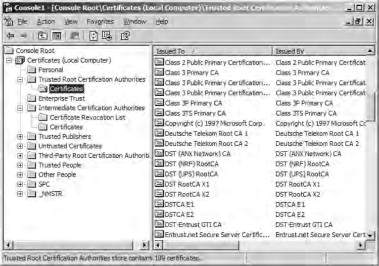
The certificates on the wireless client and the RADIUS server do not have to be issued by the same CA. However, both the client and the server have to trust each other’s certificates. Within each certificate is information about the certificate path leading up to the root CA. If both the wireless client and the RADIUS server trust the root CA in each other’s certificate, mutual authentication can successfully take place. If you are using a standalone CA that is not in the list of Trusted Root Certification Authorities, you will have to add it to the list. You can do this through a Group Policy Object, or you can do it manually. For information on how to add CAs to the Trusted Root Certification Authorities container, please see Windows 2000 and Windows XP help files. The container listing these trusted root certificates can be viewed in the Certificates snap-in of the MMC console, as shown in Figure 21.71.
Figure 21.71. Certificate snap-in showing trusted root certification authorities
Using an enterprise CA will simplify many of the tasks related to certificates that you have to perform. An enterprise CA is automatically listed in the Trusted Root Certification Authorities container. Furthermore, you can use auto-enrollment to issue computer certificates to the wireless client and the IAS server without any intervention on the part of the user. Using an enterprise CA and configuring auto-enrollment of computer certificates should be considered a best practice.
If you put an enterprise CA into place, you will have to configure an Active Directory Group Policy to issue computer certificates automatically. You should use the Default Domain Policy for the domain in which your CA is located. To configure the Group Policy for auto-enrolment of computer certificates, do the following:
- Access the Properties of the Group Policy object for the domain to which the enterprise CA belongs using Active Directory Users and Computers, and click Edit.
- Navigate to Computer Settings | Windows Settings | Security Settings | Public Key Policies | Automatic Certificate Request Settings.
- Right click the Automatic Certificate Request Settings with the, click New, and then click Automatic Certificate Request, as in Figure 21.72.
Figure 21.72. Configuring a domain group policy for auto-enrollment of computer certificates

- Click Next when the wizard appears. Click Computer in the Certificate Templates, as shown in Figure 21.73, and then click Next.
Figure 21.73. Choosing a computer certificate template for auto-enrollment

- Click the enterprise CA, click Next, and then click Finish.
After you have configured a Group Policy for auto-enrollment of computer certificates, you can force a refresh of the group policy so that it will take effect immediately, rather than waiting for the next polling interval for Group Policy Changes, which could take as long as 90 minutes. To force Group Policy to take effect immediately on a Windows XP computer, type the command gpupdate/target: computer.
Note
On a Windows 2000 client, group policy update is forced by using the secedit/refreshpolicy command.
Once you have forced a refresh of group policy, you can confirm if the computer certificate is successfully installed. To confirm the installation of the computer certificate:
- Type the command mmc and click OK from Start | Run.
- Click File in the MMC console menu, and then click Add/Remove Snap-in.
- Click Add in the Add/Remove Snap-in dialog box. Then, select Certificates from the list of snap-ins and check Add. You will be prompted to choose which certificate store the snap-in will be used to manage.
- Select computer account when prompted about what certificate the snap-in will be used to manage, and then check Next. You will then be prompted to select the computer the snap-in will manage.
- Select Local computer (the computer this console is running on) and check Finish. Then, check Close and check OK to close the remaining dialog boxes.
- Navigate to the Console Root | Certificates (Local Computer) | Personal | Certificates container, as seen in a display similar to the one in Figure 21.73. The certificate should be installed there.
The next step is to install a user certificate on the client workstation and then map the certificate to a user account. There are a number of ways to install a user certificate: through Web enrollment: by requesting the certificate using the Certificates snap-in, by using a CAPICOM script (which can be executed as a login script to facilitate deployment), or by importing a certificate file.
The following steps demonstrate how to request the certificate using the Certificates snap-in:
- Open an MMC console for Certificates—Current User. (To load this snap-in, follow the steps in the preceding procedure; however, at step 5, select My user account.)
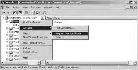
- Navigate to Certificates | Personal and check the container with the alternate mouse button. Highlight All Tasks and then check Request New Certificate, as shown in Figure 21.74. The Certificate Request Wizard appears.
Figure 21.74. Requesting a user certificate
- Click Next on the Certificate Request Wizard welcome page.
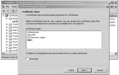
- Select User and click Next on the Certificate Types, as shown in Figure 21.75. You can also select the Advanced check box. Doing so will allow you to select from a number of different cryptographic service providers (CSPs), to choose
a key length, to mark the private key as exportable (the option might not be available for selection), and to enable strong
private key protection. The latter option will cause you to be prompted for a password every time the private key is accessed.
Figure 21.75. Choosing a certificate type
- Type in a Friendly Name of your choosing and a Description, and then click Next.
- Review your settings and click Finish.
You now should have a user certificate stored on the computer used for wireless access. However, this user certificate will not be usable for 802.1X authentication unless it is mapped to a user account in Active Directory. By default, the certificate should be mapped to the user account. You can verify if it has been mapped by viewing the Properties of the user account in Active Directory Users and Computers. The certificates that are mapped to the user account can be viewed in the Published Certificates tab of the Properties of the user account object.
After you configure certificate services and install computer and user certificates on the wireless client and a computer certificate on the RADIUS server, you must configure the RADIUS server for 802.1X authentication.
21.6.3.2. Configuring IAS Server for 802.1X Authentication
If you have configured RRAS for dial-in or VPN access, you will be comfortable with the IAS Server interface. It uses the same interfaces for configuring dial-in conditions and policies as does RRAS. You can use IAS to centralize dial-in access policies for your entire network, rather than have dial-in access policies defined on each RRAS server. A primary advantage of doing this is easier administration and centralized logging of dial-in access.
Installing an IAS server also provides a standards-based RADIUS server that is required for 802.1X authentication. As with configuring RRAS, you will need to add and configure a Remote Access Policy to grant access. A Remote Access Policy grants or denies access to remote users and devices based on matching conditions and a profile. For access to be granted, the conditions you define have to match. For example, the dial-in user might have to belong to the appropriate group, or connect during an allowable period. The profile in the Remote Access Policy defines such things as the authentication type and the encryption type used for the remote access. If the remote client is not capable of using the authentication methods and encryption strength defined in the profile, access is denied.
For 802.1X authentication, you will have to configure a Remote Access Policy that contains conditions specific to 802.1X wireless authentication and a Profile that requires the use of the Extensible Authentication Protocol (EAP) and strong encryption. After configuring the Remote Access Policy, you will have to configure the IAS server to act as a RADIUS server for the wireless AP, which is the RADIUS client.
Before installing and configuring the IAS server on your Windows 2000 or .NET/2003 network, you should consider whether you are installing it on a domain controller or member server (in the same or in a different domain). If you install it on a domain controller, the IAS server will be able to read the account properties in Active Directory. However, if you install IAS on a member server, you will have to perform an additional step to register the IAS server, which will give it access to Active Directory accounts.
There are a number of ways you can register the IAS server:
Note
Perhaps the simplest way to register the IAS server is through the netsh command. To do this, log on to the IAS server, open a command prompt, and type the command netsh ras add registeredserver. If the IAS server is in a different domain, you will have to add arguments to this command. For more information on registering IAS servers, see Windows Help.
- The IAS snap-in
- The Active Directory Users and Computers admin tool
- The netsh command
Once you have installed and, if necessary, registered the IAS server(s), you can configure the Remote Access Policy. Before configuring a Remote Access Policy, make sure that you apply the latest service pack and confirm that the IAS server has an X.509 computer certificate. In addition, you should create an Active Directory Global or Universal Group that contains your wireless users as members.
The Remote Access Policy will need to contain a condition for NAS-Port-Type that contains values for Wireless-Other and Wireless-IEEE802.11 (these two values are used as logical OR for this condition) and a condition for Windows-Groups=[the group created for wireless users]. Both conditions have to match (logical AND) for access to be granted by the policy.
The Profile of the Remote Access Policy will need to be configured to use the Extensible Authentication Protocol, and the Smart Card or Other Certificate EAP type. Encryption in the Profile should be configured to force the strongest level of encryption, if supported by the AP. Depending on the AP you are using, you might have to configure vendor specific attributes (VSA) in the Advanced tab of the Profile. If you have to configure a VSA, you will need to contact the vendor of the AP to find out the value that should be used, if you can’t find it in the documentation.
To configure the conditions for a Remote Access Policy on the IAS server:
- Select Internet Authentication Services and open the IAS console from Start |Programs |Administrative Tools.
- Right click Remote Access Policies, and from the subsequent context menu, click New Remote Access Policy.
- Enter a friendly name for the policy and click Next.
- Click Add in the Add Remote Access Policy Conditions dialog box. Then, select NAS-Port-Type in the Select Attribute dialog
box and click Add, as shown in Figure 21.76.
Figure 21.76. Adding a NAS-port-type condition to remote access policy

- Select Wireless-IEEE 802.11 and Wireless—Other from the left-hand window in the NAS-Port-Type dialog, and click Add>> to move them to the Selected Types window, as shown in Figure 21.77. Click OK.
Figure 21.77. Adding wireless NAS-port-type conditions

- Add a condition for Windows-Groups that contains the group you created for wireless users after configuring the NAS-Port-Type conditions. Then, click Next.
- Click the radio button to Grant remote access permission if user matches conditions in the subsequent Permissions page for the new policy. The next step is to configure the Profile to support EAP-TLS and force the strongest level of encryption (128 bit).
- Click Edit Profile and click the Authentication tab.
- Confirm that the checkbox for Extensible Authentication Protocol is selected and that Smart Card or Other Certificate is listed as the EAP type in the drop-down box. Clear all the other check boxes and click Configure.
- Select the computer certificate you installed for use by the IAS server, and click OK. The resulting Authentication tab should look like the one in Figure 21.78.
Figure 21.78. Configuring the dial-in profile for 802.1X authentication
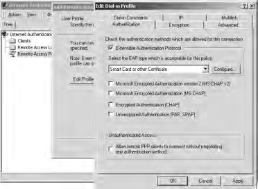
- Force the strongest level of encryption by clicking the Encryption tab and then clearing all the checkboxes except the one for Strongest.
- Save the policy by clicking OK and then Finish. Make sure that the policy you created is higher in the list than the default Remote Access Policy. You can delete the default
policy if you like.
- Finally, you need to configure the IAS server for RADIUS authentication. To do this, you need to add a configuration for the RADIUS client—in this case, the AP—to the IAS server:
- Right click the Clients folder in the IAS console, and click New Client from the context menu.
- Supply a friendly name for the configuration and click Next. The screen shown in Figure 21.79 appears.
Figure 21.79. Adding a RADIUS client
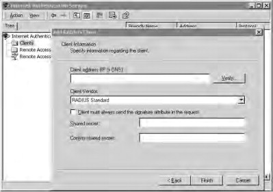
- Configure the screen with the Client address (IP or DNS) of the wireless AE and click the checkbox indicating that the Client must always send the signature attribute in the request. For the Shared secret, add an alphanumeric password that is at least 22 characters long for higher security.
- Check Finish.
You can change the port numbers for RADIUS accounting and authentication by obtaining the properties of the Internet Authentication Service container in the IAS console. You can also use these property pages to log successful and unsuccessful authentication attempts and to register the server in Active Directory.
After installing certificates on the wireless client and IAS server and configuring the IAS server for 802.1X authentication, you will need to configure the AP and the wireless client. The following text shows the typical steps to complete the configuration of your wireless network for 802.1X authentication.
21.6.3.3. Configuring an Access Point for 802.1X Authentication
Generally, only enterprise-class APs support 802.1X authentication; this is not a feature found in devices intended for the SOHO market. Enterprise-class APs are not likely to be found in your local computer store. If you want an AP that supports 802.1X, you should consult the wireless vendors’ Web sites for information on the features supported by the APs they manufacture. Vendors that manufacture 802.1X-capable devices include: 3Com, Agere, Cisco, and others. The price for devices that support 802.1X authentication usually starts at $500 (USD) and can cost considerably more, depending on the vendor and the other features supported by the AP. If you already own an enterprise-class AP, such as an ORiNOCO Access Point 500 or Access Point 1000, 802.1X authentication might not be supported in the original firmware but can be added through a firmware update.
Regardless of the device you purchase, an 802.1X-capable AP will be configured similarly. The following text shows the typical configuration of 802.1X authentication on an ORiNOCO Access Point 500 with the most recent firmware update applied to it.
Note
For more information about the ORiNOCO device, see www.orinocowireless.com.
The configuration of the AP is straightforward and simple (see Figure 21.80). You will need to configure the following:
- An encryption key length. This can be either 64 or 128 bits (or higher if your hardware and software support longer lengths).
- An encryption key lifetime. When you implement 802.1X using EAP-TLS, WEP encryption keys are dynamically generated at intervals you specify. For higher-security environments, the encryption key life-time should be set to ten minutes or less.
- An authorization lifetime. This is the interval at which the client and server willre-authenticate with one another. This interval should be longer than the interval for the encryption key lifetime, but still relatively short in a high-security environment. A primary advantage here is that if a device is stolen, the certificates it uses can be immediately revoked. The next time it tries to authenticate, the CRL will be checked and authentication will fail.
- An authorization password. This is the shared-secret password you configured for RADIUS client authentication on the IAS server. This password is used to establish communication between the AP and the RADIUS server. Thus, it needs to be protected by being long and complex. This password should be at least 22 characters long and use mixed case, numbers, letters, and other characters. You might want to consider using a random string generation program to create this password for you.
- An IP address o f a primary and, if configured for fault tolerance, a secondary RADIUS server. If the AP is in a DMZ, and the RADIUS server is behind a firewall, this IP address can be the external IP address of the firewall.
- A UDP port used for RADIUS authentication. The default port for RADIUS is port 1645. However, you can change this port on the IAS server and the AP for an additional degree of security.
Figure 21.80. Configuring an ORiNOCO AP 500 for 802.1X Authentication
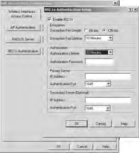
Depending on your AP, you might have to go through additional configuration steps. For example, you might have to enable the use of dynamic WEP keys. On the AP 500, this configuration is automatically applied to the AP when you finish configuring the 802.1X settings. Consult your AP’s documentation for specific information on configuring it for 802.1X authentication.
21.6.3.4. Configuring the Wireless Interface on Windows XP for 802.1X Authentication
If you have been following the preceding steps in the same order for configuring 802.1X authentication, the final step is to configure the properties of the wireless interface in Windows XP. You will have to ensure that the properties for EAP-TLS authentication and dynamic WEP are configured. To do this, perform the following steps:
- Obtain the Properties of the wireless interface and click the Authentication tab.
- Ensure that the checkbox for Enable access control for IEEE 802.1X is checked and that Smart Card or other Certificate is selected as the EAP type, as shown in Figure 21.81.
Figure 21.81. Authentication properties for wireless client
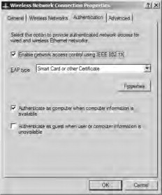
- Check Properties to view the Smart Card or other Certificate Properties window. Ensure that the checkbox for Validate server certificate is checked, as shown in Figure 21.82.
Figure 21.82. Configure Smart Card or other Certificate properties
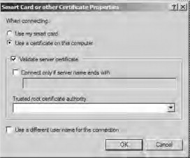
- Select the root CA of the issuer of the server certificate in the Trusted root certificate authority drop-down box. If it is not already present, click OK. For additional security, you could select the checkbox for Connect only if server name ends with and type in the root DNS name—for example, tacteam.net.
- Obtain the properties of the wireless interface and click the Wireless Network tab.
- Confirm that the checkbox for Use Windows for my wireless network settings is selected In the Preferred networks dialog box. Highlight the SSID of the 802.1X-enabled AP, and click Properties.
- Click the checkbox for The key is provided from me automatically, as shown in Figure 21.83, and then click OK.
Figure 21.83. Configuring Windows XP wireless properties for 802.1X authentication
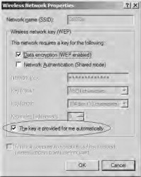
That’s it. You’re finished. The next time you attempt to authenticate and associate with the 802.1X-enabled AP, you might be presented with a prompt asking you to verify the identity of the IAS server certificate. By clicking OK, you will permit the authentication process to complete, thus allowing you secure access to the network.
Let’s briefly review the steps to enable 802.1X authentication. We are assuming that you are using Active Directory, already have a PKI in place, can issue certificates from a Microsoft CA, and have installed and registered (if necessary) an IAS server. Your steps would be as follows:
- Issue computer certificate to IAS server.
- Issue computer certificate to wireless client.
- Issue user certificate to wireless client user.
- Create a Remote Access Policy on the IAS server for 802.1X authentication.
- Configure RADIUS client settings on the IAS server.
- Configure AP for 802.1X authentication.
- Configure wireless client network interface for 802.1X authentication.
Although this might seem like a lot of work, the enhanced security provided by 802.1X might well justify the expense and effort of setting it up. Furthermore, much of the effort is up-front. Since you don’t have to worry about frequently rotating static WEP keys, you will realize significant savings in effort and time later.
802.1X authentication in combination with EAP-TLS is not the final word in wireless security. It mitigates many of the vulnerabilities associated with wireless networks, but other types of attacks might still be possible.
21.7. Summary
Corporate or SOHO wireless networks require a level of security that goes beyond the basics. They have an obligation to protect their business proprietary and customer data. There are many different technologies that can be utilized to accomplish this. WiFi Protected Access (WPA) addresses many of the flaws inherent in WEP. WPA can utilize the Advanced Encryption Standard (AES) to encrypt wireless network transmissions.
Corporate wireless networks should never be deployed without a virtual private network. There are countless commercial VPN products available. Reef Edge Dolphin is a freeware wireless gateway that can be deployed with VPN capabilities. For SOHO users that don’t have the time or the technical staff to deploy and configure a product like Dolphin, Linksys has developed the WRV54G VPN-Broadband Router. The WRV54G provides many enhanced security features. Designed specifically with the small business in mind, the WRV54G provides complete VPN support using IPSec tunnels.
802.1X was originally developed to provide a method for port-based authentication on wired networks. However, it was found to have significant application in wireless networks. With 802.1X authentication, a supplicant (a wireless work-station) needs to be authenticated by an authenticator (usually a RADIUS server) before access is granted to the network. The authentication process takes place over a logical uncontrolled port that is used only for the authentication process. If the authentication process is successful, access is granted to the network on the logical controlled port.
802.1X relies on the Extensible Authentication Protocol (EAP) to perform the authentication. The preferred EAP type for 802.1X is EAP-TLS. EAP-TLS provides the ability to use dynamic per-user, session-based WEP keys, thereby eliminating some of the more significant vulnerabilities associated with WEP. However, to use EAP-TLS, you must deploy a public key infrastructure (PKI) to issue digital X.509 certificates to the wireless clients and the RADIUS server.
21.8. Solutions Fast Track
21.8.1. Implementing WiFi Protected Access (WPA)
- WPA was developed to replace WEP because of the known insecurities associated with WEP’s implementation of the RC4 encryption standard.
- Many of the newer access points support WPA; some require firmware upgrades in order to enable WPA functionality.
- Windows XP is WPA-ready with a patch; however, you must ensure that you have WPA drivers for your wireless card.
21.8.2. Implementing a Wireless Gateway with Reef Edge Dolphin
- Wireless gateways are implemented to control access to the network by authenticating users against an internal or external database.
- Wireless gateways can also perform other tasks, including enforcing security by group, implementing quality of service bandwidth controls, and many other advanced security functions such as VPN tunnels and mobile IP roaming between APs.
- Dolphin is a freeware wireless gateway that provides authentication of users against a local database and optional support for IPSec VPN tunnels for data protection. In a small, noncommercial environment, Dolphin can be quickly and economically put into use to increase network security by controlling wireless network access.
21.8.3. Implementing a VPN on a Linksys WRV54G VPN Broadband Router
- The Linksys WRV54G is a broadband router with a built-in access point and VPN.
- The WRV54G was specifically designed for Small Office/Home Office (SOHO) users that require more than the basic security protection for their wired and wireless networks.
- To utilize the VPN features on the WRV54G an IPSec tunnel must be established between the WRV54G and any clients that access it.
21.8.4. Implementing RADIUS with Cisco LEAP
- LEAP addresses all the problems inherent in the use of WEP in a wireless network. The largest vulnerabilities come from static WEP keys and the predictability of IVs.
- LEAP creates a per-user, per-session dynamic WEP key that is tied to the network logon, thereby addressing the limitations of static WEP keys. Since authentication is performed against a back-end RADIUS database, administrative overhead is minimal after initial installation and configuration.
- Policies can be set to force users to re-authenticate more often to the RADIUS server and thus receive fresh session keys. This can further reduce the window for network attacks because the WEP keys are rotated even more frequently.
- The IV is changed on a per-packet basis, so hackers cannot find a predetermined, predictable sequence to exploit. The capability to change the IV with every packet, combined with the dynamic keying and reauthentication, greatly increases security and makes it that much more difficult for an attacker to gain access to your wireless network.
21.8.5. Understanding and Configuring 802.1X RADIUS Authentication
- RADIUS provides for centralized authentication and accounting.
- 802.1X provides for a method of port-based authentication to LAN ports in a switched network environment.
- For 802.1X authentication to work on a wireless network, the AP must be able to securely identify traffic from a particular wireless client. This identification is accomplished using authentication keys that are sent to the AP and the wireless client from the RADIUS server.