
Chapter 7. Wireless Sensor Networks
7.1. Introduction to Wireless Sensor Networks
Sensors integrated into structures, machinery, and the environment, coupled with the efficient delivery of sensed information, could provide tremendous benefits to society. Potential benefits include: fewer catastrophic failures, conservation of natural resources, improved manufacturing productivity, improved emergency response, and enhanced homeland security [1]. However, barriers to the widespread use of sensors in structures and machines remain. Bundles of lead wires and fiber optic “tails” are subject to breakage and connector failures. Long wire bundles represent a significant installation and long term maintenance cost, limiting the number of sensors that may be deployed, and therefore reducing the overall quality of the data reported. Wireless sensing networks can eliminate these costs, easing installation and eliminating connectors.
The ideal wireless sensor is networked and scaleable, consumes very little power, is smart and software programmable, capable of fast data acquisition, reliable and accurate over the long term, costs little to purchase and install, and requires no real maintenance.
Selecting the optimum sensors and wireless communications link requires knowledge of the application and problem definition. Battery life, sensor update rates, and size are all major design considerations. Examples of low data rate sensors include temperature, humidity, and peak strain captured passively. Examples of high data rate sensors include strain, acceleration, and vibration.
Recent advances have resulted in the ability to integrate sensors, radio communications, and digital electronics into a single integrated circuit (IC) package. This capability is enabling networks of very low cost sensors that are able to communicate with each other using low power wireless data routing protocols. A wireless sensor network (WSN) generally consists of a basestation (or “gateway”) that can communicate with a number of wireless sensors via a radio link. Data is collected at the wireless sensor node, compressed, and transmitted to the gateway directly or, if required, uses other wireless sensor nodes to forward data to the gateway. The transmitted data is then presented to the system by the gateway connection. The purpose of this chapter is to provide a brief technical introduction to wireless sensor networks and present a few applications in which wireless sensor networks are enabling.
7.2. Individual Wireless Sensor Node Architecture
A functional block diagram of a versatile wireless sensing node is provided in Figure 7.1. A modular design approach provides a flexible and versatile platform to address the needs of a wide variety of applications [2]. For example, depending on the sensors to be deployed, the signal conditioning block can be re-programmed or replaced. This allows for a wide variety of different sensors to be used with the wireless sensing node. Similarly, the radio link may be swapped out as required for a given applications’ wireless range requirement and the need for bidirectional communications. The use of flash memory allows the remote nodes to acquire data on command from a basestation, or by an event sensed by one or more inputs to the node. Furthermore, the embedded firmware can be upgraded through the wireless network in the field.
Figure 7.1. Wireless sensor node functional block diagram
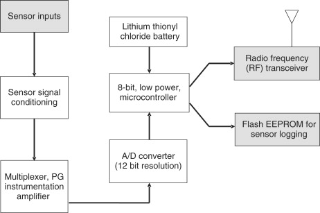
The microprocessor has a number of functions including:
- managing data collection from the sensors
- performing power management functions
- interfacing the sensor data to the physical radio layer
- managing the radio network protocol
A key feature of any wireless sensing node is to minimize the power consumed by the system. Generally, the radio subsystem requires the largest amount of power. Therefore, it is advantageous to send data over the radio network only when required. This sensor event-driven data collection model requires an algorithm to be loaded into the node to determine when to send data based on the sensed event. Additionally, it is important to minimize the power consumed by the sensor itself. Therefore, the hardware should be designed to allow the microprocessor to judiciously control power to the radio, sensor, and sensor signal conditioner.
7.3. Wireless Sensor Networks Architecture
There are a number of different topologies for radio communications networks. A brief discussion of the network topologies that apply to wireless sensor networks are outlined below.
7.3.1. Star Network (Single Point-to-Multipoint)
A star network (Figure 7.2) is a communications topology where a single base-station can send and/or receive a message to a number of remote nodes. The remote nodes can only send or receive a message from the single basestation, they are not permitted to send messages to each other. The advantage of this type of network for wireless sensor networks is in its simplicity and the ability to keep the remote node’s power consumption to a minimum. It also allows for low latency communications between the remote node and the basestation. The disadvantage of such a network is that the basestation must be within radio transmission range of all the individual nodes and is not as robust as other networks due to its dependency on a single node to manage the network.
Figure 7.2. Star network topology

7.3.2. Mesh Network
A mesh network allows for any node in the network to transmit to any other node in the network that is within its radio transmission range. This allows for what is known as multihop communications; that is, if a node wants to send a message to another node that is out of radio communications range, it can use an intermediate node to forward the message to the desired node. This network topology has the advantage of redundancy and scalability. If an individual node fails, a remote node still can communicate to any other node in its range, which in turn, can forward the message to the desired location. In addition, the range of the network is not necessarily limited by the range in between single nodes, it can simply be extended by adding more nodes to the system. The disadvantage of this type of network is in power consumption for the nodes that implement the multihop communications are generally higher than for the nodes that don’t have this capability, often limiting the battery life. Additionally, as the number of communication hops to a destination increases, the time to deliver the message also increases, especially if low power operation of the nodes is a requirement.
Figure 7.3. Mesh network topology
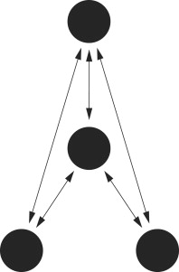
7.3.3. Hybrid Star-Mesh Network
A hybrid between the star and mesh network provides for a robust and versatile communications network, while maintaining the ability to keep the wireless sensor nodes power consumption to a minimum. In this network topology, the lowest power sensor nodes are not enabled with the ability to forward messages. This allows for minimal power consumption to be maintained. However, other nodes on the network are enabled with multihop capability, allowing them to forward messages from the low power nodes to other nodes on the network. Generally, the nodes with the multi-hop capability are higher power, and if possible, are often plugged into the electrical mains line. This is the topology implemented by the up and coming mesh networking standard known as ZigBee.
Figure 7.4. Hybrid star-mesh network topology

7.4. Radio Options for the Physical Layer in Wireless Sensor Networks
The physical radio layer defines the operating frequency, modulation scheme, and hardware interface of the radio to the system. There are many low power proprietary radio integrated circuits that are appropriate choices for the radio layer in wireless sensor networks, including those from companies such as Atmel, MicroChip, Micrel, Melexis, and ChipCon. If possible, it is advantageous to use a radio interface that is standards based. This allows for interoperability among multiple companies networks. A discussion of existing radio standards and how they may or may not apply to wireless sensor networks is given next.
7.4.1. IEEE802.11x
IEEE802.11 is a standard that is meant for local area networking for relatively high bandwidth data transfer between computers or other devices. The data transfer rate ranges from as low as 1 Mbps to over 50 Mbps. Typical transmission range is 300 feet with a standard antenna; the range can be greatly improved with use of a directional high gain antenna. Both frequency hopping and direct sequence spread spectrum modulation schemes are available. While the data rates are certainly high enough for wireless sensor applications, the power requirements generally preclude its use in wireless sensor applications.
7.4.2. Bluetooth (IEEE802.15.1 and .2)
Bluetooth is a personal area network (PAN) standard that is lower power than 802.11. It was originally specified to serve applications such as data transfer from personal computers to peripheral devices such as cell phones or personal digital assistants. Bluetooth uses a star network topology that supports up to seven remote nodes communicating with a single basestation. While some companies have built wireless sensors based on Bluetooth, they have not been met with wide acceptance due to limitations of the Bluetooth protocol including:
- Relatively high power for a short transmission range.
- Nodes take a long time to synchronize to network when returning from sleep mode, which increases average system power.
- Low number of nodes per network (<=7 nodes per piconet).
- Medium access controller (MAC) layer is overly complex when compared to that required for wireless sensor applications.
7.4.3. IEEE 802.15.4
The 802.15.4 standard was specifically designed for the requirements of wireless sensing applications. The standard is very flexible, as it specifies multiple data rates and multiple transmission frequencies. The power requirements are moderately low; however, the hardware is designed to allow for the radio to be put to sleep, which reduces the power to a minimal amount. Additionally, when the node wakes up from sleep mode, rapid synchronization to the network can be achieved. This capability allows for very low average power supply current when the radio can be periodically turned off. The standard supports the following characteristics:
- Transmission frequencies, 868 MHz/902–928 MHz/2.48–2.5 GHz.
- Data rates of 20 Kbps (868 MHz Band) 40 Kbps (902 MHz band) and 250 Kbps (2.4 GHz band).
- Supports star and peer-to-peer (mesh) network connections.
- Standard specifies optional use of AES-128 security for encryption of transmitted data.
- Link quality indication, which is useful for multi-hop mesh networking algorithms.
- Uses direct sequence spread spectrum (DSSS) for robust data communications.
It is expected that of the three aforementioned standards, the IEEE 802.15.4 will become most widely accepted for wireless sensing applications. The 2.4-GHz band will be widely used, as it is essentially a worldwide license-free band. The high data rates accommodated by the 2.4-GHz specification will allow for lower system power due to the lower amount of radio transmission time to transfer data as compared to the lower frequency bands.
7.4.4. ZigBee
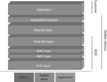
The ZigBee™ Alliance is an association of companies working together to enable reliable, cost-effective, low-power, wirelessly networked monitoring and control products based on an open global standard. The ZigBee alliance specifies the IEEE 802.15.4 as the physical and MAC layer and is seeking to standardize higher level applications such as lighting control and HVAC monitoring. It also serves as the compliance arm to IEEE802.15.4 much as the Wi-Fi alliance served the IEEE802.11 specification. The ZigBee network specification, ratified in 2004, will support both star network and hybrid star mesh networks. As can be seen in Figure 7.5, the ZigBee alliance encompasses the IEEE802.15.4 specification and expands on the network specification and the application interface.
Figure 7.5. ZigBee stack
7.4.5. IEEE1451.5
While the IEEE802.15.4 standard specifies a communication architecture that is appropriate for wireless sensor networks, it stops short of defining specifics about the sensor interface. The IEEE1451.5 wireless sensor working group aims to build on the efforts of previous IEEE1451 smart sensor working groups to standardize the interface of sensors to a wireless network. Currently, the IEEE802.15.4 physical layer has been chosen as the wireless networking communications interface, and at the time of this writing the group is in the process of defining the sensor interface.
7.5. Power Consideration in Wireless Sensor Networks
The single most important consideration for a wireless sensor network is power consumption. While the concept of wireless sensor networks looks practical and exciting on paper, if batteries are going to have to be changed constantly, widespread adoption will not occur. Therefore, when the sensor node is designed power consumption must be minimized. Figure 7.6 shows a chart outlining the major contributors to power consumption in a typical 5000-ohm wireless strain gage sensor node versus transmitted data update rate. Note that by far the largest power consumption is attributable to the radio link itself.
Figure 7.6. Power consumption of a 5000-ohm strain gage wireless sensor node

There are a number of strategies that can be used to reduce the average supply current of the radio, including:
- Reduce the amount of data transmitted through data compression and reduction.
- Lower the transceiver duty cycle and frequency of data transmissions.
- Reduce the frame overhead.
- Implement strict power management mechanisms (power-down and sleep modes).
- Implement an event-driven transmission strategy; only transmit data when a sensor event occurs.
Power reduction strategies for the sensor itself include:
- Turn power on to sensor only when sampling.
- Turn power on to signal conditioning only when sampling sensor.
- Only sample sensor when an event occurs.
- Lower sensor sample rate to the minimum required by the application.
7.6. Applications of Wireless Sensor Networks
7.6.1. Structural Health Monitoring – Smart Structures
Sensors embedded into machines and structures enable condition-based maintenance of these assets [3]. Typically, structures or machines are inspected at regular time intervals, and components may be repaired or replaced based on their hours in service, rather than on their working conditions. This method is expensive if the components are in good working order, and in some cases, scheduled maintenance will not protect the asset if it was damaged in between the inspection intervals. Wireless sensing will allow assets to be inspected when the sensors indicate that there may be a problem, reducing the cost of maintenance and preventing catastrophic failure in the event that damage is detected. Additionally, the use of wireless reduces the initial deployment costs, as the cost of installing long cable runs is often prohibitive.
In some cases, wireless sensing applications demand the elimination of not only lead wires, but the elimination of batteries as well, due to the inherent nature of the machine, structure, or materials under test. These applications include sensors mounted on continuously rotating parts [4], within concrete and composite materials [5], and within medical implants [6,7].
7.6.2. Industrial Automation
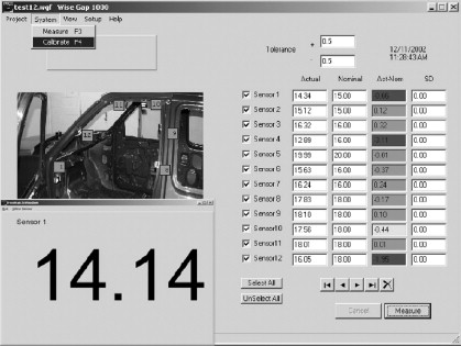
In addition to being expensive, leadwires can be constraining, especially when moving parts are involved. The use of wireless sensors allows for rapid installation of sensing equipment and allows access to locations that would not be practical if cables were attached. An example of such an application on a production line is shown in Figure 7.7. In this application, typically ten or more sensors are used to measure gaps where rubber seals are to be placed. Previously, the use of wired sensors was too cumbersome to be implemented in a production line environment. The use of wireless sensors in this application is enabling, allowing a measurement to be made that was not previously practical [8].
Figure 7.7. Industrial application of wireless sensors
Other applications include energy control systems, security, wind turbine health monitoring, environmental monitoring, location-based services for logistics, and health care.
7.6.3. Application Highlight – Civil Structure Monitoring
One of the most recent applications of today’s smarter, energy-aware sensor networks is structural health monitoring of large civil structures, such as the Ben Franklin Bridge (Figure 7.8), which spans the Delaware River, linking Philadelphia and Camden, N.J [9,10]. The bridge carries automobile, train and pedestrian traffic. Bridge officials wanted to monitor the strains on the structure as high-speed commuter trains crossed over the bridge.
Figure 7.8. Ben Franklin Bridge

A star network of ten strain sensors was deployed on the tracks of the commuter rail train. The wireless sensing nodes were packaged in environmentally sealed NEMA rated enclosures. The strain gages were also suitably sealed from the environment and were spot welded to the surface of the bridge steel support structure. Transmission range of the sensors on this star network was approximately 100 meters.
The sensors operate in a low-power sampling mode where they check for presence of a train by sampling the strain sensors at a low sampling rate of approximately 6 Hz.When a train is present the strain increases on the rail, which is detected by the sensors. Once detected, the system starts sampling at a much higher sample rate. The strain waveform is logged into local Flash memory on the wireless sensor nodes. Periodically, the waveforms are downloaded from the wireless sensors to the basestation. The basestation has a cell phone attached to it which allows for the collected data to be transferred via the cell network to the engineers’ office for data analysis.
This low-power event-driven data collection method reduces the power required for continuous operation from 30 mA if the sensors were on all the time to less than 1 mA continuous. This enables a lithium battery to provide more than a year of continuous operation.
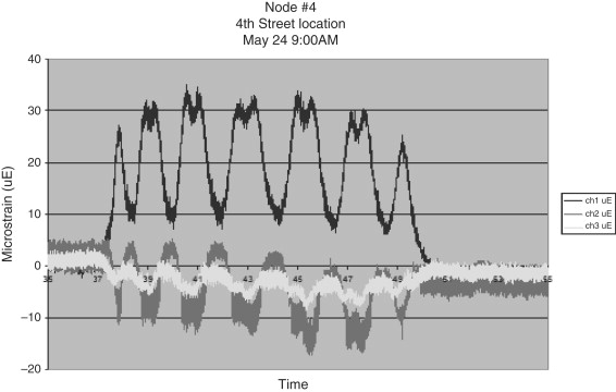
Resolution of the collected strain data was typically less than 1 microstrain. A typical waveform downloaded from the node is shown in Figure 7.9. Other performance specifications for these wireless strain sensing nodes have been provided in an earlier work [11].
Figure 7.9. Bridge strain data
7.7. Future Developments
The most general and versatile deployments of wireless sensing networks demand that batteries be deployed. Future work is being performed on systems that exploit piezoelectric materials to harvest ambient strain energy for energy storage in capacitors and/or rechargeable batteries. By combining smart, energy saving electronics with advanced thin film battery chemistries that permit infinite recharge cycles, these systems could provide a long term, maintenance free, wireless monitoring solution [12].