
Chapter 5. Infrared Communication Basics
5.1. The Ir Spectrum
The infrared (Ir) part of the electromagnetic spectrum covers radiation having a wavelength in the range from roughly 0.78 μm to 1000 μm (1 mm). Infrared radiation takes over from extremely high frequency (EHF) at 300 GHz and extends to just below the red end of the visible light spectrum at around 0.76 μm wavelength. Unlike radio frequency radiation, which is transmitted from an antenna when excited by an oscillating electrical signal, infrared radiation is generated by the rotational and vibrational oscillations of molecules.
The infrared spectrum is usually divided into three regions, near, middle and far, where “near” means nearest to visible light (Table 5.1). Although all infrared radiation is invisible to the human eye, far infrared is experienced as thermal, or heat, radiation. Rather than using frequency as an alternative to wavelength, as is commonly done in the RF region, the wavenumber is used instead in the infrared region. This is the reciprocal of the wavelength and is usually expressed as the number of wavelengths per centimeter.
Table 5.1. Subdivision of the infrared spectrum
| Infrared region | Wavelength (μm) | Wavenumber (/cm) |
|---|---|---|
| Near | 0.78–2.5 | 12,800–4000 |
| Middle | 2.5–50 | 4000–200 |
| Far | 2.5–50 | 200–10 |
One aspect of wireless communication that becomes simpler outside the RF region is spectrum regulation, since the remit of the FCC and equivalent international agencies runs out at 300 GHz or 1 mm wavelength.
5.2. Infrared Propagation and Reception
The near infrared is the region used in data communications, largely as a result of the cheap availability of infrared emitting LEDs and optodetectors, solid-state devices that convert an electrical current directly into infrared radiation and vice versa. Infrared LEDs emit at discrete wavelengths in the range from 0.78 to 1.0 μm, the specific wavelength of the LED being determined by the particular molecular oscillation that is used to generate the radiation.
5.2.1. Transmitted Power Density—Radiant Intensity
Ir propagation is generally a simpler topic than RF propagation, although the same principles, such as the concept of a link budget, still apply. The link budget predicts how much transmitter power is required to enable the received data stream to be decoded at an acceptable BER. For Ir, the link budget calculation is far simpler than for RF, as terms like antenna gain, free space loss and multipath fading, discussed in the last chapter, no longer apply. As a result, propagation behavior can be more easily predicted for Ir than for RF.
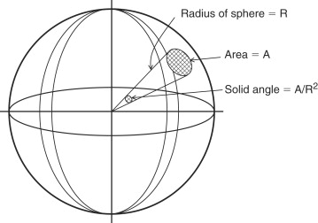
The unit of infrared power intensity, or radiant intensity, is mW/sr, with sr being the abbreviation for steradian. The steradian is the unit of solid angle measure, and this is the key concept in understanding the link budget for Ir communication. As shown in Figure 5.1, the solid angle (S) subtended by an area A on the surface of a sphere of radius R is given as:(5-1)
![]()
Figure 5.1. Solid angle subtended by an area
![]()
Note from Eq. 5-1 that at a distance of 1 meter a solid angle of 1 steradian subtends an area of 1 m2. For small solid angles, the area A on the sphere can be approximated by the area of the flat circle of radius r, giving:
![]()
As an example, the IrDA physical layer standard specifies a half angle (a) of between 15° and 30°. For 15°, S=2π(1−cos(15°))=0.214 steradians.
For an LED with a given emitter power density or radiant intensity, Ie, in mW/sr, the equivalent power density in mW/m2 will be approximately given as:(5-3)
![]()
5.2.2. Emitter Beam Pattern
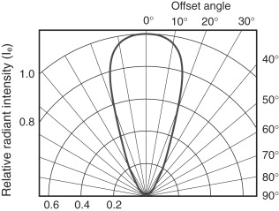
Similar to an RF antenna, an LED has a beam pattern in which radiated power drops off with increasing angle off-axis. In the example shown in Figure 5.2, the power density drops to about 85% of the on-axis value at an off-axis angle of 15°.
Figure 5.2. Typical LED emitted power polar diagram
5.2.3. Inverse Square Loss
Equation 5-3 shows that the on-axis power density is inversely proportional to the square of the distance from the source. If R is doubled, the power density P drops by a factor of 4, as shown in Figure 5.3. This is the equivalent of the free space loss term in the RF link budget.
Figure 5.3. Inverse square distance relationship of radiant power density

5.2.4. Ir Detector Sensitivity
The standard detection device for high-speed Ir communications is the photodiode, which has a detection sensitivity, or minimum threshold irradiance Ee, expressed in μW/cm2. In standard power mode, the IrDA standard specifies a minimum emitter power of 40 mW/sr. From Eq. 5-3, the minimum power density at a receiving photodiode at a range of 1 meter will be 40 mW/m2, or 4 μW/cm2.
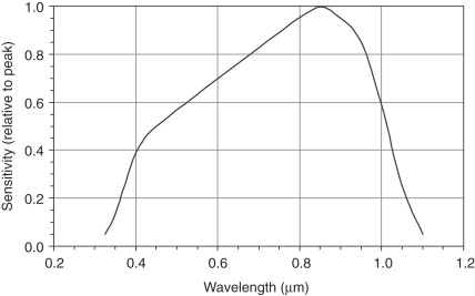
The sensitivity of a photo diode detector depends on the incident angle of the infrared source relative to the detector axis in a similar manner to that shown in Figure 5.2 for the beam pattern of an LED. Photodiode sensitivity also depends on the incident infrared wavelength as shown for example in Figure 5.4, and in any application a detector will be chosen with a peak spectral sensitivity close to the wavelength of the emitting device.
Figure 5.4. Typical photodiode sensitivity vs. wavelength
5.2.5. Ir Link Distance
The maximum link distance for an Ir link can be calculated as the distance R at which the equivalent power density (P) drops to the level of the detector's minimum threshold irradiance (Ee). Eq. 5-3 gives:
![]()
![]()
The effective range of an Ir link can be increased substantially, up to several tens of meters, using lenses to collimate the transmitted beam and focus the beam onto the receiving photodiode. Alignment of the lenses and of the transmitting and receiving diodes will be critical to the effectiveness of such a system. As shown in Figure 5.5, a misalignment of approximately 1/3° would be sufficient to break a focused link over a range of 10 m.
Figure 5.5. Focused Ir link alignment over a 10 m range

Ir areal coverage may be increased in a home or small office environment by reflecting the Ir beam from a wall or ceiling in order to access a number of devices. In order to preserve power in the reflection it will be important to use a high reflectance, low absorption material to reflect the beam. A white painted ceiling is a good reflector of sunlight, with a reflection coefficient for visible light of around 0.9, but is a poor reflector at Ir wavelengths, absorbing about 90% of the incident Ir radiation. To achieve a comparable 0.9 reflection coefficient for Ir, an aluminum or aluminum foil covered panel would be a suitable reflector.
5.3. Summary
Like the radio frequency technology discussed in the last chapter, the infrared communication technologies described in this chapter are at the heart of the physical layer of wireless networks. An understanding of the basics of these two technologies will provide a firm foundation from which to discuss the implementation of wireless networks, whether local, personal or metropolitan area (LAN, PAN or MAN).
In particular, the link budget calculation will be important in establishing power requirements and coverage in LAN and MAN applications. Spread spectrum and digital modulation techniques are key to understanding how a wide range of data rates can be accommodated within the limited available bandwidth, for example in the 2.4 and 5.8 GHz ISM bands.
Infrared communication links are perhaps the most “transparent” in terms of a very low requirement for user configuration, and to some extent this means that the user can be unconcerned about the underlying technology. However, even infrared links can be stretched to deliver performance over significant distances (tens of meters), given an understanding of the characteristics of Ir transmitters, detectors and infrared propagation.