
Chapter 2. Wireless Network Logical Architecture
The logical architecture of a network refers to the structure of standards and protocols that enable connections to be established between physical devices, or nodes, and which control the routing and flow of data between these nodes.
Since logical connections operate over physical links, the logical and physical architectures rely on each other, but the two also have a high degree of independence, as the physical configuration of a network can be changed without changing its logical architecture, and the same physical network can in many cases support different sets of standards and protocols.
The logical architecture of wireless networks will be described in this chapter with reference to the OSI model.
2.1. The OSI Network Model
The Open Systems Interconnect (OSI) model was developed by the International Standards Organization (ISO) to provide a guideline for the development of standards for interconnecting computing devices. The OSI model is a framework for developing these standards rather than a standard itself—the task of networking is too complex to be handled by a single standard.
The OSI model breaks down device to device connection, or more correctly application to application connection, into seven so-called layers of logically related tasks (see Table 2.1). An example will show how these layers combine to achieve a task such as sending and receiving an e-mail between two computers on separate local area networks (LANs) that are connected via the Internet.
Table 2.1. The seven layers of the OSI model
| Layer | Description | Standards and Protocols |
|---|---|---|
| 7 — Application layer | Standards to define the provision of services to applications—such as checking resource availability, authenticating users, etc. | HTTP, FTP, SNMP, POP3, SMTP |
| 6 — Presentation layer | Standards to control the translation of incoming and outgoing data from one presentation format to another. | SSL |
| 5 — Session layer | Standards to manage the communication between the presentation layers of the sending and receiving computers. This communication is achieved by establishing, managing and terminating “sessions”. | ASAP, SMB |
| 4 — Transport layer | Standards to ensure reliable completion of data transfers, covering error recovery, data flow control, etc. Makes sure all data packets have arrived. | TCP, UDP |
| 3 — Network layer | Standards to define the management of network connections — routing, relaying and terminating connections between nodes in the network. | IPv4, IPv6, ARP |
| 2 — Data link layer | Standards to specify the way in which devices access and share the transmission medium (known as Media Access Control or MAC) and to ensure reliability of the physical connection (known as Logical Link Control or LLC). | ARPEthernet(IEEE 802.3), Wi-Fi(IEEE 802.11),Bluetooth (802.15.1) |
| 1 — Physical layer | Standards to control transmission of the data stream over a particular medium, at the level of coding and modulation methods, voltages, signal durations and frequencies. | Ethernet, Wi-Fi,Bluetooth, WiMAX |
The process starts with the sender typing a message into a PC e-mail application (Figure 2.1). When the user selects “Send,” the operating system combines the message with a set of Application layer (Layer 7) instructions that will eventually be read and actioned by the corresponding operating system and application on the receiving computer.
Figure 2.1. The OSI model in practice—an e-mail example
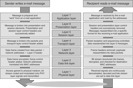
The message plus Layer 7 instructions are then passed to the part of sender’s operating system that deals with Layer 6 presentation tasks. These include the translation of data between application layer formats as well as some types of security such as secure sockets layer (SSL) encryption. This process continues down through the successive software layers, with the message gathering additional instructions or control elements at each level.
By Layer 3—the Network layer—the message will be broken down into a sequence of data packets, each carrying a source and destination IP address. At the data-link layer, the IP address is “resolved” to determine the physical address of the first device that the sending computer needs to transmit frames to—the so-called MAC or media access control address. In this example, this device may be a network switch that the sending computer is connected to or the default gateway to the Internet from the sending computer’s LAN. At the physical layer, also called the PHY layer, the data packets are encoded and modulated onto the carrier medium—a twisted wire pair in the case of a wired network, or electromagnetic radiation in the case of a wireless network—and transmitted to the device with the MAC address resolved at Layer 2.
Transmission of the message across the Internet is achieved through a number of device-to-device hops involving the PHY and data link layers of each routing or relaying device in the chain. At each step, the data link layer of the receiving device determines the MAC address of the next immediate destination, and the PHY layer transmits the packet to the device with that MAC address.
On arrival at the receiving computer, the PHY layer will demodulate and decode the voltages and frequencies detected from the transmission medium, and pass the received data stream up to the data link layer. Here the MAC and LLC elements, such as a message integrity check, will be extracted from the data stream and executed, and the message plus instructions passed up the protocol stack. At Layer 4, a protocol such as Transport Control Protocol (TCP), will ensure that all data frames making up the message have been received and will provide error recovery if any frames have gone missing. Finally the e-mail application will receive the decoded ASCII characters that make up the original transmitted message.
Standards for many layers of the OSI model have been produced by various organizations such as the Institute of Electrical and Electronics Engineers (IEEE). Each standard details the services that are provided within the relevant layer and the protocols or rules that must be followed to enable devices or other layers to call on those services. In fact, multiple standards are often developed for each layer, and they either compete until one emerges as the industry “standard” or else they peacefully coexist in niche areas.
The logical architecture of a wireless network is determined principally by standards that cover the data link (LLC plus MAC) and PHY layers of the OSI model. The following sections will give a preliminary introduction to these standards and protocols, while more detailed descriptions will be found in Parts III to V where local area (LAN), personal area (PAN) and metropolitan area (MAN) wireless networking technologies are described, respectively.
The next section starts this introductory sketch one layer higher—at the Network layer—not because this layer is specific to wireless networking, but because of the fundamental importance of its addressing and routing functions and of the underlying Internet Protocol (IP).
2.2. Network Layer Technologies
The Internet protocol (IP) is responsible for addressing and routing each data packet within a session or connection set up under the control of transport layer protocols such as TCP or UDP. The heart of the Internet Protocol is the IP address, a 32-bit number that is attached to each data packet and is used by routing software in the network or Internet to establish the source and destination of each packet.
While IP addresses, which are defined at the Network layer, link the billions of devices connected to the Internet into a single virtual network, the actual transmission of data frames between devices relies on the MAC addresses of the network interface cards (NICs), rather than the logical IP addresses of each NIC’s host device. Translation between the Layer 3 IP address and the Layer 2 MAC address is achieved using Address Resolution Protocol (ARP), which is described in Section 2.2.4.
2.2.1. IP Addressing
The 32-bit IP address is usually presented in “dot decimal” format as a series of four decimal numbers between 0 and 255; for example, 200.100.50.10. This could be expanded in full binary format as 11001000.01100100.00110010.00001010.
As well as identifying a computer or other networked device, the IP address also uniquely identifies the network that the device is connected to. These two parts of the IP address are known as the host ID and the network ID. The network ID is important because it allows a device transmitting a data packet to know what the first port of call needs to be in the route to the packet’s destination.
If a device determines that the network ID of the packet’s destination is the same as its own network ID, then the packet does not need to be externally routed, for example through the network’s gateway and out onto the Internet. The destination device is on its own network and is said to be “local” (Table 2.2). On the other hand, if the destination network ID is different from its own, the destination is a remote IP address and the packet will need to be routed onto the Internet or via some other network bridge to reach its destination. The first stage in this will be to address the packet to the network’s gateway.
Table 2.2. Local and remote IP addresses
| Sending Device | ||
| IP Address:Subnet Mask:Network ID: | 200.100.50.10255.255.255.240200.100.50.000 | 11001000.01100100.00110010.0000101011111111.11111111.11111111.11110000__________________________________11001000.01100100.00110010.00000000 |
| Local IP address | ||
| IP Address:Subnet Mask:Network ID: | 200.100.50.14255.255.255.240200.100.50.000 | 11001000.01100100.00110010.0000111011111111.11111111.11111111.11110000__________________________________11001000.01100100.00110010.00000000 |
| Remote IP address | ||
| IP Address:Subnet Mask:Network ID: | 200.100.50.18255.255.255.240200.100.50.016 | 11001000.01100100.00110010.0001001011111111.11111111.11111111.11110000__________________________________11001000.01100100.00110010.00010000 |
This process uses two more 32-bit numbers, the “subnet mask” and the “default gateway.” A device determines the network ID for a data packet destination by doing a “logical AND” operation on the packet’s destination IP address and its own subnet mask. The device determines its own network ID by doing the same operation using its own IP address and subnet mask.
2.2.2. Private IP Addresses
In February 1996, the Network Working Group requested industry comments on RFC 1918, which proposed three sets of so-called private IP addresses (Table 2.3) for use within networks that did not require Internet connectivity. These private addresses were intended to conserve IP address space by enabling many organizations to reuse the same sets of addresses within their private networks. In this situation it did not matter that a computer had an IP address that was not globally unique, provided that that computer did not need to communicate via the Internet.
Table 2.3. Private IP address ranges
| Class | Private address range start | Private address range end |
|---|---|---|
| A | 10.0.0.0 | 10.255.255.255 |
| B | 172.16.0.0 | 172.31.255.255 |
| C | 192.168.0.0 | 192.168.255.255 |
Subsequently, the Internet Assigned Numbers Authority (IANA) reserved addresses 169.254.0.0 to 169.254.255.255 for use in Automatic Private IP Addressing (APIPA). If a computer has its TCP/IP configured to obtain an IP address automatically from a DHCP server, but is unable to locate such a server, then the operating system will automatically assign a private IP address from within this range, enabling the computer to communicate within the private network.
2.2.3. Internet Protocol Version 6 (IPv6)
With 32 bits, a total of 232 or 4.29 billion IP addresses are possible—more than enough, one would think, for all the computers that the human population could possibly want to interconnect.
However, the famous statements that the world demand for computers would not exceed five machines, probably incorrectly attributed to Tom Watson Sr., chairman of IBM in 1943, or the statement of Ken Olsen, founder of Digital Equipment Corporation (DEC), to the 1977 World Future Society convention that “there is no reason for any individual to have a computer in his home,” remind us how difficult it is to predict the growth and diversity of computer applications and usage.
The industry is now working on IP version 6, which will give 128-bit IP addresses based on the thinking that a world population of 10 billion by 2020 will eventually be served by many more than one computer each. IPv6 will give a comfortable margin for future growth, with 3.4×1038 possible addresses—that is, 3.4×1027 for each of the 10 billion population, or 6.6×10²³ per square meter of the earth’s surface.
It seems doubtful that there will ever be a need for IPv7, although, to avoid the risk of joining the short list of famously mistaken predictions of trends in computer usage, it may be as well to add the caveat “on this planet.”
2.2.4. Address Resolution Protocol
As noted above, each PHY layer data transmission is addressed to the (Layer 2) MAC address of the network interface card of the receiving device, rather than to its (Layer 3) IP address. In order to address a data packet, the sender first needs to find the MAC address that corresponds to the immediate destination IP address and label the data packet with this MAC address. This is done using address resolution protocol (ARP).
Conceptually, the sending device broadcasts a message on the network that requests the device with a certain IP address to respond with its MAC address. The TCP/IP software operating in the destination device replies with the requested address and the packet can be addressed and passed on to the sender’s data link layer.
In practice, the sending device keeps a record of the MAC addresses of devices it has recently communicated with, so it does not need to broadcast a request each time. This ARP table or “cache” is looked at first and a broadcast request is only made if the destination IP address is not in the table. In many cases, a computer will be sending the packet to its default gateway and will find the gateway’s MAC address from its ARP table.
2.2.5. Routing
Routing is the mechanism that enables a data packet to find its way to a destination, whether that is a device in the next room or on the other side of the world.
A router compares the destination address of each data packet it receives with a table of addresses held in memory—the router table. If it finds a match in the table, it forwards the packet to the address associated with that table entry, which may be the address of another network or of a “next-hop” router that will pass the packet along towards its final destination.
If the router can’t find a match, it goes through the table again looking at just the network ID part of the address (extracted using the subnet mask as described above). If a match is found, the packet is sent to the associated address or, if not, the router looks for a default next-hop address and sends the packet there. As a final resort, if no default address is set, the router returns a “Host Unreachable” or “Network Unreachable” message to the sending IP address. When this message is received it usually means that somewhere along the line a router has failed.
What happens if, or when, this elegantly simple structure breaks down? Are there packets out there hopping forever around the Internet, passing from router to router and never finding their destination? The IP header includes a control field that prevents this from happening. The time-to-live (TTL) field is initialized by the sender to a certain value, usually 64, and reduced by one each time the packet passes through a router. When TTL get down to zero, the packet is discarded and the sender is notified using an Internet control message protocol (ICMP) “time-out” message.
2.2.5.1. Building Router Tables
The clever part of a router’s job is building its routing table. For simple networks a static table loaded from a start-up file is adequate but, more generally, dynamic routing enables tables to be built up by routers sending and receiving broadcast messages.
These can be either ICMP Router Solicitation and Router Advertisement messages which allow neighboring routers to ask, “Who’s there?” and respond, “I’m here,” or more useful RIP (Router Information Protocol) messages, in which a router periodically broadcasts its complete router table onto the network.
Other RIP and ICMP messages allow routers to discover the shortest path to an address, to update their tables if another router spots an inefficient routing and to periodically update routes in response to network availability and traffic conditions.
A major routing challenge occurs in mesh or mobile ad-hoc networks (MANETs), where the network topology may be continuously changing.
2.2.6. Network Address Translation
As described in Section 2.2.2 RFC 1918 defined three sets of private IP addresses for use within networks that do not require Internet connectivity.
However, with the proliferation of the Internet and the growing need for computers in these previously private networks to go online, the limitation of this solution to conserving IP addresses soon became apparent. How could a computer with a private IP address ever get a response from the Internet, when its IP address would not be recognized by any router out in the Internet as a valid destination? Network address translation (NAT) provides the solution to this problem.
When a computer sends a data packet to an IP address outside a private network, the gateway that connects the private network to the Internet will replace the private IP source address (192.168.0.1 in Table 2.4), by a public IP address (e.g., 205.55.55.1). The receiving server and Internet routers will recognize this as a valid destination address and route the data packet correctly. When the originating gateway receives a returning data packet it will replace the destination address in the data packet with the original private IP address of the initiating computer. This process of private to public IP address translation at the Internet gateway of a private network is known as network address translation.
Table 2.4. Example of a simple static NAT table
| Private IP address | Public IP address |
|---|---|
| 192.168.0.1 | 205.55.55.1 |
| 192.168.0.2 | 205.55.55.2 |
| 192.168.0.3 | 205.55.55.3 |
| 192.168.0.4 | 205.55.55.4 |
2.2.6.1. Static and Dynamic NAT
In practice, similar to routing, NAT can be either static or dynamic. In static NAT, every computer in a private network that requires Internet access has a public IP address assigned to it in a prescribed NAT table. In dynamic NAT, a pool of public IP addresses are available and are mapped to private addresses as required.
Needless to say, dynamic NAT is by far the most common, as it is automatic and requires no intervention or maintenance.
2.2.7. Port Address Translation
One complication arises if the private network’s gateway has only a single public IP address available to assign, or if more computers in a private network try to connect than there are IP addresses available to the gateway. This will often be the case for a small organization with a single Internet connection to an ISP. In this case, it would seem that only one computer within the private network would be able to connect to the Internet at a time. Port address translation (PAT) overcomes this limitation by mapping private IP addresses to different port numbers attached to the single public IP address.
When a computer within the private network sends a data packet to be routed to the Internet, the gateway replaces the source address with the single public IP address together with a random port number between 1024 and 65536 (Figure 2.2). When a data packet is returned with this destination address and port number, the PAT table (Table 2.5) enables the gateway to route the data packet to the originating computer in the private network.
Figure 2.2. Port address translation in practice

Table 2.5. Example of a simple PAT table
| Private IP address | Public IP address: Port |
|---|---|
| 192.168.0.1 | 129.35.78.178:2001 |
| 192.168.0.2 | 129.35.78.178:2002 |
| 192.168.0.3 | 129.35.78.178:2003 |
| 192.168.0.4 | 129.35.78.178:2004 |
2.3. Data Link Layer Technologies
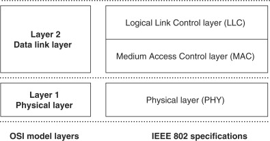
The data link layer is divided into two sub-layers—logical link control (LLC) and media access control (MAC). From the data link layer down, data packets are addressed using MAC addresses to identify the specific physical devices that are the source and destination of packets, rather than the IP addresses, URLs or domain names used by the higher OSI layers.
2.3.1. Logical Link Control
Logical link control (LLC) is the upper sub-layer of the data link layer (Figure 2.3), and is most commonly defined by the IEEE 802.2 standard. It provides an interface that enables the Network layer to work with any type of media access control layer.
Figure 2.3. OSI layers and IEEE 802.2 specifications
A frame produced by the LLC and passed down to the MAC layer is called an LLC protocol data unit (LPDU), and the LLC layer manages the transmission of LPDUs between the link layer service access points of the source and destination devices. A link layer service access point (SAP) is a port or logical connection point to a Network layer protocol (Figure 2.4). In a network supporting multiple Network layer protocols, each will have specific source SAP (SSAP) and destination SAP (DSAP) ports. The LPDU includes the 8-bit DSAP and SSAP addresses to ensure that each LPDU is passed on receipt to the correct Network layer protocol.
Figure 2.4. Logical location of LLC and MAC service access points

The LLC layer defines connectionless (Type 1) and connection oriented (Type 2) communication services and, in the latter case, the receiving LLC layer keeps track of the sequence of received LPDUs. If an LPDU is lost in transit or incorrectly received, the destination LLC requests the source to restart the transmission at the last received LPDU.
The LLC passes LPDUs down to the MAC layer at a logical connection point known as the MAC service access point (MAC SAP). The LPDU is then called a MAC service data unit (MSDU) and becomes the data payload for the MAC layer.
2.3.2. Media Access Control
The second sub-layer of the data link layer controls how and when a device is allowed to access the PHY layer to transmit data; this is the media access control or MAC layer.
In the following sections, the addressing of data packets at the MAC level is first described. This is followed by a brief look at MAC methods applied in wired networks, which provides an introduction to the more complex solutions required for media access control in wireless networks.
2.3.2.1. MAC Addressing
A receiving device needs to be able to identify those data packets transmitted on the network medium that are intended for it—this is achieved using MAC addresses. Every network adapter, whether it is an adapter for Ethernet, wireless or some other network technology, is assigned a unique serial number called its MAC address when it is manufactured.
The Ethernet address is the most common form of MAC address and consists of six bytes, usually displayed in hexadecimal, such as 00-D0-59-FE-CD-38. The first three bytes are the manufacturer's code (00-D0-59 in this case is Intel) and the remaining three are the unique serial number of the adapter. The MAC address of a network adapter on a Windows PC can be found in Windows 95, 98 or Me by clicking Start→Run, and then typing “winipcfg”, and selecting the adapter, or in Windows NT, 2000, and XP by opening a DOS Window (click Start→Programs→Accessories→Command Prompt) and typing “ipconfig/all”.
When an application such as a web browser sends a request for data onto the network, the Application layer request comes down to the MAC SAP as an MSDU. The MSDU is extended with a MAC header that includes the MAC address of the source device's network adapter. When the requested data is transmitted back onto the network, the original source address becomes the new destination address and the network adapter of the original requesting device will detect packets with its MAC address in the header, completing the round trip.
As an example, the overall structure of the IEEE 802.11 MAC frame, or MAC protocol data unit (MPDU) is shown in Figure 2.5.
Figure 2.5. MAC frame structure

The elements of the MPDU are shown in Table 2.6.
Table 2.6. Elements of the 802.11 MPDU frame structure
| MPDU element | Description |
|---|---|
| Frame control | A sequence of flags to indicate the protocol version (802.11 a/b/g), frame type (management, control, data), sub-frame type (e.g., probe request, authentication, association request, etc.), fragmentation, retries, encryption, etc. |
| Duration | Expected duration of this transmission. Used by waiting stations to estimate when the medium will again be idle. |
| Address 1 to Address 4 | Destination and source, plus optional to and from addresses within the distribution system. |
| Sequence | Sequence number to identify frame fragments or duplicates. |
| Data | The data payload passed down as the MSDU. |
| Frame check sequence | A CRC-32 checksum to enable transmission errors to be detected. |
2.3.3. Media Access Control in Wired Networks
If two devices transmit at the same time on a network's shared medium, whether wired or wireless, the two signals will interfere and the result will be unusable to both devices. Access to the shared medium therefore needs to be actively managed to ensure that the available bandwidth is not wasted through repeated collisions of this type. This is the main task of the MAC layer.
2.3.3.1. Carrier Sense Multiple Access/Collision Detection (CSMA/CD)
The most commonly used MAC method to control device transmission, and the one specified for Ethernet based networks, is carrier sense multiple access/collision detection (CSMA/CD) (Figure 2.6). When a device has a data frame to transmit onto a network that uses this method, it first checks the physical medium (carrier sensing) to see if any other device is already transmitting. If the device senses another transmitting device it waits until the transmission has finished. As soon as the carrier is free, it begins to transmit data, while at the same time continuing to listen for other transmissions.
Figure 2.6. Ethernet CSMA/CD timing

If it detects another device transmitting at the same time (collision detection), it stops transmitting and sends a short jam signal to tell other devices that a collision has occurred. Each of the devices that were trying to transmit then computes a random back-off period within a range 0 to tmax, and tries to transmit again when this period has expired. The device that by chance waits the shortest time will be the next to gain access to the medium, and the other devices will sense this transmission and go back into carrier sensing mode.
A very busy medium may result in a device experiencing repeated collisions. When this happens tmax is doubled for each new attempt, up to a maximum of 10 doublings, and if the transmission is unsuccessful after 16 attempts the frame is dropped and the device reports an “excessive collision error.”
2.3.3.2. Other Wired Network MAC Methods
Another common form of media access control for wired networks, defined by the IEEE 802.5 standard, involves passing an electronic “token” between devices on the network in a pre-defined sequence. The token is similar to a baton in a relay race in that a device can only transmit when it has captured the token.
If a device does not need control of the media to transmit data it passes the token on immediately to the next device in the sequence, while if it does have data to transmit it can do so once it receives the token. A device can only keep the token and continue to use the media for a specific period of time, after which it has to pass the token on to the next device in the sequence.
2.3.4. Media Access Control in Wireless Networks
The collision detection part of CSMA/CD is only possible if the PHY layer transceiver enables the device to listen to the medium while transmitting. This is possible on a wired network, where invalid voltages resulting from collisions can be detected, but is not possible for a radio transceiver since the transmitted signal would overload any attempt to receive at the same time. In wireless networks such as 802.11, where collision detection is not possible, a variant of CSMA/CD known as CSMA/CA is used, where the CA stands for collision avoidance.
Apart from the fact that collisions are not detected by the transmitting device, CSMA/CA has some similarities with CSMA/CD. Devices sense the medium before transmitting and wait if the medium is busy. The duration field in each transmitted frame (see preceding Table 2.6) enables a waiting device to predict how long the medium will be busy.
Once the medium is sensed as being idle, waiting devices compute a random time period, called the contention period, and attempt to transmit after the contention period has expired. This is a similar mechanism to the back off in CSMA/CD, except that here it is designed to avoid collisions between stations that are waiting for the end of another station's transmitted frame rather than being a mechanism to recover after a detected collision.
2.4. Physical Layer Technologies
When the MPDU is passed down to the PHY layer, it is processed by the PHY Layer Convergence Procedure (PLCP) and receives a preamble and header, which depend on the specific type of PHY layer in use. The PLCP preamble contains a string of bits that enables a receiver to synchronize its demodulator to the incoming signal timing.
The preamble is terminated by a specific bit sequence that identifies the start of the header, which in turn informs the receiver of the type of modulation and coding scheme to be used to decode the upcoming data unit.
The assembled PLCP protocol data unit (PPDU) is passed to the physical medium dependent (PMD) sub-layer, which transmits the PPDU over the physical medium, whether that is twisted-pair, fiber-optic cable, infrared or radio.
PHY layer technologies determine the maximum data rate that a network can achieve, since this layer defines the way the data stream is coded onto the physical transmission medium. However, the MAC and PLCP headers, preambles and error checks, together with the idle periods associated with collision avoidance or back off, mean that the PMD layer actually transmits many more bits than are passed down to the MAC SAP by the data link layer.
The next sections look at some of the PHY layer technologies applied in wired networks and briefly introduce the key features of wireless PHY technologies.
2.4.1. Physical Layer Technologies—Wired Networks
Most networks that use wireless technology will also have some associated wired networking elements, perhaps an Ethernet link to a wireless access point, a device-to-device FireWire or USB connection, or an ISDN based Internet connection. Some of the most common wired PHY layer technologies are described in this section, as a precursor to the more detailed discussion of local, personal and metropolitan area wireless network PHY layer technologies provided later.
2.4.1.1. Ethernet (IEEE 802.3)
The first of these, Ethernet, is a data link layer LAN technology first developed by Xerox and defined by the IEEE 802.3 standard. Ethernet uses carrier sense multiple access with collision detection (CSMA/CD), described above, as the media access control method.
Ethernet variants are known as “A”Base-”B” networks, where “A” stands for the speed in Mbps and “B” identifies the type of physical medium used. 10 Base-T is the standard Ethernet, running at 10 Mbps and using an unshielded twisted-pair copper wire (UTP), with a maximum distance of 500 meters between a device and the nearest hub or repeater.
The constant demand for increasing network speed has meant that faster varieties of Ethernet have been progressively developed. 100 Base-T, or Fast Ethernet operates at 100 Mbps and is compatible with 10 Base-T standard Ethernet as it uses the same twisted-pair cabling and CSMA/CD method. The trade-off is with distance between repeaters, a maximum of 205 meters being achievable for 100 Base-T. Fast Ethernet can also use other types of wiring—100 Base-TX, which is a higher-grade twisted-pair, or 100 Base-FX, which is a two strand fiber-optic cable. Faster speeds to 1 Gbps or 10 Gbps are also available.
The PMD sub-layer is specified separately from the Ethernet standard, and for UTP cabling this is based on the twisted pair-physical medium dependent (TP-PMD) specification developed by the ANSI X3T9.5 committee.
The same frame formats and CSMA/CD technology are used in 100 Base-T as in standard 10 Base-T Ethernet, and the 10-fold increase in speed is achieved by increasing the clock speed from 10 MHz to 125 MHz, and reducing the interval between transmitted frames, known as the Inter-Packet Gap (IPG), from 9.6 ms to 0.96 ms. A 125-MHz clock speed is required to deliver a 100 Mbps effective data rate because of the 4B/5B encoding described below.
To overcome the inherent low-pass nature of the UTP physical medium, and to ensure that the level of RF emissions above 30 MHz comply with FCC regulations, the 100 Base-T data encoding scheme was designed to bring the peak power in the transmitted data signal down to 31.25 MHz (close to the FCC limit) and to reduce the power in high frequency harmonics at 62.5 MHz, 125 MHz and above.
4B/5B encoding is the first step in the encoding scheme (Figure 2.7). Each 4-bit nibble of input data has a 5th bit added to ensure there are sufficient transitions in the transmitted bit stream to allow the receiver to synchronize for reliable decoding. In the second step an 11-bit feedback shift register (FSR) produces a repeating pseudo-random bit pattern which is XOR'd with the 4B/5B output data stream. The effect of this pseudo-randomization is to minimize high frequency harmonics in the final transmitted data signal. The same pseudo-random bit stream is used to recover the input data in a second XOR operation at the receiver.
Figure 2.7. 100 Base-T Ethernet data encoding scheme

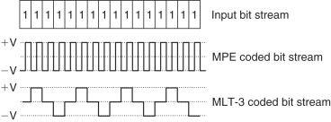
The final step uses an encoding method called Multi-Level Transition 3 (MLT-3) to shape the transmitted waveform in such a way that the center frequency of the signal is reduced from 125 MHz to 31.25 MHz.
MLT-3 is based on the repeating pattern 1, 0, −1, 0. As shown in Figure 2.8, an input 1-bit causes the output to transition to the next bit in the pattern while an input 0-bit causes no transition, i.e., the output level remaining unchanged. Compared to the Manchester Phase Encoding (MPE) scheme used in 10 Base-T Ethernet, the cycle length of the output signal is reduced by a factor of 4, giving a signal peak at 31.25 MHz instead of 125 MHz. On the physical UTP medium, the 1, 0 and −1 signal levels are represented by line voltages of +0.85, 0.0 and −0.85 volts.
Figure 2.8. Ethernet MPE and fast Ethernet MLT-3 encoding
2.4.1.2. ISDN
ISDN, which stands for Integrated Services Digital Network, allows voice and data to be transmitted simultaneously over a single pair of telephone wires. Early analog phone networks were inefficient and error prone as a long distance data communication medium and, since the 1960s, have gradually been replaced by packet-based digital switching systems.
The International Telephone and Telegraph Consultative Committee (CCITT), the predecessor of the International Telecommunications Union (ITU), issued initial guidelines for implementing ISDN in 1984, in CCITT Recommendation I.120. However, industry-wide efforts to establish a specific implementation for ISDN only started in the early 1990s when US industry members agreed to create the National ISDN 1 standard (NI-1). This standard, later superseded by National ISDN 2 (NI-2), ensured the interoperability of end user and exchange equipment.
Two basic types of ISDN service are defined—basic rate interface (BRI) and primary rate interface (PRI). ISDN carries voice and user data streams on “bearer” (B) channels, typically occupying a bandwidth of 64 kbps, and control data streams on “demand” (D) channels, with a 16 kbps or 64 kbps bandwidth depending on the service type.
BRI provides two 64 kbps B channels, which can be used to make two simultaneous voice or data connections or can be combined into one 128 kbps connection. While the B channels carry voice and user data transmission, the D channel is used to carry Data Link and Network layer control information.
The higher capacity PRI service provides 23 B channels plus one 64 kbps D channel in the US and Japan, or 30 B channels plus one D channel in Europe. As for BRI, the B channels can be combined to give data bandwidths of 1472 kbps (US) or 1920 kbps (Europe).
As noted above, telephone wires are not ideal as a digital communication medium. The ISDN PHY layer limits the effect of line attenuation, near-end and far-end crosstalk and noise by using pulse amplitude modulation (PAM) technology to achieve a high data rate at a reduced transmission rate on the line.
This is achieved by converting multiple (often two or four) binary bits into a single multilevel transmitted symbol. In the US, the 2B1Q method is used, which converts two binary bits (2B) into a single output symbol, known as a “quat” (1Q), which can have one of four values (Figure 2.9 and Table 2.7). This effectively halves the transmission rate on the line, so that a 64 kbps data rate can be transmitted at a symbol rate of 32 ksps, achieving higher data rates within the limited bandwidth of the telephone system.
Figure 2.9. 2B1Q line code using in ISDN
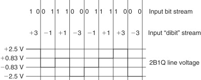
Table 2.7. 2B1Q line code used in ISDN
| Input “DIBIT” | Output “QUAT” | Line voltage |
|---|---|---|
| 10 | +3 | +2.5 |
| 11 | +1 | +.833 |
| 00 | −1 | −.833 |
| 01 | −3 | −2.5 |
As well as defining a specific PHY layer, ISDN also specifies Data Link and Network layer operation. LAP-D (link access protocol D-channel) is a Data Link protocol, defined in ITU-T Q.920/921, which ensures error free transmission on the PHY layer. Two Network layer protocols are defined in ITU-T Q.930 and ITU-T Q.931 to establish, maintain and terminate user-to-user, circuit-switched, and packet-switched network connections.
2.4.1.3. FireWire
FireWire, also known as IEEE 1394 or i.Link, was developed by Apple Computer Inc. in the mid-1990s as a local area networking technology. At that time it provided a 100 Mbps data rate, well above the Universal Serial Bus (USB) speed of 12 Mbps, and it was soon taken up by a number of companies for applications such as connecting storage and optical drives.
FireWire is now supported by many electronics and computer companies, often under the IEEE 1394 banner, because of its ability to reliably and inexpensively transmit digital video data at high speeds, over single cable lengths of up to 4.5 meters. The standard data rate is 400 Mbps, although a faster version is also available delivering 800 Mbps and with plans for 3.2 Gbps. Range can be extended up to 72 meters using signal repeaters in a 16-link daisy chain, and FireWire to fiber transceivers are also available that replace the copper cable by optical fiber and can extend range to 40 km. A generic FireWire topology is shown in Figure 2.10.
Figure 2.10. FireWire network topology: daisy-chain and tree structures
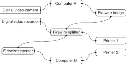
The FireWire standard defines a serial input/output port and bus, a 4 or 6 wire dual-shielded copper cable that can carry both data and power, and the related Data Link, Network and Transport layer protocols. FireWire is based on the control and status register management (CSR) architecture, which means that all interconnected devices appear as a single memory of up to 256 Terabytes (256×1012 bytes). Each transmitted packet of data contains three elements: a 10-bit bus ID that is used to determine which FireWire bus the data packet originated from, a 6-bit ID that identifies which device or node on that bus sent the data packet, and a 48-bit offset that is used to address registers and memory in a node.
While primarily used for inter-device communication, The Internet Society has combined IP with the FireWire standard to produce a standard called IP over IEEE 1394, or IP 1394. This makes it possible for networking services such as FTP, HTTP and TCP/IP to run on the high speed FireWire PHY layer as an alternative to Ethernet.
An important feature of FireWire is that the connections are “hot-swappable”, which means that a new device can be connected, or an existing device disconnected, while the connection is live. Devices are automatically assigned node IDs, and these IDs can change as the network topology changes. Combining the node ID variability of FireWire with the IP requirement for stable IP addresses of connected devices, presents one of the interesting problems in enabling IP connections over FireWire. This is solved using a special Address Resolution Protocol (ARP) called 1394 ARP.
In order to uniquely identify a device in the network, 1394 ARP uses the 64-bit Extended Unique Identifier (EUI-64), a unique 64-bit number that is assigned to every FireWire device on manufacture. This is an extended version of the MAC address that is used to address devices other than network interfaces. A 48-bit MAC address can be converted into a 64-bit EUI-64 by prefixing the two hexadecimal octets “FF-FF”.
2.4.1.4. Universal Serial Bus
The Universal Serial Bus (USB) was introduced in the mid-1990s to provide a hot-swappable “plug-and-play” interface that would replace different types of peripheral interfaces (parallel ports, serial ports, PS/2, MIDI, etc.) for devices such as joysticks, scanners, keyboards and printers. The maximum bandwidth of USB 1.0 was 12 Mbps, but this has since increased to a FireWire matching 480 Mbps with USB 2.0.
USB uses a host-centric architecture, with a host controller dealing with the identification and configuration of devices connected either directly to the host or to intermediate hubs (Figure 2.11). The USB specification supports both isochronous and asynchronous transfer types over the same connection. Isochronous transfers require guaranteed bandwidth and low latency for applications such as telephony and media streaming, while asynchronous transfers are delay-tolerant and are able to wait for available bandwidth. USB control protocols are designed specifically to give a low protocol overhead, resulting in highly effective utilization of the available bandwidth.
Figure 2.11. USB network topology: daisy-chain and tree structures

This available bandwidth is shared among all connected devices and is allocated using “pipes,” with each pipe representing a connection between the host and a single device. The bandwidth for a pipe is allocated when the pipe is established, and a wide range of different device bit rates and device types can be supported concurrently. For example, digital telephony devices can be concurrently accommodated ranging from 1 “bearer” plus 1 “demand” channel (64 kbps—see ISDN above) up to T1 capacity (1.544 Mbps).
USB employs NRZI (non return to zero inverted) as a data encoding scheme. In NRZI encoding, a 1-bit is represented by no change in output voltage level and a 0-bit is represented by a change in voltage level (Figure 2.12). A string of 0-bits therefore causes the NRZI output to toggle between states on each bit cycle, while a string of 1-bits causes a period with no transitions in the output.
Figure 2.12. USB NRZI data encoding scheme

NRZI has the advantage of a somewhat improved noise immunity compared with the straight encoding of the input data stream as output voltages.
2.4.2. Physical Layer Technologies—Wireless Networks
The PHY layer technologies that provide the Layer 1 foundation for wireless networks will be described further in Parts III, IV and V, where LAN, PAN and MAN technologies and their implementations will be covered in detail.
Each wireless PHY technology, from Bluetooth to ZigBee, will be described in terms of a number of key aspects, as summarized in Table 2.8.
Table 2.8. Aspects of PHY and data link layer wireless technologies
| Technology aspect | Issues and considerations |
|---|---|
| Spectrum | What part of the electromagnetic spectrum is used, what is the overall bandwidth available, how is this segmented into channels? What mechanisms are available to control utilized bandwidth to ensure coexistence with other users of the same spectrum? |
| Propagation | What power levels are permitted by regulatory authorities in the spectrum in question? What mechanisms are available to control the transmitted power or propagation pattern to minimize co-channel interference for other users, maximize effective range or utilize spatial diversity to increase throughput? |
| Modulation | How is encoded data carried on the physical medium, for example by modulating one or more carriers in phase and/or amplitude, or by modulating pulses in amplitude and/or position? |
| Data encoding | How are the raw bits of a data frame coded into symbols for transmission? What functions do these coding mechanisms serve, for example increasing robustness to noise or increasing the efficient use of available bandwidth? |
| Media access | How is access to the transmission medium controlled to ensure that the bandwidth available for data transmission is maximized and that contention between users is efficiently resolved? What mechanisms are available to differentiate media access for users with differing service requirements? |
The range and significance of the issues vary depending on the type of technology (Ir, RF, Near-field) and its application (PAN, LAN or WAN).
2.5. Operating System Considerations
In order to support networking, an operating system needs as a minimum to implement networking protocols, such as TCP/IP, and the device drivers required for network hardware. Early PC operating systems, including Windows versions prior to Windows 95, were not designed to support networking. However, with the rise of the Internet and other networking technologies, virtually every operating system today qualifies as a network operating system (NOS).
Individual network operating systems offer additional networking features such as firewalls, simplified set-up and diagnostic tools, remote access, and inter-connection with networks running other operating systems, as well as support for network administration tasks such as enforcing common settings for groups of users.
The choice of a network operating system will not be covered in detail here, but should be based on a similar process to that for selecting WLAN and WPAN technologies. Start by determining networking service requirements such as security, file sharing, printing and messaging. The two main network operating systems are the Microsoft Windows and Novell NetWare suites of products. A key differentiator between these two products may be a requirement for interoperability support in networks that include other operating systems such as UNIX or Linux. NetWare is often the preferred NOS in mixed operating-system networks, while simplicity of installation and administration makes Windows the preferred product suite in small networks where technical support may be limited.
2.6. Summary
The OSI network model provides the conceptual framework to describe the logical operation of all types of networks, from a wireless PAN link between a mobile phone and headset to the global operation of the Internet.
The key features that distinguish different networking technologies, particularly wired and wireless, are defined at the Data Link (LLC and MAC) and physical (PHY) layers.