Chapter 17. Security in Traditional Wireless Networks
17.1. Security in First Generation TWNs
Earlier, we discussed the Advanced Mobile Phone System (AMPS) as an example of a first-generation traditional wireless network (TWN). These networks were designed with very little security.[1] Since the AMPS radio interface was analog and since AMPS used no encryption, it was relatively simple for a radio hobbyist to intercept cellular telephone conversations with a police scanner. In the AMPS network, for the purposes of authenticating itself to the network, the mobile station sends the Electronic Serial Number (ESN) that it stores to the network. The network verifies that this is a valid ESN and then allows the subscriber access to network services. The problem with the authentication process is that the ESN is sent in clear over the air interface (obviously, since there is no encryption). This means that a radio hobbyist can not only eavesdrop on cellular telephone conversations but can also capture a valid ESN and then use it to commit cellular telephone fraud by cloning another cellular phone and making calls with it. It was the cellular fraud attack along with the concern for subscriber confidentiality that prompted cellular service providers to demand a higher level of security while designing second generation TWNs.
1 To be fair to AMPS designers, they had too many other problems before security became a priority.
17.2. Security in Second Generation TWNs
One of the prominent design decisions of second generation TWNs was the move from an analog system to use of a digital system. This design decision led to a significant improvement in the security of the system. The use of a speech coding algorithm, Gaussian Minimum Shift Keying (GMSK), digital modulation, slow frequency hopping and TDMA made casual eavesdropping by radio hobbyists significantly more difficult since it required use of much more highly specialized and expensive equipment than a simple police scanner. However, the use of a digital system is only one of the many security provisions that were designed into the second generation TWNs. In this section, we look at security in GSM networks.
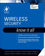
Figure 17.1 shows the high level architecture of GSM, which is the most widely deployed TWN in the world today. Before dwelling on the security of the GSM network, we need to understand the service model of GSM networks. Recall from our earlier discussion of TWNs that TWNs evolved from the PSTN with the aim of extending voice communication services to mobile subscribers. Not surprisingly therefore, the GSM network designers aimed to make the GSM “as secure as the PSTN.” To appreciate what this means, realize that the PSTN is an extremely controlled environment. The core PSTN network is controlled and regulated by a small group of operators worldwide. For most part the security in the PSTN is ensured by restricting physical access to the network. This is true both at the access network level and at the core network level.
Figure 17.1. GSM architecture
Since the GSM standard evolved from the PSTN, it carries forward the security philosophy of the PSTN. The network beyond the BTS is considered a controlled environment, since access to this part of the network is controlled by the service provider. It is only the access network (connecting the ME/MS to the BTS) that is considered a hostile operating environment. GSM security therefore aims to secure this part of the network. We look at the details of securing the access network in GSM in the next few sections.
17.2.1. Anonymity in GSM
One of the first things that a ME has to do when it switches on (or roams into) in a coverage area is to identify itself to the network requesting services from the network. Recall from our earlier discussion that the IMSI is the unique number, contained in the SIM, by which a subscriber is identified by the network for call signaling purposes. In other words, TWNs use the IMSI to route calls. It is therefore imperative for the network to know where each IMSI is at all times. This functionality wherein the network keeps track of where each IMSI (subscriber) is at any given time is known as location management. Even though the details of this topic are beyond the scope of this book, the basic underlying concept of location management is that each time the subscriber crosses a cell boundary,[2] the ME should inform the network about the IMSI’s new location. This allows the network to route an incoming call to the correct cell.
2 To be precise, a set of adjoining cells are grouped together to form a location area and the location updates are required only when the subscriber crosses a location area boundary. This reduces the number of messages and thus saves bandwidth.
In summary, the location update messages from the ME to the network need to carry the identity of the subscriber so that the network knows where to route an incoming call to at any given time. Combine this with the fact that the one-to-one mapping between the IMSI (telephone number) and the subscriber identity is publicly available. This means that if an eavesdropper can capture the IMSI over the air, they can determine the identity of the subscriber and their location. In simpler terms, this means that if you are using a cell phone anywhere in the world, your geographical location can be easily determined. This is not acceptable to most subscribers and therefore this “property” is treated as a security threat in TWNs.
The anonymity feature was designed to protect the subscriber against someone who knows the subscriber’s IMSI from using this information to trace the location of the subscriber or to identify calls made to or from the subscriber by eavesdropping on the air interface. GSM protects against subscriber traceability by using temporary mobile subscriber identity (TMSI). Unlike the IMSI which is globally unique, the TMSI has only local significance; that is, the IMSI-TMSI mapping is maintained in the VLR/MSC. When a SIM has authenticated with the network, the network allocates a TMSI to the subscriber. For all communication with the SIM, the network uses this TMSI to refer to the SIM. The use of a TMSI reduces the exposure of IMSI over the air interface to a minimum thus minimizing the probability that an eavesdropper may be able to identify and locate a subscriber.
17.2.2. Key Establishment in GSM
Once the subscriber has identified itself into the network, the next step is to prove to the network that the ME is actually who they are claiming to be: this is the authentication process. We discuss the authentication process used in GSM networks in the next section. Before we go into that discussion it is important to talk about the key establishment procedure used in GSM networks. A key establishment procedure is used to establish some sort of a secret or key between two communicating parties. This shared secret then forms the basis for securing the network.
The GSM security model uses a 128-bit preshared secret key (Ki) for securing the ME-to-BTS interface. In other words, there is no key establishment protocol in the GSM security architecture model. Instead each SIM is burnt or embedded with a unique Ki; that is, each subscriber has a unique Ki. Since this is a “shared” secret between the subscriber and the network, it is obvious that the key has to be stored somewhere in the network too. This “somewhere” is the authentication center (AuC) which is basically a database which stores the Ki of all subscribers.[3] It is this shared secret (Ki) between the SIM and the AuC that forms the basis for securing the access interface in GSM networks.
3 In reality, each service provider maintains its own AuC.
17.2.3. Authentication in GSM
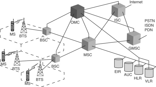
When a ME first switches on, it searches for a wireless network to connect to by listening to a certain set of frequencies. When it finds a wireless network to connect to, the ME-SIM sends a sign-on message to the BTS requesting access to the network. The BTS then contacts the mobile switching center (MSC) to decide whether or not to allow the ME-SIM access to the network. In order to make this decision, the MSC asks the home location register (HLR) to provide it with five sets of security triplets. A security triplet consists of three numbers: RAND (a 128-bit random number), SRES (a 32-bit signed response to the RAND generated using the preshared Ki) and a session key Kc (an encryption key generated using Ki). The HLR supplies these triplets to the MSC by using the Ki from the AuC. The MSC then picks one of these five sets of triplets to use for the current “session.” The RAND from this triplet is then sent to the ME (via the base station controller (BSC) and the BTS) as a challenge. The ME-SIM is then expected to generate a SRES to this RAND using the A3 algorithm and the Ki stored in its SIM (as shown in Figure 17.3). This SRES is sent back to the MSC (via the BTS and the BSC). The MSC compares the SRES received from the ME to the SRES contained in the triplet it received from the HLR. If the two match, the MSC can safely deduce that the ME has a SIM which contains a valid Ki. The MSC can therefore safely allow the ME access to the network. On the other hand, if the two SRESs do not match, the MSC would not allow the ME access to the network. The GSM authentication process is shown in Figure 17.2.
Figure 17.2. GSM authentication

As shown in Figure 17.2, the authentication process is carried out between the SIM and the MSC. The SIM uses the preshared secret Ki that it stores and carries out the A3 and the A8 algorithms to generate the SRES and the session key Kc. It is important to note that the Ki, IMSI and the A3 and A8 algorithms are stored and implemented in the SIM. More importantly, the Ki (which forms the basis of all security in GSM networks) never leaves the SIM.[4]
4 Compare this with first generation TWNs where the ESN was transmitted in clear over the air interface.
In the authentication process just described, note the inherent trust relationship between the HLR and the MSC. Such an inherent trust relationship is also present between the BSC and the MSC and again between the BSC and the BTS. This brings us to a very important characteristic of the GSM security model: it aims to secure the wireless part of the GSM network only. In retrospect, this may be considered a .aw, but remember that the GSM network evolved from the PSTN network and the aim of the GSM security designers was to make the GSM network as secure as the PSTN network. Realize that access to the PSTN network was (and still is) very tightly controlled. There are only a very small number of PSTN service providers and therefore getting access to the core network is not trivial. In other words, the core PSTN network is secured by restricting physical access to the network.[5] The GSM network designers carried forward this philosophy. The core network in the GSM architecture refers to the network beyond the BSC and it is considered “secure” since it is controlled by the service provider and access to it is tightly controlled. Therefore, the aim of the GSM security designers was to secure the wireless access network only. However, there is a missing link even if we assume that the core GSM network is secured by the service provider (either by restricting physical access to the network or by other proprietary means). This missing the link is the one between the BTS and the BSC. Remember that this link is not part of the core network. Combine this with the fact that GSM does not specify how the BTS and the BSC need to be connected.[6] In practice, it is common for the BTS and the BSC to be connected by microwave (wireless links). GSM does not specify how to secure this link, thus making it susceptible to attacks.
5 The access network of the PSTN, on the other hand, is much easier to access as compared to the core network and therefore the PSTN security in the access network is much easier to violate.
6 GSM just specifies the interface between the BTS and the BSC.
There is another important characteristic of the GSM authentication process that is worth discussing. In GSM, the authenticating entity is the SIM and not the subscriber per se. In other words, the network authenticates the SIM card and not the subscriber of the SIM card. Remember that the authentication process relies on a preshared secret (Ki) between the SIM and the AuC. During the authentication process, the MSC validates that the SIM trying to access the network has a valid Ki. What happens if a ME is stolen and is used for making calls (and using other GSM services)?
GSM does have some countermeasures to protect against equipment theft. For one, the GSM core network maintains a database of all valid mobile equipment[7] on the network. This database is called the Equipment Identity Register (EIR). If a subscriber loses their ME, it is their responsibility to report it to the service provider. Before authenticating the ME into the network, the MSC also ensures that the ME that is trying to authenticate in to the network has not been compromised. Extrapolating this approach, a service provider may also maintain a list of compromised SIMs. When a SIM is reported stolen, the service provider marks the IMSI and the corresponding Ki[8] as compromised. If a compromised SIM tries to access the network, it is denied access.
7 Each ME in the GSM network is uniquely identified by the international mobile equipment identity (IMEI).
8 There is a one-to-one mapping between the IMSI and the Ki.
Note that when the GSM authentication process completes, it has also established a security context: the session key Kc which can then be used for providing confidentiality in the network. It is the preshared secret key (Ki) between the SIM and the AuC that forms the basis of generating the session key. GSM uses the A8 algorithm to derive a session key Kc from the preshared secret key Ki as shown in Figure 17.4.
Compare Figure 17.4 with Figure 17.3. The purpose of the A8 algorithm is to derive a 64-bit session key (Kc) given the 128-bit Ki and the 128-bit RAND. On the other hand, the purpose of the A3 algorithm is to derive a 32-bit SRES given the same two inputs (the Ki and the RAND). The important thing to note here is that A3 and A8 are not algorithms per se: they are just labels (reference names) for algorithms. In other words, a service provider is free to use any algorithm that it wishes to generate SRES from Ki and RAND. The GSM specification just uses the name A3 to reference such an algorithm. Similarly, the service provider is also free to use any algorithm that it wishes to generate Kc from Ki and the name A8 is just used by the specification to reference this algorithm. Most GSM implementations combine the A3 and A8 functionality and use a single algorithm to serve both the purposes. The COMP128 algorithm, which is the reference algorithm specified in the GSM specification, takes as input the 128-bit Ki and the 128-bit RAND and generates the 32-bit SRES and a 54-bit number. The 54-bit number is appended with 10-zeros to form the 64-bit session key: Kc. We will see in Section 17.2.3 how this session key is used for providing confidentiality.
Figure 17.3. GSM SRES generation
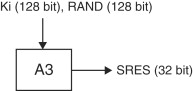
Figure 17.4. GSM Kc generation

GSM allows the service provider to choose an algorithm for A3 and A8 implementation while still ensuring seamless roaming among networks of different service providers. This is an important accomplishment and is achieved because even though the authentication process is carried out between the ME and the servicing MSC, the servicing MSC utilizes the HLR of the ME to authenticate the network. Indirectly therefore, it is the home network of the ME which authenticates the ME into another service provider’s network. Since the A3 and A8 algorithms need to execute only at the HLR and the SIM[9] (both of which “belong to” the service provider), they can be proprietary algorithms.
9 The A3 and A8 algorithms are implemented in the SIM.
One of the finer details of the authentication process in GSM is the use of five sets of security triplets that the MSC gets from the HLR. Even though only one set of triplets is required for authenticating a subscriber into the network, five sets are requested so as to improve roaming performance. Realize that a ME needs to authenticate with a MSC each time it enters its network from another service provider’s network. Instead of contacting the HLR for security triplets each time a ME roams into its coverage area, the MSC gets five sets of triplets: one for the current authentication process and four for future use. This reduces the roaming/handover time and improves system performance.
17.2.4. Confidentiality in GSM
In the previous section, we saw how the GSM authentication process establishes a security context (the session key Kc) when it completes. This session key is used for providing confidentiality over the wireless (ME – BTS) interface. The algorithm used for encrypting packets over the air interface is the A5 algorithm. Unlike A3 and A8 which are just names used by the GSM standard to reference operator-specific algorithms, the A5 is actually an encryption algorithm specified by the GSM standard. The reasoning behind this design decision is the need to support seamless roaming across networks of different service providers. As we saw in Section 17.2.3, the choice of A3 and A8 could be left to the operator since the authentication process is carried out between the SIM and the service providers HLR. The process of encryption on the other hand must necessarily be carried out between the BTS and ME without involving the home network.[10] For achieving seamless roaming between different networks, it is therefore imperative that all service providers use the same encryption algorithm.
10 A packet sent from a ME may very well reach its destination without traversing through its home network (packet routing is done by the serving MSC and not the home MSC).
The A5 algorithm is basically a stream cipher which generates a unique key stream for every packet by using the 64-bit session key (Kc) and the sequence number of the frame as the input. Since the sequence number of each packet can be easily determined, the confidentiality of the packets depends on keeping the session key (Kc) secret. There is therefore provision in GSM to change the ciphering key Kc: thus making the system more resistant to eavesdropping. The ciphering key may be changed at regular intervals or as required by the service provider.
Once the ciphering key has been established between the SIM and the network, the encryption of signaling messages and subscriber data traffic begins as soon as the GSM network sends a ciphering mode request to the ME. Note that unlike the A3 and the A8 algorithms, the encryption algorithm A5 is implemented in the ME.
17.2.5. What’s Wrong with GSM Security?
Probably the most glaring vulnerability in the GSM security architecture is that there is no provision for any integrity protection of data or messages. The GSM security architecture talks about authentication and confidentiality but not about integrity protection. The absence of integrity protection mechanisms means that the receiver cannot verify that a certain message was not tampered with. This opens the door for multiple variation of man-in-the-middle attacks in GSM networks.
Another important vulnerability in the GSM security architecture is the limited encryption scope. In simpler terms, GSM concentrates only on securing the ME-BTS interface. We saw in Section 17.2.1 that the reason behind this design decision lies in the evolution of GSM from the PSTN. The fact however remains that the only link which is cryptographically protected in the GSM network is the ME-BTS wireless interface. This exposes the rest of the network to attacks.[11] One of the most exposed links which is not cryptographically protected in the GSM network is the BTS-BSC interface. Since this link is not part of the “core” network and since this link is often a wireless link (microwave-based, satellite-based and so on), it becomes an attractive target for attacks.
11 Unless the service provider explicitly secures these links.
The GSM cipher algorithms are not published along with the GSM standards. In fact, access to these algorithms is tightly controlled. This means that the algorithms are not publicly available for peer review by the security community. This has received some criticism since one of the tenets of cryptography is that the security of the system should lie not in the algorithm but rather in the keys. The thinking is that it is therefore best to let the algorithm be publicly reviewed so that the loopholes in the algorithm are discovered and published. Workarounds can then be found to close these loopholes. However, keeping the algorithms secret (like GSM does) denies this opportunity: hence the criticism. To be fair to GSM designers, the GSM specifications came out at a time when the controls on the export and use of cryptography were extremely tight and therefore not making the algorithms public was at least partly a regulatory decision.
Even the algorithm used for encryption in the ME-BTS link is no longer secure given the increasing processing power of hardware available today. Using the simplest of all attacks, the brute force attack (which works by trying to break down the security of the system by trying each one of all possible keys), the GSM encryption algorithm A5 can be compromised within a matter of hours. The primary problem is the small key length of the session key Kc. The actual length of Kc is 64 bits. However, the last 10 bits of this key are specified to be 0 thus reducing the effective key size to 54 bits. Even though this key size is big enough to protect against real-time attacks (decrypting packets being transmitted in real-time), the state of the hardware available today makes it possible to record the packets between the MS and the BTS and then decode them at a later time. An important thing to note is that there are multiple A5 algorithms specified in the GSM standard. The first (and probably the strongest) A5 algorithm is the A5/1 algorithm. However, the A5/1 algorithm was too strong for export purposes and therefore the GSM standard specified other A5 variations which are named A5/x, for example the A5/2 algorithm has an effective security of only 216 against brute force attacks (as opposed to A5/1 which has an effective security of 254 against brute force attacks). As we know, brute-force attacks are not the most efficient attacks on the network. It is often possible to reduce the effective security of the system by exploiting loopholes in the security algorithm. For the A5 algorithm, differential cryptanalysis has been shown to reduce the effective security of the system even more. Lastly, the GSM security architecture is inflexible; in other words, it is difficult to replace the existing encryption algorithm (A5) with a more effective algorithm or to increase the length of the key used in the A5 encryption algorithm.[12] In a sense, therefore, the GSM networks are “stuck with” the A5 algorithm.
12 It is however possible to increase the effective size of the key from 54 bits to the actual length of 64 bits by removing the requirement of having the leading 10 bits of the key to be all zeros.
Another important vulnerability in the GSM security architecture is that it uses one-way authentication where the network verifies the identity of the subscriber (the ME, to be accurate). There is no way for the ME to verify the authenticity of the network. This allows a rogue element to masquerade as a BTS and hijack the ME. Again, to be fair to GSM security designers, at the time of the writing of the GSM standards, it was hard to imagine a false base station attack (an attacker masquerading as the GSM network) since the equipment required to launch such an attack was just too expensive. However, with the phenomenal growth in GSM networks, the cost of this equipment has gone down and the availability has gone up, thus making these attacks much more probable.
A very real attack against the GSM network is known as SIM cloning. The aim of this attack is to recover the Ki from a SIM card. Once the Ki is known, it can be used not only to listen to the calls made from this SIM but also to place calls which actually get billed to this subscriber. The SIM cloning attack is a chosen-plaintext attack which sends a list of chosen plaintexts to the SIM as challenges (RAND). The A8 algorithm generates the SRES to these challenges and responds back. The attacker therefore now has access to a list of chosen-plaintext, ciphertext pairs. If the algorithm used for A8 implementation is the COMP128 reference algorithm and if the RANDs are chosen appropriately, this list of pairs can be analyzed to reveal enough information to recover the Ki using differential cryptanalysis. There are many variations of the SIM cloning attack. In one approach, the attacker has physical access to the SIM card and a personal computer is used to communicate with the SIM through a smart card reader. This approach recovers the Ki in a matter of few hours.
However, it is not always possible to have physical access to the SIM. Therefore, another approach is to launch this attack wirelessly over the air interface. Even though this approach removes the requirement of having the physical access to the SIM (thus making the attack far more attractive), it introduces obstacles of its own. First, the attacker should be capable of masquerading as a rogue BTS. This means that it should be capable of generating a signal strong enough to overpower the signal of the legitimate BTS. Only if this is true would the attacker be able to communicate with the ME. One workaround is to launch this attack when the signal from the legitimate BTS is too weak (in a subway, elevator and so on) The second obstacle arises if the ME is moving. In this case there might not be enough time to collect enough chosen- plaintext, ciphertext pairs to recover the Ki because the inherent latency in the wireless interface increases the time required for each transaction. A workaround to this problem is break up the attack over a period of time. Instead of trying to get all the plaintext, ciphertext pairs in one run, the attacker gets only as many pairs as they can and stores them. They repeat this process over a period of days till they get enough data to recover the Ki.
Yet another variation of this attack attempts to have the AuC generate the SRES of given RANDs instead of using the SIM. This attack exploits the lack of security in the SS7 signaling network. Since the core signaling network is not cryptographically protected and incoming messages are not verified for authenticity, it is possible to use the AuC to generate SRESs for chosen RANDs.
A salient feature of the GSM security architecture is that it is transparent to the subscriber. However this feature sometimes becomes a loophole. There are scenarios where a service provider may choose to use null encryption (A5/0). If a ME is in such a cell, should it be allowed to connect to such a BTS or not? The current design is to allow the ME to connect to such a cell.
17.3. Security in 2.5 Generation TWNs
As we have discussed, the GSM network evolved from the PSTN network and the GSM security architecture followed the same path. GSM security architecture was designed to secure only the last hop (BTS-ME) in the network since the rest of the network was assumed to be a “secure environment” controlled and secured by the service provider. This architecture worked for voice communication and PSTN-based networks because it was relatively easy for the limited number of service providers to maintain a secure environment in the core network.
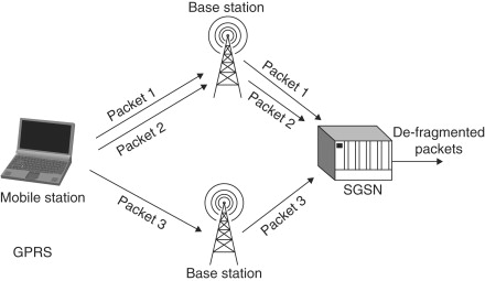
With the explosive growth in the Internet, 2G service providers upgraded their networks to 2.5G networks to provide data services to their subscribers. These data services basically consisted of connecting the ME to the Internet (that is, various web servers). The 2.5G system architecture looks like the one shown in Figure 17.5.
Figure 17.5. GPRS network architecture
General Packet Radio Service (GPRS) was basically intended to provide the ME with data-connectivity to various web servers. Since data usually requires more bandwidth than voice, the GSM network achieves this by allocating multiple timeslots to an ME which is trying to access data services.[13] This has an interesting implication on the security architecture of the network. Recall that for voice calls the encryption and decryption happens at the BTS on the network side. For the A5 algorithm, this is possible because the BTS knows the ciphering key Kc and can implicitly deduce the sequence number. These are the only two inputs required to operate the A5 algorithm. In the GPRS architecture, since a ME has multiple timeslots to transmit, it is possible that multiple timeslots are allocated on channels belonging to different BTSs to connect to the network. This may happen for example during roaming as shown in Figure 17.6. This in turn means that the BTS cannot implicitly deduce the sequence number of a packet. To solve this problem, GPRS transfers the responsibility of encryption and decryption on the network side from the BTS to the SGSN. The SGSN is the equivalent of the VLR and MSC. This means that the GPRS architecture effectively prevents (protects against) eavesdropping on the backbone between the BTS and the SGSN too.
13 Recall that for a voice call, GSM assigns only one timeslot to a ME.
Figure 17.6. GPRS roaming
17.3.1. WAP
The GPRS protocol provides a connectivity mechanism for the ME to connect to a data network (Internet). From an OSI layer perspective, GPRS provides Layer 2 (point-to-point) connectivity. What is still required is a set of higher layer protocols (see Figure 17.7). In the wired network, internet applications use the Hyper Text Transfer Protocol (HTTP) and the Hyper Text Markup Language (HTML) to access and retrieve data content (web pages, applets and so on) from web servers. Ideally, the same protocols could have been used over GPRS. This, along with an embedded browser in the ME, would have made the ME a PC-like medium to browse the internet. The problem is that we are operating in a bandwidth-constrained medium and a memory-constrained, CPU-constrained, screen-size constrained end-point (the ME). HTTP and HTML are not optimized for operating under such conditions. This is where Wireless Application Protocol (WAP) comes in.
Figure 17.7. WAP—Network architecture

WAP is an open specification that offers a standard method to access Internet-based content and services from wireless devices such as mobile phones and Personal Digital Assistants (PDAs). The WAP protocol stack is designed for minimizing bandwidth requirements and guaranteeing that a variety of wireless networks can run WAP applications. The information content meant for the ME is formatted suitably for the ME’s small screen, and a low bandwidth, high latency environment; i.e., the Wireless Application Environment (WAE).
Figure 17.8 shows the WAP programming model. The client is the embedded browser in the ME and the server may be any regular web server. The new entity in the architecture is the WAP gateway. The embedded browser connects to the WAP gateway and makes requests for information from web servers in the form of a normal universal resource locator (URL). The gateway forwards this request to the appropriate web server and gets the information using HTTP in HTML format. Note that the gateway to the web servers is usually a wired link, which is appropriate for using HTTP and HTML. The role of the gateway is to reformat the content from the web server suitable for transmission in a WAE and for display on a ME. The language used for creating this content is called Wireless Markup Language (WML) which is optimized for low bandwidth, high latency connections. To summarize, the WAP gateway is the translator between HTTP, HTML on the web server side and WTP, WML on the ME side.
Figure 17.8. WAP—Overview

So, together WAP and GPRS allow the ME to connect to the Internet. Since the Internet is a huge uncontrolled network of haphazardly connected (and growing) nodes, this breaks one of the biggest assumptions of the GSM security architecture—that the core network is a controlled secure environment. In this new operating environment, securing just the last link is not enough. Instead, an end-to-end security architecture is desired. This end-to-end security is achieved by the Wireless Transport Layer Security (WTLS) layer in the WAP stack.
WTLS is modeled along the lines of Secure Sockets Layer (SSL)/Transport Layer Security (TLS). The reason for designing a new protocol along the lines of TLS and not using TLS itself is optimization. First, TLS was designed to be used over a reliable transport layer (such as TCP) whereas WTLS needs to operate over an unreliable datagram transport where datagrams may be lost, duplicated or re-ordered. Second, the WTLS protocol was modified to cope with long roundtrip times and limited bandwidth availability typical of the wireless environment. Finally, WTLS has been optimized to operate with limited processing power and limited memory of the ME. Figure 17.9 shows a WTLS session.
Figure 17.9. TLS in WAP

17.3.2. Code Security
For most part, network security is concerned with transactional security on the network. In other words, we talk about securing the link(s) in the network using encryption, securing access to the network using authentication and so on. The merging of the GSM network with the Internet, however, adds another dimension to the concept of network security. The ME in a GPRS network can “browse” the Internet. In the Internet architecture, web servers sometimes download applets (short programs) on to the client (ME) over the network. These applets then execute at the client (ME). Consider what happens if the applet is a malicious piece of code or it simply has a bug which can harm the ME. To protect against such attacks, it is extremely important that the applets (or other programs which are downloaded from remote sites but execute on the client) be secure.
From a client’s (ME’s) perspective however, it is difficult to ensure the security of the applet by examining the source code. Therefore, most applets are signed by Certificate Authorities (CAs) (See the section on Public Key Infrastructure (PKI)). Before executing the applet, the subscriber can be informed of the CA which has signed the applet. If the subscriber trusts that CA, they can allow the applet to be executed on their ME otherwise they can block the execution of the applet.
17.4. Security in 3G TWNs
The UMTS security architecture was designed using the GSM security as the starting point. The reason behind doing so was to adopt the GSM security features that have proved to be robust and redesign the features that have been found to be weak. Another reason for doing so was to ensure interoperability between GSM and Universal Mobile Telecommunications System (UMTS) elements.
17.4.1. Anonymity in UMTS
UMTS anonymity builds on the concept of TMSI introduced by GSM (see Section 17.2.1). To avoid subscriber traceability, which may lead to the compromise of subscriber identity, the subscriber should not be identified for a long period by means of the same temporary identity. To achieve this, the UMTS architecture provides provisions for encrypting any signaling or subscriber data that might reveal the subscriber’s identity.
Note that we seemingly have a chicken and egg situation here. As we discussed in Section 17.2.1, one of the first things that the ME has to do is to identify itself (its IMSI) to the network. On the other hand, the TMSI allocation procedure (initiated by the VSC/MLR) should be performed after the initiation of ciphering to ensure that the TMSI (and hence the subscriber identity) is not vulnerable to eavesdropping. The problem is that ciphering cannot start unless the CK has been established between the UMTS Subscriber Identity Module (USIM) and the network and the CK cannot be established unless the network first identifies the subscriber using its IMSI. The problem is not as complicated as it appears though. Let’s dig a little deeper.
Recall from Section 17.2.1 that the TMSI has only local significance; in other words, the TMSI is allocated by the VLR/MSC and the IMSI-TMSI mapping is maintained in the VLR/MSC. When the subscriber roams into the coverage area of another VLR/ MSC (hereafter referred to as VLRn), it continues to identify itself with the TMSI that it was allocated by the previous VLR/MSC (hereafter referred to as VLRo). Obviously VLRn does not recognize this TMSI, since it was allocated by VLRo. In the UMTS architecture, VLRn should request VLRo to get the IMSI corresponding to this TMSI. If VLRn cannot retrieve this information from VLRo, only then should VLRn request the subscriber to identify itself by its IMSI.
The bottom line is that most times, VLRn can determine the IMSI of a subscriber without the ME actually having to transmit the IMSI over the air interface. Instead the ME can identify itself using the TMSI that is already assigned to it. The AKA procedure can then be carried out from this point on.[14] At the completion of the AKA procedure, the CK has been established between the USIM and the network and the VLR/MSC can therefore assign a new TMSI to the ME while ensuring that it is encrypted. From this point on, the TMSI can be safely used by the network and the USIM to identify the subscriber.
14 Or VLRn can decide to use a previously existing set of keys.
Besides the IMSI and the TMSI which can cause a subscriber’s identity to be compromised, there is another identity in the UMTS security architecture that can be exploited to trace a subscriber. This is the Sequence Number (SQN) which is used by the ME to authenticate the network. The reason why the SQN can also be used to identify the subscriber is that the network maintains a per-subscriber SQN which is incremented sequentially. It is therefore necessary to encrypt the SQN to protect against subscriber traceability. As explained in Section 17.4.2 the authentication process (also known as the Authentication and Key Agreement (AKA)[15] process) in UMTS establishes various keys and one of these is the anonymity key (AK). Just like the CK and IK, the AK is established or derived independently at the USIM and the VLR/MSC without ever being transmitted over the air. In other words, the AK is known only to the USIM and the VLR/MSC. The use of the AK is to protect the Sequence Number (SQN) from eavesdropping.
15 Authentication and key agreement.
17.4.2. Key Establishment in UMTS
Just like GSM, there is no key-establishment protocol in UMTS and just like GSM it uses a 128-bit preshared secret key (Ki) between the UMTS Subscriber Identity Module (USIM) and the authentication center (AuC) which forms the basis for all security in UMTS.
17.4.3. Authentication in UMTS
The authentication model in UMTS follows closely from the GSM authentication model but there is one significant difference. The authentication procedure is mutual; that is, the network authenticates the subscriber (USIM) and the subscriber (USIM) authenticates the network. This is unlike GSM where there is no provision for the subscriber to authenticate the validity of the network.
Figure 17.10a shows the authentication procedure in UMTS networks. The process starts when a subscriber (USIM) first sends a sign-on message to the base station it wants to connect to (not shown in Figure 17.10a). The base station then contacts the VLR/MSC (via the RNC) to decide whether or not to allow the USIM access to the network. In order to make this decision, the MSC asks the HLR to provide it with a set of authentication vectors. The authentication vector is the equivalent of the security triplets in GSM. The UMTS authentication vector is actually a security quintet[16] which consists of five numbers: RAND (a 128-bit random number), XRES (the 32-bit expected signed response to the RAND), CK (a 128-bit session cipher or encryption key), IK (a 128-bit integrity key) and AUTN (a 128-bit network authentication token).
16 A GSM security triplet consists of three numbers: RAND (a 128-bit random number), SRES (a 32-bit signed response to the RAND generated using the preshared Ki) and a session key Kc (an encryption key generated using Ki).
Figure 17.10a. UMTS authentication

Figure 17.10b. UMTS authentication vector generation

When the HLR receives a request for generating authentication vectors from a MSC/VLR, it first generates a random number, RAND and a sequence number, SQN. The HLR then requests the AuC to supply the preshared secret Ki corresponding to this USIM. The RAND, SQN, Ki and the Authentication Management Field (AMF) serve as the input to the five functions (f1 – f5) and generate the security quintet. We tabulate below all the relevant entities involved in the process.
RAND: Random challenge generated by AuC.
XRES: f2K(RAND): Expected subscriber RESponse as computed by AuC.
CK: f3K(RAND): Cipher Key used for encrypting data and signaling messages.
AMF: Authentication Management Field.
MAC: f1K(SQN || RAND || AMF): Message Authentication Code.
AUTN: SQN (+) AK || AMF || MAC: Network Authentication Token.
Security Quintet: (RAND, XRES, CK, IK, AUTN).
When the VLR/MSC receives the set of authentication vectors, it selects the first[17] authentication vector and stores the rest for later use. The VLR/MSC then sends the RAND and the AUTN from the selected authentication vector to the USIM. The RAND serves as a challenge. When the USIM receives these, it carries out the procedure shown in Figure 17.11.
17 Note the importance of sequence. In the GSM security architecture, the MSC/VLR selects any one of the five security triplets.
Figure 17.11. UMTS response generation at USIM

Note that the procedure shown in Figure 17.11 requires only three inputs: AUTN, RAND and Ki. The former two entities are received from the VLR/MSC and Ki is already stored in the USIM. Note also that AUTN basically consists of SQN (+) AK || AMF || MAC which are used as shown in Figure 17.11. Once the USIM has calculated all the entities, it verifies that the MAC received in the AUTN and the XMAC calculated by the USIM match. It also verifies that the SQN obtained from the network’s message is in the correct range. Once the USIM has verified these matches, the USIM has authenticated the network since a rogue network can’t generate a valid SQN[18].
18 Recall from Section 17.4.1 that the network maintains a per-subscriber SQN which is incremented sequentially each time the ME and the network carry out the authentication process. Also, this SQN can be kept secret by using the AK.
At this point, one half of the authentication process is now complete. What is now left is for the network to authenticate the USIM. To complete this process, the USIM sends back the RES to the network. Note that the RES is generated from the RAND using the preshared secret key that it stores, Ki and the function f2; i.e., RES=f2K(RAND). The RES is therefore the response to the challenge (RAND). When the VLR/MSC receives the RES from the USIM, it compares it with the XRES in the corresponding authentication vector that it received from the HLR. If the two match, the network (VLR/MSC) has successfully authenticated the USIM and allows it to access network services.
At this point, the mutual authentication process has completed and the following keys have been established between the network and the USIM: CK, IK and AK. These keys now form the basis of providing confidentiality, integrity and anonymity in the UMTS architecture.
Recall from Section 17.2.3 that GSM left the choice of the authentication protocol to the service provider. Most service providers used the COMP128 algorithm for this purpose. UMTS follows the same philosophy. It leaves the choice of the authentication protocol to the service provider but does provide an example algorithm, MILENAGE, that service providers may use.
17.4.4. Confidentiality in UMTS
The GSM encryption algorithm was A5, which used a 64-bit session key Kc. The UMTS encryption algorithm is known as KASUMI and uses a 128-bit session key CK. The KASUMI algorithm is more secure than A5 and one of the reasons for this is simply the use of longer keys for encryption. Figure 17.12 shows the encryption process used in UMTS networks.
Figure 17.12. UMTS encryption

Let’s take a look at the input values used for encryption. First there is the 128-bit ciphering key (also known as encryption key), CK which has been established at the USIM and at the VLR/MSC as a result of the authentication process. Second, there is the 32-bit COUNT-C which is a ciphering sequence number which is updated sequentially for each plaintext block. Third, there is the 5-bit BEARER which is a unique identifier for the bearer channel (the channel number which is used for carrying end-user’s traffic) in use. Fourth, there is the 1-bit DIRECTION value which indicates the direction of transmission (uplink or downlink). Finally, there is the 16-bit LENGTH which indicates the length of the key-stream block. All these values are input into the f8 encryption algorithm[19] to generate a key stream. This key stream is XORed with the plaintext block to generate the ciphertext block. At the receiving end, the same process is repeated except that the generated key stream is XORed with the received ciphertext to get back the plaintext.
19 Just like in GSM, “f8” is a label for an algorithm rather than an algorithm itself. One oft-used f8 algorithm is the Kasumi algorithm.
Besides the use of increased key lengths, there is another significant improvement in UMTS security architecture over the GSM security architecture. Recall from Section 17.2.2 that the GSM confidentiality was limited to securing the link between the ME and the BTS. This made the link between the BTS and the BSC (usually a microwave link) unsecure. The UMTS security architecture extends the encrypted interface from the BTS back to the RNC (the UMTS equivalent of BSC). Since the traffic between the USIM and RNC is encrypted, this protects not only the wireless interface between the USIM and base station but also the interface between the base station and the RNC, thus closing one of the loopholes of GSM security. One last thing to note is that the encryption in the UMTS security architecture is applied to all subscriber traffic as well as signaling messages.
17.4.5. Integrity Protection in UMTS
As we discussed in Section 17.2.5, one of the gaping loopholes in the GSM security architecture was the absence of an integrity protection mechanism. UMTS attempts to solve this problem using the integrity key IK derived using the authentication process as described in Section 17.4.2.
The UMTS integrity mechanism is shown in Figure 17.13. Let’s look at the input values required for the integrity mechanism. First, there is the 128-bit integrity key, IK, which is established as a part of the UMTS authentication process. Second, there is the 32-bit integrity sequence number which is updated sequentially for each plaintext block that is integrity protected. Third, there is the message itself which needs to be integrity protected. Fourth, there is the DIRECTION bit (uplink or downlink). Finally, there is the 32-bit FRESH which is a per-connection nonce. All these values are input to the f9 algorithm and the output is a 32-bit MAC-I (message authentication code). This MAC is attached to the message by the sender. At the receiving end, the same process is repeated to calculate the XMAC-I. The receiver then compares the computed XMAC to the received MAC, so the receiver can deduce that the message was not tampered with. Thus we have integrity protected the message. The integrity protection mechanism just described is applied to all but a specifically excluded set of signaling messages.
Figure 17.13. UMTS message integrity

Ideally, the integrity protection mechanism should be used for protecting user traffic too. However, integrity protecting each packet involves a lot of overhead in terms of processing and bandwidth, but let’s take a step back and think about it: what is it that we are trying to achieve by integrity protecting user traffic? The aim is to ensure that the information content of the voice conversation is not modified; in other words, words are not inserted, deleted or modified in the conversation. However, ensuring this does not really require that each voice packet be integrity protected, since inserting, deleting or modifying a word in a conversation (without the user realizing) would affect voice samples spanning several packets.[20] Almost invariably, inserting, deleting or modifying words in a conversation without the user realizing this, would lead to a change in the number of packets. It is therefore usually sufficient to integrity protect the number of user packets in a conversation. This is the compromise that UMTS uses. The RNC monitors the sequence numbers that are used for ciphering voice packets related to each radio bearer (channel). Periodically, the RNC may send a message containing these sequence numbers (which reflect the amount of data sent and received on each active radio bearer) to the ME. Obviously, this message itself is integrity protected. On receiving this message, the ME can verify that the value received in this message matches the counter values that the ME maintains locally. This provides integrity protection of the user traffic.
20 Voice Packets basically consist of samples of digitized voice. Typical voice calls over TWNs usually use a rate of 10–20 Kbps to digitize voice. Therefore a single spoken word would usually span several packets.
17.4.6. Putting the Pieces Together
The UMTS security architecture is huge, complex and entails a lot of features. We have seen individual pieces of this security architecture in the last few sections. In this section, we try to put all the pieces together to get a complete picture.
Figure 17.14 shows the overview of the UMTS security process. The process starts when the ME first starts the Layer 2 connection (RRC layer connection) procedure. Note that the Layer 2 connection refers to the connection between the MS and the RNC. The message exchange between the ME and the VLR/MSC is a Layer 3 level connection. In any case, as part of the RRC layer connection procedure, the MS sends, among other things, its list of security capabilities: User Encryption Algorithms (UEAs), User Integrity Algorithms (UIAs) and so on to the RNC. The RNC stores these subscriber security capabilities.
Figure 17.14. UMTS security—overview

When the ME sends its first Layer 3 Connection message to the VLR/MSC, it includes in this message the subscriber identity (either the TMSI or the IMSI) and Key Set Identifier (KSI). The KSI identifies the set of keys (CK, IK, and so on) that were last established between this ME and this CN domain.[21] Note that the first Layer 3 message can be any one of a set of possible initial Layer 3 messages (location update request, routing update request, attach request and so on). The important thing is that whichever Layer 3 is sent first,[22] it will carry the subscriber identity and the KSI.
21 Usually a service provider's domain.
22 This will depend on the context in which it is sent.
Once the VLR/MSC receives the subscriber identity and the KSI, it may decide to start a new AKA procedure or it may decide to continue using the keys that it already shares with the ME from last time. This decision is left to the VLR/MSC. In other words, the service provider is free to control when (and how frequently) it authenticates the identity of the subscriber and establishes a new key set. In either case, at this point, both the ME (the USIM to be precise) and the VLR/MSC trust each other’s identity and have agreed upon the set of keys (CK, IK) that they will use.
Note however that the security algorithms to be used have not been agreed on. This is the next step. Towards this end, the VLR/MSC sends a list of the encryption and integrity algorithms that this subscriber is allowed to use to the RNC. The RNC now has the set of UEAs and the UIAs that the ME wishes to use and also the set of encryption and integrity algorithms that the VLR/MSC wishes to use. The RNC takes the intersection of these two sets and determines an encryption and integrity algorithm that is most acceptable to the ME and the VLR/MSC. In other words, the RNC has now decided upon the encryption and the integrity algorithm that would be used between the ME and the VLR/MSC. It does however need to pass this information on to the ME and the VLR/MSC.
The RNC sends the selected algorithm information in the next message. Also included in this message is the full set of security capabilities that the MS had sent to the RNC during RRC connection establishment time. Sending the UEAs and UIAs that the RNC received from the MS back to the MS may seem redundant at first. Realize however, that this is the first message that is integrity protected; in other words, no message sent over the air interface before this message was integrity protected.[23] This means that the set of security capabilities that the MS had sent to the RNC as part of RRC connection establishment procedure was not integrity protected. Therefore, a malicious eavesdropper could have modified this message to change the set of security capabilities that the MS offers to the network thus forcing the MS and the network to use weaker encryption and integrity algorithms. Such an attack is known as the bidding down attack. To prevent against such an attack, the RNC returns the full set of security capabilities that the MS had sent to the RNC in an integrity protected message.
23 But all messages from now on are integrity protected.
On receiving this message, the MS ensures the integrity of this message by calculating the XMAC on this message and comparing it with the MAC received in the message, thus verifying that the message has not been modified by a malicious eavesdropper. Next, the MS verifies that the set of capabilities in this message is the same as the set of capabilities that the MS had sent to the RNC during the RRC connection setup. Once the MS has verified that the set of security capabilities were not modified, it sends a security mode complete message back to the RNC. Note that this and all subsequent messages from the MS are integrity protected.
At this point the MS has authenticated the network, the network has authenticated the MS and the MS has all the information (algorithms, keys and so on) that it requires to provide confidentiality and integrity protection. However, the VLR/MSC does not have all the information that it requires for this purpose since the encryption and the integrity protection algorithms to be used were determined by the RNC and never conveyed to the VLR/MSC. This is what is done next. The RNC sends a message specifying the encryption and the integrity protection algorithms to be used to the VLR/MSC. From this point on not only are all the messages integrity protected but also encrypted to provide confidentiality.
17.4.7. Network Domain Security
In the last few sections, we have seen how UMTS provides security in the access network. The term access network here refers to the connection between the ME and the VLR/MSC. As we discussed in Section 17.2, second generation TWNs were concerned only with securing the wireless access network and the core network was considered to be a secure operating environment. This security in the core network was based on the fact that the core network was accessible to only a relatively small number of well established institutions and it was therefore very difficult for an attacker to get access to this network.
However, this assumption of the core network being inherently secure is no longer valid since with the opening up of telecom regulations all over the world, the number of service providers has grown significantly. This has two important implications. One, there are a lot more institutions that now have access to the core network, thus increasing the probability that the core network may be compromised. Two, since the access networks of these service providers need to communicate with each other (to provide seamless mobility for example), there is a growing need to make this internetwork communication secure.
The ideal solution obviously would have been to secure the core network. The problem is that this was a huge task and beyond the scope of UMTS network designers. The UMTS designers therefore limited their scope to securing the mobile specific part of the network, which is known as the Mobile Application Part (MAP). To this end, UMTS specifies the MAPSEC protocol, which works at the application layer to protect MAP messages cryptographically.[24]Figure 17.15 shows how MAPSEC is used for protecting MAP messages being exchanged between two networks.
24 Some MAP messages are still sent in plaintext without any protection, to avoid performance penalties.
Figure 17.15. MAPSEC
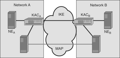
The Key Administration Center (KAC) is a new entity introduced in the system architecture by MAPSEC. Each network which wishes to use MAPSEC has a KAC. The purpose of KAC in Network A is to establish a Security Association (SA) with the KAC in Network B. The term security association refers to the set of security algorithms, keys, key lifetimes and so on that the two networks will use to secure MAP messages that they exchange. To establish a SA, the KACs use the Internet Key Exchange (IKE) protocol. Once the SAs have been established, the KAC distributes this information to its Network Elements (NE). The network elements then use these SAs to protect the MAP messages. MAPSEC allows for three modes of protection: no protection, integrity protection only and integrity with confidentiality.
As you will have noticed, the design of the MAPSEC protocol is strongly influenced by the IPSec protocol. This influence comes across in the use of IKE for key establishment and the use of SAs, among other things. There is an important reason for this. The exploding growth in data networks in the last few years has led to the convergence of voice and data networks and the boundaries between these two networks are fast disappearing. 2.5G TWNs marked the integration of data networks with TWNs. 3G networks are expected to be even more closely tied to IP-based networks. This means that replacing SS7 signaling with IP-based signaling (like SIP) is extremely likely. Therefore, the UMTS network designers provided a method not only for securing MAP in SS7 networks (MAPSEC) but also for using MAP over IP-based networks which may be protected by the already well-established IPSec protocol. Keeping this convergence in mind, the UMTS network designers tried to model MAPSEC along the IPSec lines.
Figure 17.16 shows how network domain security is achieved for IP-based control messages (out of which MAP messages may just be one type of messages being protected). Note that Figure 17.16 resembles Figure 17.15 closely. The only difference seems to be that the KAC has been replaced by another entity known as the Security Gateway (SEG). Like the KAC, the SEG in Network A establishes SAs with its peer in Network B. However, unlike the KAC, the SEG does not distribute the SAs to its network elements. Instead, it maintains a database of established SAs and a database of security policies which specify how and when the SAs are to be used. When the network elements in Network A want to send control messages (like MAP messages) to their peers in Network B, they send the message to the SEG. It is the SEG which is then responsible for protecting the message in accordance with the policy using the established SA. In other words, the SEG is responsible not only for establishing the SAs but also for using them to protect control messages.
Figure 17.16. MAP over IP-based networks

17.5. Summary
From the rudimentary ESN in first generation TWNs to the provisions for confidentiality, integration, mutual authentication, and anonymity in the UMTS networks, security in TWNs has come a long way. This improvement in security can be attributed to many factors. Probably the most important among these are the demand for security from subscribers and technological enhancements in cryptography. There is also however another important factor which has made this possible and this is Moore’s Law. Remember that security always comes at a cost. Without the significant growth in processing power per square millimeter, it would probably have been impossible to provide the kind of security that TWN subscribers have come to expect. In the near future, the convergence of TWNs with the Internet will surely bring new challenges. What is important is that we be willing to admit the loopholes and then fix them.