Day 17. SNMP and Syslog
CCNA 200-101 ICND2 Exam Topics
![]() Describe SNMP v2 and v3
Describe SNMP v2 and v3
![]() Configure and verify syslog
Configure and verify syslog
Key Topics
The review today covers one of the most useful management tools available to the network administrator: Simple Network Management Protocol (SNMP). Although you only need to be able to describe SNMP for the CCNA exam, this review also covers the basic configuration and verification commands for SNMP Version 2 (SNMPv2).
SNMP Operation
SNMP is an application layer protocol that provides a message format for communication between managers and agents.
SNMP Components
The SNMP system consists of three elements:
![]() SNMP manager
SNMP manager
![]() SNMP agents (managed node)
SNMP agents (managed node)
![]() Management Information Base (MIB)
Management Information Base (MIB)
SNMP Messages
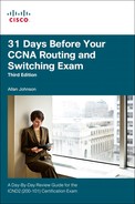
The SNMP manager is part of a network management system (NMS) and runs SNMP management software. SNMP agents are managed devices. The MIB stores SNMP variables. SNMP uses three basic messages between SNMP managers and agents. The SNMP manager uses get messages to poll a device for information and set messages to change a device parameter. An SNMP agent can independently notify the NMS when a problem occurs using SNMP traps.
For example, SNMP can monitor the CPU utilization on a Cisco router. The NMS can sample this value periodically and warn the network administrator when the value deviates from the baseline. An SNMP agent can also be configured to send a trap message when CPU utilization is driving away from normal values for the network. Table 17-1 summarizes the get and set actions.
SNMP Versions
There are several versions of SNMP, including the following:
![]() SNMPv1: The Simple Network Management Protocol defined in RFC 1157
SNMPv1: The Simple Network Management Protocol defined in RFC 1157
![]() SNMPv2c: Defined in RFCs 1901 to 1908; utilizes community-string-based Administrative Framework
SNMPv2c: Defined in RFCs 1901 to 1908; utilizes community-string-based Administrative Framework
![]() SNMPv3: Interoperable standards-based protocol originally defined in RFCs 2273 to 2275; provides secure access to devices by authenticating and encrypting packets over the network
SNMPv3: Interoperable standards-based protocol originally defined in RFCs 2273 to 2275; provides secure access to devices by authenticating and encrypting packets over the network
SNMPv1 and SNMPv2c use community strings that control access to the MIB. Community strings are plain-text passwords. There are two types of community strings:
![]() Read-only (ro): Provides access to the MIB variables, but does not allow these variables to be changed, only read
Read-only (ro): Provides access to the MIB variables, but does not allow these variables to be changed, only read
![]() Read-write (rw): Provides read and write access to all objects in the MIB
Read-write (rw): Provides read and write access to all objects in the MIB
The Management Information Base
The MIB organizes variables hierarchically. MIB variables enable the management software to monitor and control the network device. Formally, the MIB defines each variable as an object ID (OID). OIDs uniquely identify managed objects in the MIB hierarchy. The MIB organizes the OIDs based on RFC standards into a hierarchy of OIDs, usually shown as a tree.
RFCs define some common public variables. Figure 17-1 shows portions of the MIB structure defined by Cisco Systems, Inc.

Note how the OID can be described in words or numbers to help locate a particular variable in the tree. For example, OIDs belonging to Cisco are numbered as follows: iso(1). org (3).dod (6).internet (1).private (4).enterprises (1).cisco (9). This is displayed or configured as 1.3.6.1.4.1.9.
One way to demonstrate using these OIDs is to look at how they could be implemented in the freeware SNMPGET utility. Example 17-1 shows how you might configure SNMPGET to obtain a 5-minute exponential moving average of the CPU busy percentage from a router.
Example 17-1 Obtaining a MIB Value with SNMPGET
[13:22][cisco@NMS~ ]$ snmpget -v2c -c community 10.250.250.14 1.3.6.1.4.1.9.2.1.58.0
SNMPv2-SMI::enterprises.9.2.1.58.0 = INTEGER: 11
The bold text shows a rather long command with several parameters highlighted, as follows:
![]() -v2c: The version of SNMP in use
-v2c: The version of SNMP in use
![]() -c community: The SNMP password, called a community string
-c community: The SNMP password, called a community string
![]() 10.250.250.14: The IP address of the monitored device
10.250.250.14: The IP address of the monitored device
![]() 1.3.6.1.4.1.9.2.1.58.0: The numeric OID of the MIB variable
1.3.6.1.4.1.9.2.1.58.0: The numeric OID of the MIB variable
The last line shows the response. The output shows a shortened version of the MIB variable. It then lists the actual value in the MIB location, which in this example means that the CPU is at 11 percent utilization.
Configuring SNMP
Configuring SNMP Version 2c on a Cisco router or switch requires only one global configuration command: snmp-server community. The following steps include some optional commands:
Step 1 (Required) Configure the community string and access level (read-only or read-write) with the snmp-server community string {RO|RW} global command.
Step 2 (Optional) Document the location of the device using the snmp-server location text-describing-location global configuration command.
Step 3 (Optional) Document the location of the device using the snmp-server contact contact-name global configuration command.
Step 4 (Optional) Restrict SNMP access to NMS hosts that are permitted by an access control list (ACL) by defining an ACL and referencing the ACL on the snmp-server community string acl global configuration command.
Example 17-2 demonstrates using the required and optional commands.
Example 17-2 Configuring SNMP Version 2c for Read-Only Access
R1(config)# ip access-list standard SNMP_ACCESS
R1(config-std-nacl)# permit host 172.16.3.110
R1(config-std-nacl)# exit
R1(config)# snmp-server community 4md!n0n1y RO SNMP_ACCESS
R1(config)# snmp-server location Lima, OH
R1(config)# snmp-server contact Steve Stiles
R1(config)# end
Verifying SNMP
To verify the SNMP configuration, use the show snmp command, as shown in Example 17-3.
R1# show snmp
Chassis: FTX1636848Z
Contact: Steve Stiles
Location: Lima, OH
0 SNMP packets input
0 Bad SNMP version errors
0 Unknown community name
0 Illegal operation for community name supplied
0 Encoding errors
0 Number of requested variables
0 Number of altered variables
0 Get-request PDUs
0 Get-next PDUs
0 Set-request PDUs
0 Input queue packet drops (Maximum queue size 1000)
359 SNMP packets output
0 Too big errors (Maximum packet size 1500)
0 No such name errors
0 Bad values errors
0 General errors
0 Response PDUs
359 Trap PDUs
SNMP Dispatcher:
queue 0/75 (current/max), 0 dropped
SNMP Engine:
queue 0/1000 (current/max), 0 dropped
SNMP logging: enabled
Logging to 172.16.3.10, 0/10, 359 sent, 0 dropped.
The show snmp command output does not display information relating to the SNMP community string or the associated ACL (if applicable). Example 17-4 displays the SNMP community string and ACL information, using the show snmp community command.
Example 17-4 Verifying SNMP Community Strings
R1# show snmp community
Community name: ILMI
Community Index: cisco0
Community SecurityName: ILMI
storage-type: read-only active
Community name: 4md!n0n1y
Community Index: cisco7
Community SecurityName: 4md!n0n1y
storage-type: nonvolatile active access-list: SNMP_ACCESS
Community name: 4md!n0n1y
Community Index: cisco8
Community SecurityName: 4md!n0n1y
storage-type: nonvolatile active
access-list: SNMP_ACCESS
Syslog
Syslog is a term used to describe a standard first documented as RFC 3164 by IETF in 2001. It is a popular protocol used by many networking devices, including routers, switches, application servers, firewalls, and other network appliances. These devices can send their messages across the network to be stored on syslog servers for later access by network administrators.
Syslog Operation
Syslog uses UDP port 514 to send event notification messages across IP networks to event message collectors, as illustrated in Figure 17-2.

The syslog logging service provides three primary functions:
![]() The ability to gather logging information for monitoring and troubleshooting
The ability to gather logging information for monitoring and troubleshooting
![]() The ability to select the type of logging information that is captured
The ability to select the type of logging information that is captured
![]() The ability to specify the destinations of captured syslog messages
The ability to specify the destinations of captured syslog messages
On Cisco network devices, the syslog protocol starts by sending system messages and debug output to a local logging process internal to the device. It is possible to remotely monitor system messages by viewing the logs on a syslog server, or by accessing the device through Telnet, Secure Shell (SSH), or through the console port.
Cisco devices produce syslog messages as a result of network events. Every syslog message contains a severity level and a facility. Table 17-2 shows the complete list of syslog severity levels.

In addition to specifying the severity, syslog messages also contain information on the facility. Syslog facilities are service identifiers that identify and categorize system state data for error and event message reporting. The logging facility options that are available are specific to the networking device. Common syslog message facilities reported on Cisco IOS routers include the following:
![]() IP
IP
![]() OSPF protocol
OSPF protocol
![]() SYS operating system
SYS operating system
![]() IP security (IPsec)
IP security (IPsec)
![]() Interface IP (IF)
Interface IP (IF)
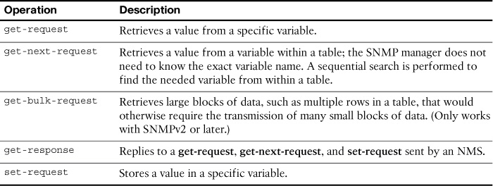
The default format for syslog messages is as follows:
seq no: timestamp: %facility-severity-MNEMONIC: description
Table 17-3 summarizes each field of the syslog message.
Using the message format and Table 17-3, you can easily interpret the following message:
00:00:46: %LINK-3-UPDOWN: Interface Port-channel1, changed state to up
The service sequence-numbers command was not configured, but the service timestamps command was configured. The facility is LINK, the severity is 3, and the MNEMONIC is UPDOWN. The rest of the message provides a description of the event.
Syslog Configuration and Verification
By default, Cisco routers and switches send log messages for all severity levels to the console. On some IOS versions, the device also buffers log messages by default. To enable these two settings, use the logging console and logging buffered global configuration commands, respectively.
The show logging command displays the default logging service settings on a Cisco router, as shown in Example 17-5.
Example 17-5 Default Logging Service Settings
R1# show logging
Syslog logging: enabled (0 messages dropped, 2 messages rate-limited, 0 flushes, 0
overruns, xml disabled, filtering disabled)
No Active Message Discriminator.
No Inactive Message Discriminator.
Console logging: level debugging, 32 messages logged, xml disabled,
filtering disabled
Monitor logging: level debugging, 0 messages logged, xml disabled,
filtering disabled
Buffer logging: level debugging, 32 messages logged, xml disabled,
filtering disabled
Exception Logging: size (4096 bytes)
Count and timestamp logging messages: disabled
Persistent logging: disabled
No active filter modules.
Trap logging: level informational, 34 message lines logged
Logging Source-Interface: VRF Name:
Log Buffer (8192 bytes):
*Jan 2 00:00:02.527: %LICENSE-6-EULA_ACCEPT_ALL: The Right to Use End User
License Agreement is accepted
*Jan 2 00:00:02.631: %IOS_LICENSE_IMAGE_APPLICATION-6-LICENSE_LEVEL: Module
name = c1900 Next reboot level = ipbasek9 and License = ipbasek9
*Jan 2 00:00:02.851: %IOS_LICENSE_IMAGE_APPLICATION-6-LICENSE_LEVEL: Module
name = c1900 Next reboot level = securityk9 and License = securityk9
*Jun 12 17:46:01.619: %IFMGR-7-NO_IFINDEX_FILE: Unable to open nvram:/ifIndex-table
No such file or directory
<output omitted>
To configure the router to send system messages to a syslog server, complete the following three steps:
Step 1 Configure the IP address of the syslog server in global configuration mode:
R1(config)# logging 192.168.1.3
Step 2 Control the messages that will be sent to the syslog server with the logging trap level global configuration mode command. For example, to limit the messages to levels 4 and lower (0 to 4), use one of the two equivalent commands:
R1(config)# logging trap 4
!or
R1(config)# logging trap warning
Step 3 Optionally, configure the source interface with the logging source-interface interface-type interface-number global configuration mode command. This specifies that syslog packets contain the address of a specific interface, regardless of which interface the packet uses to exit the router. For example, to set the source interface to g0/0, use the following command:
R1(config)# logging source-interface g0/0
Example 17-6 shows the output from the show logging command. The default settings have been changed, as noted by the highlights.
Example 17-6 Verify the Logging Service after Configuration
R1# show logging
Syslog logging: enabled (0 messages dropped, 2 messages rate-limited, 0 flushes, 0 overruns, xml disabled, filtering disabled)
No Active Message Discriminator.
No Inactive Message Discriminator.
Console logging: level debugging, 41 messages logged, xml disabled,
filtering disabled
Monitor logging: level debugging, 0 messages logged, xml disabled,
filtering disabled
Buffer logging: level debugging, 41 messages logged, xml disabled,
filtering disabled
Exception Logging: size (4096 bytes)
Count and timestamp logging messages: disabled
Persistent logging: disabled
No active filter modules.
Trap logging: level warnings, 43 message lines logged
Logging to 192.168.1.3 (udp port 514, audit disabled,
link up),
4 message lines logged,
0 message lines rate-limited,
0 message lines dropped-by-MD,
xml disabled, sequence number disabled
filtering disabled
Logging Source-Interface: VRF Name:
GigabitEthernet0/0
<output omitted>
Study Resources
For today’s exam topics, refer to the following resources for more study.
