Day 3. Troubleshooting WAN Issues
CCNA 200-101 ICND2 Exam Topics
![]() Troubleshoot and resolve WAN implementation issues
Troubleshoot and resolve WAN implementation issues
Key Topics
Today wraps up your review of WAN technologies with some tips for troubleshooting WAN implementations.
Troubleshooting WAN Implementations
Troubleshooting your overall WAN implementation (not just Frame Relay aspects) often starts with investigating the state of the local router’s serial interface. The show interfaces serial command in Example 3-1 has the default HDLC encapsulation.
Example 3-1 Output from the show interface serial Command
R1# show interface serial 0/0/0
Serial0/0/0 is up, line protocol is up (connected)
Hardware is HD64570
Description: Link to R2
Internet address is 10.1.1.1/30
MTU 1500 bytes, BW 1544 Kbit, DLY 20000 usec, rely 255/255, load 1/255
Encapsulation HDLC, loopback not set, keepalive set (10 sec)
Last input never, output never, output hang never
Last clearing of "show interface" counters never
Input queue: 0/75/0 (size/max/drops); Total output drops: 0
Queueing strategy: weighted fair
Output queue: 0/1000/64/0 (size/max total/threshold/drops)
Conversations 0/0/256 (active/max active/max total)
Reserved Conversations 0/0 (allocated/max allocated)
5 minute input rate 3 bits/sec, 0 packets/sec
5 minute output rate 2 bits/sec, 0 packets/sec
3 packets input, 210 bytes, 0 no buffer
Received 0 broadcasts, 0 runts, 0 giants, 0 throttles
0 input errors, 0 CRC, 0 frame, 0 overrun, 0 ignored, 0 abort
2 packets output, 140 bytes, 0 underruns
0 output errors, 0 collisions, 0 interface resets
0 output buffer failures, 0 output buffers swapped out
0 carrier transitions
DCD=up DSR=up DTR=up RTS=up CTS=up
Highlighted in the output are the three main areas to look first for possible errors:
![]() The interface must be up and up before it can forward traffic.
The interface must be up and up before it can forward traffic.
![]() The IP address and subnet mask must be configured correctly.
The IP address and subnet mask must be configured correctly.
![]() The encapsulation must be correct: HDLC, PPP, or Frame Relay.
The encapsulation must be correct: HDLC, PPP, or Frame Relay.
Potential errors two and three and their solutions are relatively straightforward: Correct the IP addressing or correct the encapsulation. The show interfaces serial command returns one of six possible states. You can see any of the following possible states in the interface status line:
![]() Serial x is up, line protocol is up
Serial x is up, line protocol is up
![]() Serial x is down, line protocol is down
Serial x is down, line protocol is down
![]() Serial x is up, line protocol is down
Serial x is up, line protocol is down
![]() Serial x is up, line protocol is up (looped)
Serial x is up, line protocol is up (looped)
![]() Serial x is up, line protocol is down (disabled)
Serial x is up, line protocol is down (disabled)
![]() Serial x is administratively down, line protocol is down
Serial x is administratively down, line protocol is down
Troubleshooting Layer 1 Problems
A down line status on the serial link typically points to a Layer 1 problem. The following list describes the most likely reasons:
![]() The leased line is down (a telco problem).
The leased line is down (a telco problem).
![]() The line from the telco is not plugged in to either or both channel service unit/data service units (CSU/DSUs).
The line from the telco is not plugged in to either or both channel service unit/data service units (CSU/DSUs).
![]() A CSU/DSU has failed or is misconfigured.
A CSU/DSU has failed or is misconfigured.
![]() A serial cable from a router to its CSU/DSU is disconnected or faulty.
A serial cable from a router to its CSU/DSU is disconnected or faulty.
The details of how to further isolate these four problems are beyond the scope of the CCNA exam.
One other common physical layer problem can occur that results in both routers’ interfaces being in an up/down state. On a back-to-back serial link, some older routers require the clock rate command on the side where the DCE cable is installed; otherwise, both routers’ serial interfaces will fail and end up with a line status of up but a line protocol status of down.
To check for this error, use the show controllers command on the side that should be DCE. You might be surprised to find that a DTE cable is attached. Or you might discover that no clock is set, as shown in Example 3-2.
Example 3-2 Problem: No clock rate Command on the DCE End
R1# show controllers serial 0/0/0
Interface Serial0/0/0
Hardware is PowerQUICC MPC860
DCE V.35, no clock
idb at 0x81081AC4, driver data structure at 0x81084AC0
SCC Registers:
<output omitted>
Troubleshooting Layer 2 Problems
Table 3-1 lists three common data-link layer problems.
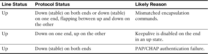
The first problem is easy to identify and fix. As you have seen, the show interfaces command tells you the encapsulation type currently used on the interface.
The second problem in Table 3-1 relates to keepalives sent by Cisco routers by default every 10 seconds. This feature helps a router recognize when a link is no longer functioning so that the router can bring down the interface, hoping to then use an alternative IP route. If one end of the link is configured with the no keepalives command, it will remain in the up and up state. However, the other side of the link will continually flap up and down because it is not receiving keepalives. You can see whether keepalives are being sent with the show interfaces command, as highlighted in the partial output in Example 3-3.
Example 3-3 Verifying Keepalives with the show interfaces Command
R1# show interfaces serial 0/0/0
Serial0/0/0 is up, line protocol is up (connected)
Hardware is HD64570
Description: Link to R2
Internet address is 10.1.1.1/30
MTU 1500 bytes, BW 1544 Kbit, DLY 20000 usec, rely 255/255, load 1/255
Encapsulation HDLC, loopback not set, keepalive set (10 sec)
Last input never, output never, output hang never
The third problem in Table 3-1 results from an authentication failure between the two routers on each side of the link. Use the debug ppp authentication command to discover the root cause of why authentication is failing.
In Example 3-4, we know that either the username or password is misconfigured on one or both sides of the link.
Example 3-4 PPP CHAP Authentication Failure in debug ppp authentication Output
R1# debug ppp authentication
PPP authentication debugging is on
Se0/0/0 PPP: Authorization required
Se0/0/0 CHAP: O CHALLENGE id 57 len 23 from "R1"
Se0/0/0 CHAP: I CHALLENGE id 66 len 23 from "R2"
Se0/0/0 CHAP: Using hostname from unknown source
Se0/0/0 CHAP: Using password from AAA
Se0/0/0 CHAP: O RESPONSE id 66 len 23 from "R1"
Se0/0/0 CHAP: I RESPONSE id 57 len 23 from "R2"
Se0/0/0 PPP: Sent CHAP LOGIN Request
Se0/0/0 PPP: Received LOGIN Response FAIL
Se0/0/0 CHAP: O FAILURE id 57 len 25 msg is "Authentication failed"
Troubleshooting Layer 3 Problems
A serial interface can be in the up and up state on both sides of the router, yet connectivity between the two routers fails because of a Layer 3 misconfiguration.
For default HDLC interfaces, if the IP addresses configured on the serial interfaces on the two routers are in different subnets, a ping to the IP address on the other end of the link will fail because the routers do not have a matching route.
Be careful with PPP in this same situation. With misconfigured IP addresses, both routers’ interfaces are in the up and up state, but the ping to the other router’s IP address actually works. PPP advertises its serial interface IP address to the other router, with a /32 prefix, which is a route to reach just that one host. So, both routers have a route with which to route packets to the other end of the link, even though two routers on opposite ends of a serial link have mismatched their IP addresses.
Although the ping to the other end of the link works, the routing protocols still do not advertise routes because of the IP subnet mismatch on the opposite ends of the link. So, when troubleshooting a network problem, do not assume that a serial interface in an up and up state is fully working, or even that a serial interface over which a ping works is fully working. Also make sure that the routing protocol is exchanging routes and that the IP addresses are in the same subnet.
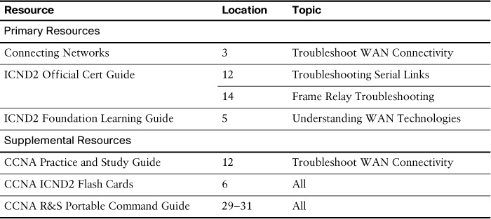
Study Resources
For today’s exam topics, refer to the following resources for more study.