Day 13. Troubleshooting Inter-VLAN Routing
CCNA 200-101 ICND2 Exam Topics
![]() Troubleshoot and resolve inter-VLAN routing problems
Troubleshoot and resolve inter-VLAN routing problems
Key Topics
Because the CCENT/ICND1 exam topics covered many of the configuration and verification commands, the topics for the next 4 days are rather unique from other topics you are reviewing for the CCNA/ICND2 exam. So, some of the study resources refer you back to CCENT study materials (where you will find many troubleshooting topics discussed). Today, the review begins with a quick look at inter-VLAN routing configuration and then covers troubleshooting potential issues.
Inter-VLAN Routing Configuration
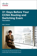
When you are configuring inter-VLAN routing using the router-on-a-stick model, the physical interface of the router must be connected to a trunk link on the adjacent switch. On the router, subinterfaces are created for each unique VLAN on the network. Each subinterface is assigned an IP address specific to its subnet/VLAN and is also configured to tag frames for that VLAN. This way, the router can keep the traffic from each subinterface separated as it traverses the trunk link back to the switch.
Configuring inter-VLAN routing is pretty straightforward. Take a look at the sample topology shown in Figure 13-1 to review the commands.
To configure this router-on-a-stick topology on the router, complete the following steps:
Step 1 Activate the physical interface that is trunking with the switch by using the no shutdown command.
Step 2 Enter subinterface configuration mode for the first VLAN that needs routing. One convention is to use the VLAN number as the subinterface number. For example, the interface g0/1.10 command enters subinterface configuration mode for VLAN 10.
Step 3 Configure the trunking encapsulation type by using the subinterface configuration command encapsulation {dot1q | isl} vlan-number [native]. Set the encapsulation to dot1q.
![]() Inter-Switch Link (ISL) encapsulation—a Cisco proprietary trunking method—existed before the IEEE 802.1Q standard, which is now the recommended best practice. However, older switches that are still in use might only support ISL. In those cases, you substitute the dot1q keyword with isl.
Inter-Switch Link (ISL) encapsulation—a Cisco proprietary trunking method—existed before the IEEE 802.1Q standard, which is now the recommended best practice. However, older switches that are still in use might only support ISL. In those cases, you substitute the dot1q keyword with isl.
![]() On some routers, the optional keyword native must be configured for the native VLAN before the router will route native VLAN traffic. Native VLAN routing is not shown in the following examples. Refer to your study resources for more on the native VLAN.
On some routers, the optional keyword native must be configured for the native VLAN before the router will route native VLAN traffic. Native VLAN routing is not shown in the following examples. Refer to your study resources for more on the native VLAN.
Step 4 Configure the IP address and subnet mask.
Step 5 Repeat Steps 2 through 4 for each additional VLAN that needs routing.
Assuming that the switch is already configured with VLANs and trunking, Example 13-1 shows the commands to configure R1 to provide routing between VLAN 10 and VLAN 30.
Example 13-1 Configuring R1 to Route Between VLANs
R1(config)# interface g0/0
R1(config-if)# no shutdown
R1(config-if)# interface g0/1.10
R1(config-subif)# encapsulation dot1q 10
R1(config-subif)# ip add 172.17.10.1 255.255.255.0
R1(config-subif)# interface g0/1.30
R1(config-subif)# encapsulation dot1q 30
R1(config-subif)# ip add 172.17.30.1 255.255.255.0
To verify the configuration, use the show vlans, show ip route, and show ip interface brief commands to ensure that the new networks are in the routing table and that the subinterfaces are up and up, as shown in Example 13-2.
Example 13-2 Verifying the Inter-VLAN Routing Configuration
R1# show vlans
<output omitted>
Virtual LAN ID: 10 (IEEE 802.1Q Encapsulation)
vLAN Trunk Interface: GigabitEthernet0/0.10
Protocols Configured: Address: Received: Transmitted:
IP 172.17.10.1 0 0
<output omitted>
Virtual LAN ID: 30 (IEEE 802.1Q Encapsulation)
vLAN Trunk Interface: GigabitEthernet0/0.30
Protocols Configured: Address: Received: Transmitted:
IP 172.17.30.1 0 0
<output omitted>
R1# show ip route
<output omitted>
Gateway of last resort is not set
172.17.0.0/16 is variably subnetted, 4 subnets, 2 masks
C 172.17.10.0/24 is directly connected, GigabitEthernet0/0.10
L 172.17.10.1/32 is directly connected, GigabitEthernet0/0.10
C 172.17.30.0/24 is directly connected, GigabitEthernet0/0.30
L 172.17.30.1/32 is directly connected, GigabitEthernet0/0.30
R1# show ip interface brief
Interface IP-Address OK? Method Status Protocol
GigabitEthernet0/0 unassigned YES unset up up
GigabitEthernet0/0.10 172.17.10.1 YES manual up up
GigabitEthernet0/0.30 172.17.30.1 YES manual up up
GigabitEthernet0/1 unassigned YES unset administratively down down
Serial0/0/0 unassigned YES manual administratively down down
Serial0/0/1 unassigned YES manual administratively down down
Vlan1 unassigned YES manual administratively down down
R1#
Assuming that the switch and PCs are configured correctly, the two PCs should now be able to ping each other. R1 will route the traffic between VLAN 10 and VLAN 30.
Inter-VLAN Routing Issues
Several common issues can occur when configuring routing between VLANs, as described in the subsections that follow.
Physical Connections
You likely have experience with physical layer connectivity issues on live equipment or lab equipment. One of the most common configuration errors is to connect the physical router interface to the wrong switch port. Obviously, this error prevents the trunking of all allowed VLAN traffic. If you are sure that your configuration is correct, check the cabling and correct any issues.
Trunking Configuration
If the trunking port is misconfigured or left in the default VLAN for the port, the router cannot route between VLANs because each of its configured subinterfaces cannot send or receive VLAN-tagged traffic. You can check for this issue with the show interfaces interface-id switchport command, as shown in Example 13-3.
Example 13-3 Isolating a Trunking Issue
S1# show interfaces gigabit0/1 switchport
Name: Gig0/1
Switchport: Enabled
Administrative Mode: static access
Operational Mode: up
Administrative Trunking Encapsulation: dot1q
Operational Trunking Encapsulation: native
Negotiation of Trunking: On
Access Mode VLAN: 1 (default)
Trunking Native Mode VLAN: 1 (default)
<output omitted>
Correct this problem by issuing the switchport mode trunk command on the trunking interface. In addition, depending on the model of switch, you may also need to configure the switchport encapsulation dot1q command before the switchport mode trunk command.
IP Addressing Issues
For inter-VLAN routing to operate, a router must be connected to all VLANs, either by separate physical interfaces or by subinterfaces. Each interface, or subinterface, must be assigned an IP address that corresponds to the subnet to which it is connected. The following are some common IP addressing errors:
![]() Incorrect IP address and subnet combination assigned to the router interface or subinterface
Incorrect IP address and subnet combination assigned to the router interface or subinterface
![]() End devices configured with the incorrect IP address for the VLAN subnet
End devices configured with the incorrect IP address for the VLAN subnet
![]() End devices configured with the incorrect subnet mask for the VLAN subnet
End devices configured with the incorrect subnet mask for the VLAN subnet
![]() End devices configured with the incorrect default gateway address
End devices configured with the incorrect default gateway address
Use the show running-config and show ip interface commands to check the IP addressing configuration on the router. Check the end device’s IP configuration. For Windows PCs, use the ipconfig command.
Study Resources
For today’s exam topics, refer to the following resources for more study.
