Day 9. WAN Technology Overview
CCNA 200-101 ICND2 Exam Topics
![]() Identify different WAN technologies
Identify different WAN technologies
Key Topics
WAN services are always a consideration in today’s networks. Except for situations that require absolutely no remote access (such as workstations that need to be protected from outside access), every device needs some type of WAN service to reach remote destinations and the Internet. Today’s review provides an overview of WAN technologies. Tomorrow’s review covers WAN connection options, virtual private networks (VPNs), and generic routing encapsulation (GRE).
WAN Technology Concepts
WAN access standards typically describe both physical layer delivery methods and data-link layer requirements, including physical addressing, flow control, and encapsulation. The physical layer protocols describe how to provide electrical, mechanical, operational, and functional connections to a service provider. The data-link layer protocols define how data is encapsulated and the mechanisms for transferring the resulting frames. A variety of technologies are used, such as Frame Relay and Asynchronous Transfer Mode (ATM). Some of these protocols use the same basic framing mechanism as High-Level Data Link Control (HDLC), an ISO standard, or one of its subsets or variants.
WAN Components
Figure 9-1 illustrates the terminology commonly used to describe physical WAN connections.
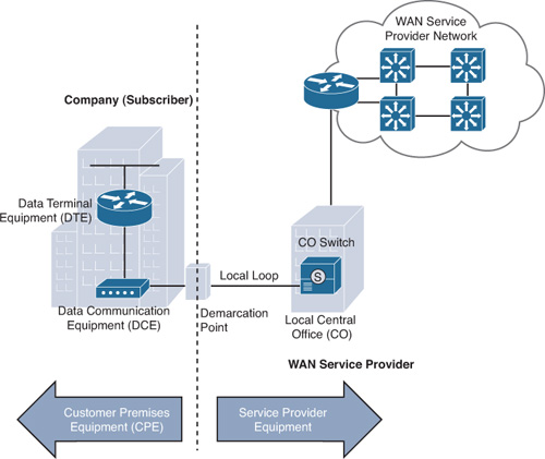
The WAN components shown in Figure 9-1 are described in further detail in the following list:
![]() Customer premises equipment (CPE): The devices located at the premises of the WAN subscriber. The subscriber either owns or leases the CPE.
Customer premises equipment (CPE): The devices located at the premises of the WAN subscriber. The subscriber either owns or leases the CPE.
![]() Data communications equipment (DCE): Consists of devices that put data on the local loop. The DCE primarily provides an interface to connect subscribers to the WAN cloud.
Data communications equipment (DCE): Consists of devices that put data on the local loop. The DCE primarily provides an interface to connect subscribers to the WAN cloud.
![]() Data terminal equipment (DTE): The customer devices that pass the data from a customer network to the DCE for transmission over the WAN.
Data terminal equipment (DTE): The customer devices that pass the data from a customer network to the DCE for transmission over the WAN.
![]() Local loop: The copper or fiber cable that connects the CPE to the central office (CO) of the service provider. The local loop is sometimes called the last mile.
Local loop: The copper or fiber cable that connects the CPE to the central office (CO) of the service provider. The local loop is sometimes called the last mile.
![]() Demarcation point: A point where customer equipment is separated from service provider equipment. It is the place where the responsibility for the connection changes from the customer to the service provider.
Demarcation point: A point where customer equipment is separated from service provider equipment. It is the place where the responsibility for the connection changes from the customer to the service provider.
![]() Central office (CO): A local service provider facility or building where local cables link to long-haul, all-digital, fiber-optic communications lines through a system of switches and other equipment.
Central office (CO): A local service provider facility or building where local cables link to long-haul, all-digital, fiber-optic communications lines through a system of switches and other equipment.
WAN Devices
Figure 9-2 shows the name and typical location of various WAN devices.

WANs use numerous types of devices that are specific to WAN environments:
![]() Dialup modem: Modulates and demodulates between analog and digital signals.
Dialup modem: Modulates and demodulates between analog and digital signals.
![]() CSU/DSU: A channel service unit (CSU) and a data service unit (DSU) are often combined into a single piece of equipment to provide the termination for the digital signal and ensure connection integrity through error correction and line monitoring. It interprets frames from the carrier into frames that LAN devices can interpret and vice versa.
CSU/DSU: A channel service unit (CSU) and a data service unit (DSU) are often combined into a single piece of equipment to provide the termination for the digital signal and ensure connection integrity through error correction and line monitoring. It interprets frames from the carrier into frames that LAN devices can interpret and vice versa.
![]() Broadband modem: Digital modem similar to voice modems but use higher broadband frequencies; used with digital subscriber line (DSL) or cable service.
Broadband modem: Digital modem similar to voice modems but use higher broadband frequencies; used with digital subscriber line (DSL) or cable service.
![]() Access server: Concentrates dial-in and dial-out user communications. An access server might have a mixture of analog and digital interfaces and support hundreds of simultaneous users.
Access server: Concentrates dial-in and dial-out user communications. An access server might have a mixture of analog and digital interfaces and support hundreds of simultaneous users.
![]() WAN switch: A multiport internetworking device used in carrier networks. These devices typically switch traffic such as Frame Relay, ATM, or X.25 and operate at the data-link layer of the OSI reference model. Public switched telephone network (PSTN) switches might also be used within the cloud for circuit-switched connections such as (ISDN) or analog dialup.
WAN switch: A multiport internetworking device used in carrier networks. These devices typically switch traffic such as Frame Relay, ATM, or X.25 and operate at the data-link layer of the OSI reference model. Public switched telephone network (PSTN) switches might also be used within the cloud for circuit-switched connections such as (ISDN) or analog dialup.
![]() Router: Provides internetworking and WAN access interface ports that are used to connect to the service provider network.
Router: Provides internetworking and WAN access interface ports that are used to connect to the service provider network.
![]() Core router/multilayer switch: A router or multilayer switch that resides within the middle or backbone of the WAN rather than at its periphery. To fulfill this role, a router must be able to support multiple telecommunications interfaces of the highest speed in use in the WAN core, and it must be able to forward IP packets at full speed on all those interfaces. The router must also support the routing protocols in use in the core.
Core router/multilayer switch: A router or multilayer switch that resides within the middle or backbone of the WAN rather than at its periphery. To fulfill this role, a router must be able to support multiple telecommunications interfaces of the highest speed in use in the WAN core, and it must be able to forward IP packets at full speed on all those interfaces. The router must also support the routing protocols in use in the core.
WAN Operations
This section reviews the WAN physical and data-link layer standards and the types of switching used in WAN technologies.
WAN Physical Layer Standards
The WAN physical layer also describes the interface between the DTE and DCE. A Cisco router’s serial interface is capable of connecting to a CSU/DSU that uses any of the following standards:
![]() EIA/TIA-232: This protocol allows signal speeds of up to 64 kbps on a 25-pin D-connector over short distances. It was formerly known as RS-232. The ITU-T V.24 specification is effectively the same.
EIA/TIA-232: This protocol allows signal speeds of up to 64 kbps on a 25-pin D-connector over short distances. It was formerly known as RS-232. The ITU-T V.24 specification is effectively the same.
![]() EIA/TIA-449/530: This protocol is a faster (up to 2 Mbps) version of EIA/TIA-232. It uses a 36-pin D-connector and is capable of longer cable runs. Several versions exist. This standard is also known as RS-422 and RS-423.
EIA/TIA-449/530: This protocol is a faster (up to 2 Mbps) version of EIA/TIA-232. It uses a 36-pin D-connector and is capable of longer cable runs. Several versions exist. This standard is also known as RS-422 and RS-423.
![]() V.35: This is the ITU-T standard for synchronous communications between a network access device and a packet network. Originally specified to support data rates of 48 kbps, it now supports speeds of up to 2.048 Mbps using a 39-pin rectangular connector.
V.35: This is the ITU-T standard for synchronous communications between a network access device and a packet network. Originally specified to support data rates of 48 kbps, it now supports speeds of up to 2.048 Mbps using a 39-pin rectangular connector.
![]() X.21: This protocol is an ITU-T standard for synchronous digital communications. It uses a 15-pin D-connector.
X.21: This protocol is an ITU-T standard for synchronous digital communications. It uses a 15-pin D-connector.
![]() EIA/TIA-612/613: (not shown in Figure 9-3) This standard describes the High-Speed Serial Interface (HSSI) protocol, which provides access to services up to 52 Mbps on a 60-pin D-connector.
EIA/TIA-612/613: (not shown in Figure 9-3) This standard describes the High-Speed Serial Interface (HSSI) protocol, which provides access to services up to 52 Mbps on a 60-pin D-connector.
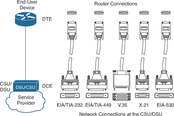
Notice in Figure 9-3 that the router connection at the top is the same regardless of the connection used by CSU/DSU. The network administrator simply chooses the correct cable for the CSU/DSU connection.
WAN Data-Link Protocols
Each WAN connection type uses a Layer 2 protocol to encapsulate a packet while it is crossing the WAN link. To ensure that the correct encapsulation protocol is used, you must configure the Layer 2 encapsulation type used for each router serial interface if different from the default. The choice of encapsulation protocols depends on the WAN technology and the equipment. The most common WAN data-link protocols are as follows:
![]() HDLC (Cisco default)
HDLC (Cisco default)
![]() Point-to-Point Protocol (PPP)
Point-to-Point Protocol (PPP)
![]() Frame Relay
Frame Relay
WAN Switching
WAN switched networks are categorized as either circuit-switched or packet-switched. A circuit-switched network is one that establishes a dedicated circuit (or channel) between nodes and terminals before the users can communicate. Although the circuit is dedicated for the duration of the call, the physical link is shared by multiple end users through a process called time-division multiplexing (TDM). TDM gives each conversation a share of the connection in turn and ensures that a fixed-capacity connection is made available to the subscriber. PSTN and ISDN are two types of circuit-switching technology that can be used to implement a WAN in an enterprise setting.
In contrast to circuit switching, packet switching splits traffic data into packets that are routed over a shared network. Packet-switching networks do not require a circuit to be established, and they allow many pairs of end users to communicate over the same channel. The switches in a packet-switched network use one of the following methods to determine which link the packet must be sent on next from the addressing information in each packet:
![]() Connectionless systems, such as the Internet, carry full addressing information in each packet. Each packet switch or router must evaluate the destination IP address to determine where to send the packet.
Connectionless systems, such as the Internet, carry full addressing information in each packet. Each packet switch or router must evaluate the destination IP address to determine where to send the packet.
![]() Connection-oriented systems predetermine a packet’s route, and each packet only has to carry an identifier, such as data-link connection identifiers (DLCIs) in Frame Relay.
Connection-oriented systems predetermine a packet’s route, and each packet only has to carry an identifier, such as data-link connection identifiers (DLCIs) in Frame Relay.
Packet-switched networks can establish routes through the switches for particular end-to-end connections. These routes are called virtual circuits (VCs). A VC is a logical circuit between two network devices to help ensure reliable communications. Two types of VCs exist:
![]() Permanent virtual circuit (PVC): A permanently established VC that consists of one mode: data transfer. PVCs are used in situations in which data transfer between devices is constant.
Permanent virtual circuit (PVC): A permanently established VC that consists of one mode: data transfer. PVCs are used in situations in which data transfer between devices is constant.
![]() Switched virtual circuit (SVC): A VC that is dynamically established on demand and terminated when transmission is complete. Communication over an SVC consists of three phases: circuit establishment, data transfer, and circuit termination. SVCs are used in situations in which data transmission between devices is intermittent, largely to save costs.
Switched virtual circuit (SVC): A VC that is dynamically established on demand and terminated when transmission is complete. Communication over an SVC consists of three phases: circuit establishment, data transfer, and circuit termination. SVCs are used in situations in which data transmission between devices is intermittent, largely to save costs.
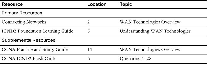
Study Resources
For today’s exam topics, refer to the following resources for more study.