Day 5. Frame Relay
CCNA 200-101 ICND2 Exam Topics
![]() Configure and verify Frame Relay on Cisco routers
Configure and verify Frame Relay on Cisco routers
Key Topics
Today you finish your review of CCNA exam topics with a look at Frame Relay and basic WAN troubleshooting. Frame Relay is currently the most popular choice for WAN implementations. Therefore, you must have a basic understanding of Frame Relay, including its conceptual framework, configuration, and verification. As a final topic, this review covers various WAN errors and their potential causes.
Frame Relay Concepts
Frame Relay is a connection-oriented data-link technology that is streamlined to provide high performance and efficiency. For error protection, it relies on upper-layer protocols and dependable fiber and digital networks.
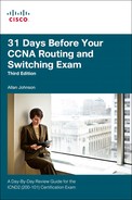
Frame Relay defines the interconnection process between the router and the local Frame Relay switch of the service provider, as shown in Figure 5-1.
Devices attached to a Frame Relay WAN fall into the following two categories:
![]() Data terminal equipment (DTE): Examples of DTE devices include Frame Relay access devices (FRADs), routers, and bridges.
Data terminal equipment (DTE): Examples of DTE devices include Frame Relay access devices (FRADs), routers, and bridges.
![]() Data communications equipment (DCE): In most cases, the Frame Relay switches in a WAN.
Data communications equipment (DCE): In most cases, the Frame Relay switches in a WAN.
Frame Relay Components
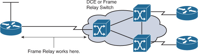
Frame Relay provides a means for statistically multiplexing many logical data conversations, referred to as virtual circuits (VCs), over a single physical transmission link by assigning connection identifiers to each pair of DTE devices. The service provider switching equipment constructs a switching table that maps the connection identifier to outbound ports. When a frame is received, the switching device analyzes the connection identifier and delivers the frame to the associated outbound port. The complete path to the destination is established before the transmission of the first frame. Figure 5-2 illustrates a Frame Relay connection and identifies the many components within Frame Relay.
The following terms are often used in Frame Relay discussions:
![]() Local access rate: The rate at which data travels into or out of the network, regardless of other settings.
Local access rate: The rate at which data travels into or out of the network, regardless of other settings.
![]() Virtual circuit (VC): Logical circuit, uniquely identified by a data-link connection identifier (DLCI), that is created to ensure bidirectional communication from one DTE device to another.
Virtual circuit (VC): Logical circuit, uniquely identified by a data-link connection identifier (DLCI), that is created to ensure bidirectional communication from one DTE device to another.
![]() Permanent virtual circuit (PVC): Provides permanently established connections that are used for frequent and consistent data transfers.
Permanent virtual circuit (PVC): Provides permanently established connections that are used for frequent and consistent data transfers.
![]() Switched virtual circuit (SVC): Provides temporary connections that are used in situations that require only sporadic data transfer between DTE devices across the Frame Relay network.
Switched virtual circuit (SVC): Provides temporary connections that are used in situations that require only sporadic data transfer between DTE devices across the Frame Relay network.
![]() Data-link connection identifier (DLCI): Contains a 10-bit number in the Address field of the Frame Relay frame header that identifies the VC. DLCIs have local significance because the identifier references the point between the local router and the local Frame Relay switch to which the DLCI is connected. Therefore, devices at opposite ends of a connection can use different DLCI values to refer to the same virtual connection.
Data-link connection identifier (DLCI): Contains a 10-bit number in the Address field of the Frame Relay frame header that identifies the VC. DLCIs have local significance because the identifier references the point between the local router and the local Frame Relay switch to which the DLCI is connected. Therefore, devices at opposite ends of a connection can use different DLCI values to refer to the same virtual connection.
As shown in Figure 5-2, Router A has two VCs that are configured on one physical interface. A DLCI of 100 identifies the VC that connects to Router B. A DLCI of 400 identifies the VC that connects to Router C. At the other end, a different DLCI number can be used to identify the VC.
![]() Committed information rate (CIR): When subscribing to a Frame Relay service, you specify the CIR, which is the local access rate (for example, 56 kbps or T1). Typically, you are also asked to specify a CIR for each DLCI. If you send information faster than the CIR on a given DLCI, the network flags some frames with a discard eligible (DE) bit.
Committed information rate (CIR): When subscribing to a Frame Relay service, you specify the CIR, which is the local access rate (for example, 56 kbps or T1). Typically, you are also asked to specify a CIR for each DLCI. If you send information faster than the CIR on a given DLCI, the network flags some frames with a discard eligible (DE) bit.
![]() Inverse Address Resolution Protocol (ARP): A method of dynamically associating the network layer address of the remote router with a local DLCI.
Inverse Address Resolution Protocol (ARP): A method of dynamically associating the network layer address of the remote router with a local DLCI.
![]() Local Management Interface (LMI): A signaling standard between the router (DTE device) and the local Frame Relay switch (DCE device) that is responsible for managing the connection and maintaining status between the router and the Frame Relay switch.
Local Management Interface (LMI): A signaling standard between the router (DTE device) and the local Frame Relay switch (DCE device) that is responsible for managing the connection and maintaining status between the router and the Frame Relay switch.
![]() Forward explicit congestion notification (FECN): A bit in the Address field of the Frame Relay frame header. If the network is congested, DCE devices (Frame Relay switches) set the FECN bit value of the frames to 1 to signal downstream DTE devices that flow control might be warranted.
Forward explicit congestion notification (FECN): A bit in the Address field of the Frame Relay frame header. If the network is congested, DCE devices (Frame Relay switches) set the FECN bit value of the frames to 1 to signal downstream DTE devices that flow control might be warranted.
![]() Backward explicit congestion notification (BECN): A bit in the Address field of the Frame Relay frame header. Operates like the FECN bit but travels in the opposite direction, informing upstream DTE devices that congestion is occurring and that flow control might be warranted.
Backward explicit congestion notification (BECN): A bit in the Address field of the Frame Relay frame header. Operates like the FECN bit but travels in the opposite direction, informing upstream DTE devices that congestion is occurring and that flow control might be warranted.
Frame Relay Topologies
Frame Relay allows you to interconnect your remote sites in a variety of topologies.
Figure 5-3 illustrates these topologies, which are described in the list that follows:
![]() Partial-mesh topology: Not all sites have direct access to all other sites.
Partial-mesh topology: Not all sites have direct access to all other sites.
![]() Full-mesh topology: All routers have VCs to all other destinations. Use the n (n – 1) / 2 formula to calculate the total number of links that are required to implement a full-mesh topology, where n is the number of endpoints (nodes).
Full-mesh topology: All routers have VCs to all other destinations. Use the n (n – 1) / 2 formula to calculate the total number of links that are required to implement a full-mesh topology, where n is the number of endpoints (nodes).
![]() Star topology: The star topology, also known as a hub-and-spoke configuration, is the least-expensive topology because it requires the fewest number of PVCs.
Star topology: The star topology, also known as a hub-and-spoke configuration, is the least-expensive topology because it requires the fewest number of PVCs.

NBMA Limitations and Solutions
By default, a Frame Relay network provides nonbroadcast multi-access (NBMA) connectivity between remote sites. An NBMA environment is treated like other broadcast media environments, such as Ethernet, where all the routers are on the same subnet.
However, to reduce cost, network designers usually build NBMA clouds in a hub-and-spoke topology. With a hub-and-spoke topology, the physical topology does not provide the multi-access capabilities that Ethernet does, so each router might not have separate PVCs to reach the other remote routers on the same subnet. Split horizon is one of the main issues you encounter when Frame Relay is running multiple PVCs over a single interface.
In any Frame Relay topology, when a single interface must be used to interconnect multiple sites, you can have reachability issues because of the NBMA nature of Frame Relay. The Frame Relay NBMA topology can cause the following two problems:
![]() Routing update reachability: Split horizon prevents a routing update that is received on an interface from being forwarded out the same interface. So, a hub router will not send updates from one spoke router to another spoke router if the update must go out the same interface. (Split horizon applies only to distance vector routing protocols.)
Routing update reachability: Split horizon prevents a routing update that is received on an interface from being forwarded out the same interface. So, a hub router will not send updates from one spoke router to another spoke router if the update must go out the same interface. (Split horizon applies only to distance vector routing protocols.)
![]() Broadcast replication: With routers that support multipoint connections over a single interface that terminate many PVCs, the router must replicate broadcast packets, such as routing update broadcasts, on each PVC to the remote routers. These replicated broadcast packets consume bandwidth and cause significant latency variations in user traffic.
Broadcast replication: With routers that support multipoint connections over a single interface that terminate many PVCs, the router must replicate broadcast packets, such as routing update broadcasts, on each PVC to the remote routers. These replicated broadcast packets consume bandwidth and cause significant latency variations in user traffic.
The following methods exist to solve the routing update reachability issue:
![]() Turn off split horizon; however, disabling split horizon increases the chances of routing loops in your network. (Split horizon is not an issue if you use a link-state routing protocol.)
Turn off split horizon; however, disabling split horizon increases the chances of routing loops in your network. (Split horizon is not an issue if you use a link-state routing protocol.)
![]() Use a fully meshed topology; however, this topology increases the cost.
Use a fully meshed topology; however, this topology increases the cost.
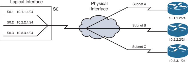
![]() Use subinterfaces. When you use a Frame Relay point-to-point subinterface, each subinterface is on its own subnet.
Use subinterfaces. When you use a Frame Relay point-to-point subinterface, each subinterface is on its own subnet.
Figure 5-4 shows how to resolve the issues using subinterfaces.
Inverse ARP and LMI Concepts
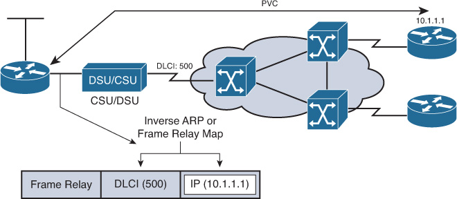
Routers can automatically discover their local DLCI from the local Frame Relay switch using the LMI protocol. Then the local DLCI can be dynamically mapped to the remote router network layer addresses with Inverse ARP.
As shown in Figure 5-5, using Inverse ARP, the router on the left can automatically discover the remote router IP address and then map it to the local DLCI. In this case, the local DLCI of 500 is mapped to the 10.1.1.1 IP address.
Frame Relay signaling is required between the router and the Frame Relay switch. Figure 5-6 shows how the signaling is used to get information about the different DLCIs.
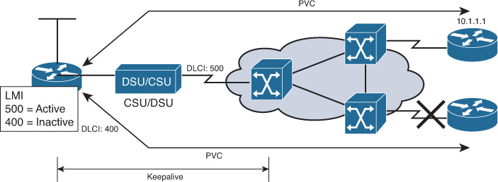
The LMI is a signaling standard between the router and the Frame Relay switch. The LMI is responsible for managing the connection and maintaining the status between the devices.
Although the LMI is configurable, the Cisco router tries (beginning in Cisco IOS Release 11.2) to autosense which LMI type the Frame Relay switch is using. The router sends one or more full LMI status requests to the Frame Relay switch. The Frame Relay switch responds with one or more LMI types, and the router configures itself with the last LMI type received. Cisco routers support the following three LMI types: Cisco, ANSI, and Q933A.
When the router receives LMI information, it updates its VC status to one of the following three states:
![]() Active: Indicates that the VC connection is active and that routers can exchange data over the Frame Relay network
Active: Indicates that the VC connection is active and that routers can exchange data over the Frame Relay network
![]() Inactive: Indicates that the local connection to the Frame Relay switch is working but that the remote router connection to the remote Frame Relay switch is not working
Inactive: Indicates that the local connection to the Frame Relay switch is working but that the remote router connection to the remote Frame Relay switch is not working
![]() Deleted: Indicates that either no LMI is being received from the Frame Relay switch or that no service exists between the router and local Frame Relay switch
Deleted: Indicates that either no LMI is being received from the Frame Relay switch or that no service exists between the router and local Frame Relay switch
Inverse ARP and LMI Operation
The following is a summary of how Inverse ARP and LMI signaling work with a Frame Relay connection:
1. Each router connects to the Frame Relay switch through a channel service unit/data service unit (CSU/DSU).
2. When Frame Relay is configured on an interface, the router sends an LMI status inquiry message to the Frame Relay switch. The message notifies the switch of the router status and asks the switch for the connection status of the router VCs.
3. When the Frame Relay switch receives the request, it responds with an LMI status message that includes the local DLCIs of the PVCs to the remote routers to which the local router can send data.
4. For each active DLCI, each router sends an Inverse ARP packet to introduce itself.
Figure 5-7 illustrates the first four steps of this process.

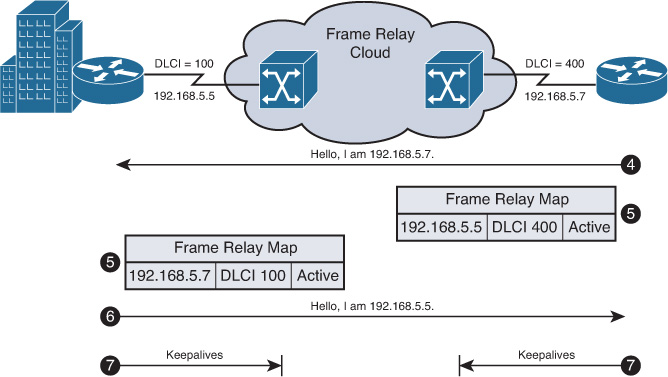
5. When a router receives an Inverse ARP message, it creates a map entry in its Frame Relay map table that includes the local DLCI and the remote router network layer address.
6. Every 60 seconds, routers send Inverse ARP messages on all active DLCIs. Every 10 seconds, the router exchanges LMI information with the switch (keepalives).
7. The router changes the status of each DLCI to active, inactive, or deleted, based on the LMI response from the Frame Relay switch.
Figure 5-8 illustrates Steps 5–7 of this process.
Configuring and Verifying Frame Relay
To configure Frame Relay, complete the following steps:
Step 1 Configure the physical interface to use Frame Relay encapsulation (encapsulation frame-relay interface subcommand).
Step 2 Configure an IP address on the interface or subinterface (ip address subcommand).
Step 3 (Optional) Manually set the LMI type on each physical serial interface (frame-relay lmi-type interface subcommand).
Step 4 (Optional) Change from the default encapsulation of cisco to ietf by doing the following:
a. For all VCs on the interface, add the ietf keyword to the encapsulation frame-relay interface subcommand.
b. For a single VC, add the ietf keyword to the frame-relay interface dlci interface subcommand (point-to-point subinterfaces only) or to the frame-relay map command.
Step 5 (Optional) If you aren’t using the (default) Inverse ARP to map the DLCI to the next-hop router’s IP address, define static mapping using the frame-relay map ip dlci ip-address broadcast subinterface subcommand.
Step 6 On subinterfaces, associate one (point-to-point) or more (multipoint) DLCIs with the subinterface in one of two ways:
a. Using the frame-relay interface-dlci dlci subinterface subcommand
b. As a side effect of static mapping using the frame-relay map ip dlci ip-address broadcast subinterface subcommand
Full Mesh with One Subnet
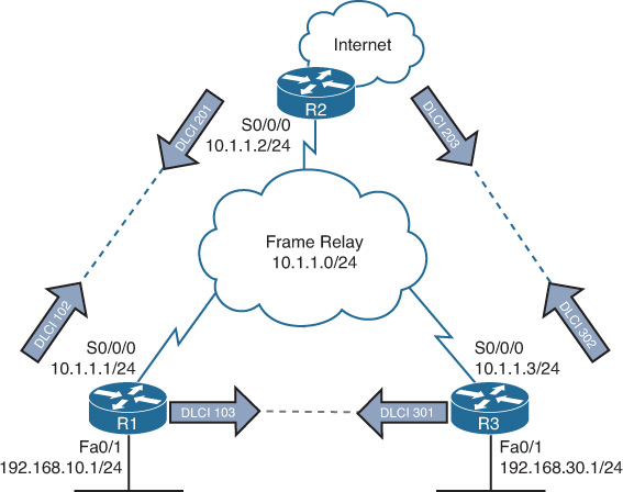
The first example shows the briefest possible Frame Relay configuration (one that uses just the first two steps of the configuration checklist in this chapter). For the topology shown in Figure 5-9, configure a full-mesh Frame Relay network using subnet 10.1.1.0/24. Use default settings for LMI, Inverse ARP, and encapsulation. Example 5-1 shows the full configuration using Enhance Interior Gateway Routing Protocol (EIGRP) as the routing protocol.
Example 5-1 Configuring Frame Relay Full Mesh with One Subnet: R1
R1(config)# interface serial 0/0/0
R1(config-if)# encapsulation frame-relay
R1(config-if)# ip address 10.1.1.1 255.255.255.0
R1(config-if)# no shutdown
R1(config-if)# interface fastethernet 0/0
R1(config-if)# ip address 192.168.10.1 255.255.255.0
R1(config-if)# no shutdown
R1(config-if)# router eigrp 1
R1(config-router)# network 10.0.0.0
R1(config-router)# network 192.168.10.0
R2(config)# interface serial 0/0/0
R2(config-if)# encapsulation frame-relay
R2(config-if)# ip address 10.1.1.2 255.255.255.0
R2(config-if)# no shutdown
R2(config-if)# router eigrp 1
R2(config-router)# network 10.0.0.0
R3(config)# interface serial 0/0/0
R3(config-if)# encapsulation frame-relay
R3(config-if)# ip address 10.1.1.3 255.255.255.0
R3(config-if)# no shutdown
R3(config-if)# interface fastethernet 0/0
R3(config-if)# ip address 192.168.30.1 255.255.255.0
R3(config-if)# no shutdown
R3(config-if)# router eigrp 1
R3(config-router)# network 10.0.0.0
R3(config-router)# network 192.168.30.0
This simple configuration takes advantage of the following IOS default settings:
![]() The LMI type is automatically sensed.
The LMI type is automatically sensed.
![]() The (default) encapsulation is Cisco instead of IETF.
The (default) encapsulation is Cisco instead of IETF.
![]() PVC DLCIs are learned via LMI status messages.
PVC DLCIs are learned via LMI status messages.
![]() Inverse ARP is enabled (by default) and is triggered when the status message declaring that the VCs are up is received.
Inverse ARP is enabled (by default) and is triggered when the status message declaring that the VCs are up is received.
Configuring the Encapsulation
If one of the routers in a full-mesh, one-subnet configuration does not support the Cisco Frame Relay encapsulation, change the encapsulation to IETF on the Cisco routers with the following command:
Router(config-if)# encapsulation frame-relay ietf
Configuring the LMI Type
LMI operates between the local router and the local Frame Relay switch. The LMI message type used by the local Frame Relay switch might need to be hard-coded on the local router, either because the IOS version does not support autosensing or because network administration policy requires that the LMI type be documented on the interface for verification and troubleshooting purposes. Assume that the Frame Relay switch used by R2 is an ANSI switch. The following command would change the LMI type on R2 to use the ANSI LMI type:
R2(config)# interface serial 0/0/0
R2(config-if)# frame-relay lmi-type ansi
The LMI setting is a per-physical-interface setting, even if subinterfaces are used, so the frame-relay lmi-type command is always a subcommand under the physical interface.
Configuring Static Frame Relay Maps
Although the DLCIs for each PVC are shown in Figure 5-9, they were not needed for our basic Frame Relay configuration. Inverse ARP automatically mapped the remote IP address with the necessary local DLCI to reach the remote network. You can verify this dynamic process with the show frame-relay pvc and show frame-relay map commands, as shown in Example 5-2 for R2.
Example 5-2 Verifying Inverse ARP with show frame-relay Commands
R2# show frame-relay pvc
PVC Statistics for interface Serial0/0/0 (Frame Relay DTE)
DLCI = 201, DLCI USAGE = LOCAL, PVC STATUS = ACTIVE, INTERFACE = Serial0/0/0
input pkts 14055 output pkts 32795 in bytes 1096228
out bytes 6216155 dropped pkts 0 in FECN pkts 0
in BECN pkts 0 out FECN pkts 0 out BECN pkts 0
in DE pkts 0 out DE pkts 0
out bcast pkts 32795 out bcast bytes 6216155
DLCI = 203, DLCI USAGE = LOCAL, PVC STATUS = ACTIVE, INTERFACE = Serial0/0/0
input pkts 14055 output pkts 32795 in bytes 1096228
out bytes 6216155 dropped pkts 0 in FECN pkts 0
in BECN pkts 0 out FECN pkts 0 out BECN pkts 0
in DE pkts 0 out DE pkts 0
out bcast pkts 32795 out bcast bytes 6216155
R2# show frame-relay map
Serial0/0/0 (up): ip 10.1.1.1 dlci 201, dynamic,
broadcast, CISCO, status defined, active
Serial0/0/0 (up): ip 10.1.1.3 dlci 203, dynamic,
broadcast, CISCO, status defined, active
In a production network you would probably use Inverse ARP, but for the exam you need to know how to configure the static map command statements. Example 5-3 lists the static Frame Relay map for the three routers shown in Figure 5-9, along with the configuration used to disable Inverse ARP.
Example 5-3 Manually Configuring Frame Relay Mapping
R1(config)# interface s0/0/0
R1(config-if)# frame-relay map ip 10.1.1.2 102 broadcast
R1(config-if)# frame-relay map ip 10.1.1.3 103 broadcast
R2(config)# interface serial 0/0/0
R2(config-if)# frame-relay map ip 10.1.1.1 201 broadcast
R2(config-if)# frame-relay map ip 10.1.1.3 203 broadcast
R3(config)# interface serial 0/0/0
R3(config-if)# frame-relay map ip 10.1.1.1 301 broadcast
R3(config-if)# frame-relay map ip 10.1.1.2 302 broadcast
Note
The broadcast keyword is required when the router needs to send broadcasts or multicasts to the neighboring router (for example, to support routing protocol messages such as hellos).
Partial Mesh with One Subnet per PVC
The network in Figure 5-10 is a modification of Figure 5-9. R2 is now serving as the hub router for the spoke routers R1 and R2. This reduces the cost of the Frame Relay implementation from three PVCs to two PVCs. This configuration uses one subnet per PVC and point-to-point subinterfaces. Example 5-4 shows the configuration for this network.

Example 5-4 Configuring Frame Relay Partial Mesh with One Subnet per PVC
R1(config-if)# encapsulation frame-relay
R1(config)# interface serial0/0/0.102 point-to-point
R1(config-subif)# ip address 10.1.1.2 255.255.255.0
R1(config-subif)# frame-relay interface-dlci 102
R2(config)# interface serial 0/0/0
R2(config-if)# encapsulation frame-relay
R2(config-if)# interface serial 0/0/0.201 point-to-point
R2(config-subif)# ip address 10.1.1.1 255.255.255.0
R2(config-subif)# frame-relay interface-dlci 201
R2(config-subif)# interface serial 0/0/0.203 point-to-point
R2(config-subif)# ip address 10.3.3.1 255.255.255.0
R2(config-subif)# frame-relay interface-dlci 203
R3(config)# interface serial 0/0/0
R3(config-if)# encapsulation frame-relay
R3(config-if)# interface serial 0/0/0.302 point-to-point
R3(config-subif)# ip address 10.3.3.2 255.255.255.0
R3(config-subif)# frame-relay interface-dlci 302
Two new commands create the configuration required with point-to-point subinterfaces. First, the interface serial 0/0/0.201 point-to-point command creates logical subinterface number 201 under physical interface Serial 0/0/0 on R2. The frame-relay interface-dlci 201 subinterface subcommand then tells the router which single DLCI is associated with that subinterface. In the example, subinterface numbers and DLCIs match, but this is not a requirement, just a convenient method to help identify which DLCI the subinterface belongs to.
To understand why you need the frame-relay interface-dlci command, consider R2. R2 receives LMI messages on serial 0/0/0 stating that two PVCs, with DLCIs 201 and 203, are up. Which PVC goes with which subinterface? Cisco IOS Software needs to associate the correct PVC with the correct subinterface. This is accomplished with the frame-relay interface-dlci command.
Frame Relay Verification
Examples of the show frame-relay pvc and show frame-relay map commands were shown previously in Example 5-2. The show frame-relay pvc command lists useful management information. For instance, the packet counters for each VC, plus the counters for FECN and BECN, can prove particularly useful. Likewise, comparing the packets/bytes sent on one router versus the counters of what is received on the router on the other end of the VC is also quite useful. This reflects the number of packets/bytes lost inside the Frame Relay cloud. Also, the PVC status is a great place to start when troubleshooting.
The show frame-relay map command lists mapping information. In a fully meshed network, in which the configuration does not use any subinterfaces, a Layer 3 address is listed with each DLCI. For a point-to-point subinterface configuration, a DLCI is listed in each entry, but no mention of corresponding Layer 3 addresses is made. The reason is that the information is stored somewhere else. Subinterfaces require the use of the frame-relay interface-dlci configuration command.
The debug frame-relay lmi command shown in Example 5-5 can be used to verify that the physical interface is sending and receiving LMI messages from the local Frame Relay switch.
Example 5-5 Frame Relay debug Output
R2# debug frame-relay lmi
Serial0/0/0(out): StEnq, myseq 1, yourseen 0, DTE up
datagramstart = 0xE7829994, datagramsize = 13
FR encap = 0x00010308
00 75 51 01 00 53 02 01 00
Serial0/0/0(in): Status, myseq 1, pak size 21
RT IE 1, length 1, type 0
KA IE 3, length 2, yourseq 1 , myseq 1
PVC IE 0x7 , length 0x6 , dlci 201, status 0x0 , bw 0
Note
If you bought Wendell Odom’s Cisco CCNA Routing and Switching 200-120 Network Simulator, you are in luck! He developed 19 Frame Relay configuration and verification scenarios, many of which include OSPF or EIGRP implementations.
Study Resources
For today’s exam topics, refer to the following resources for more study.