
Day 21. EIGRP for IPv4 Implementation
CCNA 200-101 ICND2 Exam Topics
![]() Configure and verify EIGRP (single AS)
Configure and verify EIGRP (single AS)
Key Topics
EIGRP is easy to get up and running with a basic configuration. To take full advantage of EIGRP, however, you must complete a variety of configuration tasks to modify the basic configuration. Today’s review covers EIGRP for IPv4 configuration, verification, and modification.
Configuring EIGRP for IPv4
This section covers the basics of configuring EIGRP for IPv4, including the network and router-id commands.
EIGRP Topology and Addressing Scheme
This review of the EIGRP configuration commands uses the topology in Figure 21-1 and the addressing scheme in Table 21-1.


The network Command
Assuming the interfaces of all the routers are configured and activated according to the IP addresses in Table 21-1, Example 21-1 shows the EIGRP configuration using the network command.
Example 21-1 EIGRP Configuration
R1(config)# router eigrp 1
R1(config-router)# network 172.16.0.0
R1(config-router)# network 192.168.10.0
R2(config)# router eigrp 1
R2(config-router)# network 172.16.0.0
R2(config-router)# network 192.168.10.0
R3(config)# router eigrp 1
R3(config-router)# network 192.168.1.0
R3(config-router)# network 192.168.10.0
The Router ID
The router ID is used in both EIGRP and OSPF routing protocols, although the role of the router ID is more significant in OSPF.
Cisco routers derive the router ID based on three criteria, in the following precedence:
1. Use the IPv4 address configured with the eigrp router-id router configuration mode command.
2. If the router ID is not configured, the router chooses the highest IPv4 address of any of its loopback interfaces.
3. If no loopback interfaces are configured, the router chooses the highest active IPv4 address of any of its physical interfaces.
For this topology example, you could explicitly configure the router ID as shown in Example 21-2.
Example 21-2 Configuring Router IDs for EIGRP
R1(config)# router eigrp 1
R1(config-router)# eigrp router-id 1.1.1.1
R2(config)# router eigrp 1
R2(config-router)# eigrp router-id 2.2.2.2
R3(config)# router eigrp 1
R3(config-router)# eigrp router-id 3.3.3.3
Verifying EIGRP for IPv4
This section looks at the contents of four important EIGRP for IPv4 verification commands: show ip protocols, show ip eigrp neighbors, show ip eigrp topology, and show ip route eigrp.
Examining the Protocol Details
Example 21-3 shows the output for the show ip protocols command on R1.
Example 21-3 The Protocol Details for R1
R1# show ip protocols
*** IP Routing is NSF aware ***
Routing Protocol is "eigrp 1"
Outgoing update filter list for all interfaces is not set
Incoming update filter list for all interfaces is not set
Default networks flagged in outgoing updates
Default networks accepted from incoming updates
EIGRP-IPv4 Protocol for AS(1)
Metric weight K1=1, K2=0, K3=1, K4=0, K5=0
NSF-aware route hold timer is 240
Router-ID: 1.1.1.1
Topology : 0 (base)
Active Timer: 3 min
Distance: internal 90 external 170
Maximum path: 4
Maximum hopcount 100
Maximum metric variance 1
Automatic Summarization: disabled
Maximum path: 4
Routing for Networks:
172.16.0.0
192.168.10.0
Routing Information Sources:
Gateway Distance Last Update
192.168.10.6 90 00:40:20
172.16.3.2 90 00:40:20
Distance: internal 90 external 170
The output in Example 21-3 shows the verification of several important EIGRP protocol details, including the following:
![]() EIGRP is an active dynamic routing protocol on R1 configured with the autonomous system number 1.
EIGRP is an active dynamic routing protocol on R1 configured with the autonomous system number 1.
![]() The EIGRP router ID of R1 is 1.1.1.1.
The EIGRP router ID of R1 is 1.1.1.1.
![]() The EIGRP administrative distances on R1 are internal AD of 90 and external of 170 (default values).
The EIGRP administrative distances on R1 are internal AD of 90 and external of 170 (default values).
![]() By default, EIGRP does not automatically summarize networks. Subnets are included in the routing updates.
By default, EIGRP does not automatically summarize networks. Subnets are included in the routing updates.
![]() The EIGRP neighbor adjacencies R1 has with other routers used to receive EIGRP routing updates.
The EIGRP neighbor adjacencies R1 has with other routers used to receive EIGRP routing updates.
Examining Neighbor Tables
Figure 21-2 shows the output for the show ip eigrp neighbors command on R1.

The show ip eigrp neighbors command output includes the following:
![]() H column: Lists the neighbors in the order that they were learned.
H column: Lists the neighbors in the order that they were learned.
![]() Address: IPv4 address of the neighbor.
Address: IPv4 address of the neighbor.
![]() Interface: Local interface on which this hello packet was received.
Interface: Local interface on which this hello packet was received.
![]() Hold: Current hold time. When a hello packet is received, this value is reset to the maximum hold time for that interface, and then counts down to zero. If zero is reached, the neighbor is considered down.
Hold: Current hold time. When a hello packet is received, this value is reset to the maximum hold time for that interface, and then counts down to zero. If zero is reached, the neighbor is considered down.
![]() Uptime: Amount of time since this neighbor was added to the neighbor table.
Uptime: Amount of time since this neighbor was added to the neighbor table.
![]() Smooth round trip timer (SRTT) and retransmission timeout (RTO): Used by RTP to manage reliable EIGRP packets.
Smooth round trip timer (SRTT) and retransmission timeout (RTO): Used by RTP to manage reliable EIGRP packets.
![]() Queue count: Should always be zero. If more than zero, EIGRP packets wait to be sent.
Queue count: Should always be zero. If more than zero, EIGRP packets wait to be sent.
![]() Sequence number: Used to track updates, queries, and reply packets.
Sequence number: Used to track updates, queries, and reply packets.
Examining Topology Tables
EIGRP maintains a topology database with full route information, including all successors and feasible successors, as shown in Example 21-4 for R2.
Example 21-4 The Topology Table on R2
R2# show ip eigrp topology
EIGRP-IPv4 Topology Table for AS(1)/ID(2.2.2.2)
Codes: P - Passive, A - Active, U - Update, Q - Query, R - Reply,
r - reply Status, s - sia Status
P 172.16.2.0/24, 1 successors, FD is 2816
via Connected, GigabitEthernet0/0
P 192.168.10.4/30, 1 successors, FD is 3523840
via 192.168.10.10 (3523840/2169856), Serial0/0/1
via 172.16.3.1 (41024000/2169856), Serial0/0/0
P 192.168.1.0/24, 1 successors, FD is 3012096
via 192.168.10.10 (3012096/2816), Serial0/0/1
via 172.16.3.1 (41024256/2170112), Serial0/0/0
P 172.16.3.0/30, 1 successors, FD is 40512000
via Connected, Serial0/0/0
P 172.16.1.0/24, 1 successors, FD is 3524096
via 192.168.10.10 (3524096/2170112), Serial0/0/1
via 172.16.3.1 (40512256/2816), Serial0/0/0
P 192.168.10.8/30, 1 successors, FD is 3011840
via Connected, Serial0/0/1
R2#
Note
For the output in Example 21-2 and the following discussion, assume that the bandwidth command has been configured according to the bandwidth values labeled on the topology in Figure 21-1. The section “Modifying the EIGRP for IPv4 Configuration” covers the bandwidth command specifically.
To review the specifics of EIGRP successors, feasible successors, feasible distance, reported distance, and feasible condition, let’s focus on the highlighted entry for 192.168.1.0/24 shown in Figure 21-3.
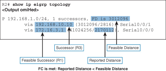
R2 has two routes for 192.168.1.0/24. The first subentry is a route through R3. It is the successor and is installed in the routing table because it has the lowest feasible distance. The second subentry is a route through R1. It is a feasible successor because it meets the feasibility condition which states that the reported distance of the feasible successor must be less than the feasible distance of the successor. The reported distance from R1 is less than the feasible distance of the successor from R3. Therefore, if the successor becomes unavailable, DUAL can immediately install the feasible successor without running any computations.
The show ip eigrp topology all-links command displays all topology table entries, including routes that are not feasible successors, as shown in Figure 21-4.

Like R2, R1 has a successor to 192.168.1.0/24; however, R1 does not have a feasible successor because the route from R2 does not meet the feasibility condition. The reported distance for the route from R2 is greater than the feasible distance of the successor route. Therefore, if the successor becomes unavailable, DUAL must run its algorithm to query neighbors for a potentially better route before it can install the route from R2.
Examining the Routing Table
Verifying that all expected routes are installed in the routing tables is one of the quickest ways to verify that EIGRP is correctly implemented across all routers. Example 21-5 shows the EIGRP routing tables for all three routers.
Example 21-5 EIGRP Routes in the Routing Tables for R1, R2, and R3
R1# show ip route eigrp
172.16.0.0/16 is variably subnetted, 5 subnets, 3 masks
D 172.16.2.0/24 [90/3524096] via 192.168.10.6, 00:24:34, Serial0/0/1
D 192.168.1.0/24 [90/2170112] via 192.168.10.6, 00:24:34, Serial0/0/1
192.168.10.0/24 is variably subnetted, 3 subnets, 2 masks
D 192.168.10.8/30 [90/3523840] via 192.168.10.6, 00:24:34, Serial0/0/1
R1#
R2# show ip route eigrp
172.16.0.0/16 is variably subnetted, 5 subnets, 3 masks
D 172.16.1.0/24 [90/3524096] via 192.168.10.10, 00:25:13, Serial0/0/1
D 192.168.1.0/24 [90/3012096] via 192.168.10.10, 01:02:22, Serial0/0/1
192.168.10.0/24 is variably subnetted, 3 subnets, 2 masks
D 192.168.10.4/30 [90/3523840] via 192.168.10.10, 00:25:19, Serial0/0/1
R2#
R3# show ip route eigrp
172.16.0.0/16 is variably subnetted, 3 subnets, 2 masks
D 172.16.1.0/24 [90/2170112] via 192.168.10.5, 00:25:41, Serial0/0/0
D 172.16.2.0/24 [90/3012096] via 192.168.10.9, 01:02:44, Serial0/0/1
D 172.16.3.0/30 [90/41024000] via 192.168.10.9, 01:02:44, Serial0/0/1
[90/41024000] via 192.168.10.5, 00:25:41, Serial0/0/0
R3#
Modifying the EIGRP for IPv4 Configuration
Like OSPF, the EIGRP configuration can be modified in a number of ways, including enabling automatic summarization, configuring manual summarization, propagating a default route, modifying the bandwidth value, fine-tuning the timers, and configuring MD5 (message digest algorithm 5) authentication.
Automatic Summarization
By default, EIGRP automatic route summarization is disabled. Route summarization allows a router to group networks together and advertises them as one large group using a single summarized route. Figure 21-5 shows an example of how automatic summarization works.
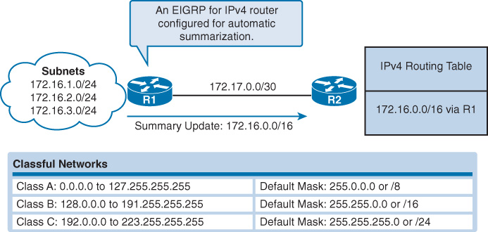
R1 and R2 are both configured using EIGRP for IPv4 with automatic summarization enabled. R1 has three subnets in its routing table: 172.16.1.0/24, 172.16.2.0/24, and 172.16.3.0/24. In the classful network addressing architecture, these subnets are all considered part of a larger Class B network, 172.16.0.0/16. Because EIGRP on R1 is configured for automatic summarization, when it sends its routing update to R2, it summarizes the three /24 subnets as a single network of 172.16.0.0/16, which reduces the number of routing updates sent and the number of entries in R2’s IPv4 routing table.
To enable automatic summarization, configure the command auto-summary in router configuration mode, as shown in Example 21-6.
Example 21-6 Enabling Automatic Summarization
R1(config)# router eigrp 1
R1(config-router)# auto-summary
R2(config)# router eigrp 1
R2(config-router)# auto-summary
R3(config)# router eigrp 1
R3(config-router)# auto-summary
Note
It is probably best to leave automatic summarization disabled because this will ensure that, even when subnets are assigned discontiguously, routing information will still propagate throughout the EIGRP routing domain.
Manual Summarization
With automatic summarization disabled, EIGRP no longer benefits from the smaller routing tables that can result from summarized classful network routes. To control the size of routing tables, you can use manual summarization to specify that a specific interface sends a summary route instead of the individual subnets. This also works for sending supernets.
For example, assume that R3 also has routes to the 192.168.0.0/24, 192.168.2.0/24, and 192.168.3.0/24 networks in addition to the 192.168.1.0/24 LAN. We can simulate these three routes by configuring loopbacks on R3 and then add these networks to the EIGRP configuration on R3, as shown in Example 21-7.
Example 21-7 Simulated LANs on R3
R3(config)# interface loopback 0
R3(config-if)# ip address 192.168.0.1 255.255.255.0
R3(config-if)# interface loopback 2
R3(config-if)# ip address 192.168.2.1 255.255.255.0
R3(config-if)# interface loopback 3
R3(config-if)# ip address 192.168.3.1 255.255.255.0
R3(config-if)# router eigrp 1
R3(config-router)# network 192.168.0.0
R3(config-router)# network 192.168.2.0
R3(config-router)# network 192.168.3.0
R1 and R2 will now have larger routing tables, as shown for R2 in Example 21-8.
Example 21-8 Larger Routing Table on R2
R2# show ip route
<output omitted>
172.16.0.0/16 is variably subnetted, 5 subnets, 3 masks
D 172.16.1.0/24 [90/3524096] via 192.168.10.10, 01:19:25, Serial0/0/1
C 172.16.2.0/24 is directly connected, GigabitEthernet0/0
L 172.16.2.1/32 is directly connected, GigabitEthernet0/0
C 172.16.3.0/30 is directly connected, Serial0/0/0
L 172.16.3.2/32 is directly connected, Serial0/0/0
D 192.168.0.0/24 [90/3139840] via 192.168.10.10, 00:00:25, Serial0/0/1
D 192.168.1.0/24 [90/3012096] via 192.168.10.10, 01:56:34, Serial0/0/1
D 192.168.2.0/24 [90/3139840] via 192.168.10.10, 00:00:20, Serial0/0/1
D 192.168.3.0/24 [90/3139840] via 192.168.10.10, 00:00:16, Serial0/0/1
192.168.10.0/24 is variably subnetted, 3 subnets, 2 masks
D 192.168.10.4/30 [90/3523840] via 192.168.10.10, 01:19:31, Serial0/0/1
C 192.168.10.8/30 is directly connected, Serial0/0/1
L 192.168.10.9/32 is directly connected, Serial0/0/1
209.165.200.0/24 is variably subnetted, 2 subnets, 2 masks
C 209.165.200.224/27 is directly connected, Serial0/1/0
L 209.165.200.225/32 is directly connected, Serial0/1/0
The highlighted routes in Example 21-8 can be summarized into one supernet route advertised by R3 to both R1 and R2. A supernet is a collection of contiguous classful network addresses aggregated into one route. Instead of sending four /24 routes for the classful networks 192.168.0.0, 192.168.1.0, 192.168.2.0, and 192.168.3.0, we can configure a manual summary route as 192.168.0.0/22.
Manual summary routes must be configured on the interface that you want the summary route to be sent out of. The syntax for manual summary routes with EIGRP is as follows:
Router(config-if)# ip summary-address eigrp as-number network-address subnet-mask
Because R3 has two EIGRP neighbors, the EIGRP manual summarization is configured on both serial 0/0/0 and serial 0/0/1, as shown in Example 21-9.
Example 21-9 Configuring Manual Summary Routes for EIGRP
R3(config)# interface serial 0/0/0
R3(config-if)# ip summary-address eigrp 1 192.168.0.0 255.255.252.0
R3(config-if)# interface serial 0/0/1
R3(config-if)# ip summary-address eigrp 1 192.168.0.0 255.255.252.0
R1 and R2 now have smaller routing tables because the four networks are summarized into one route, as highlighted in Example 21-10 for R2.
Example 21-10 Smaller Routing Table for R2
R2# show ip route
<output omitted>
172.16.0.0/16 is variably subnetted, 5 subnets, 3 masks
D 172.16.1.0/24 [90/3524096] via 192.168.10.10, 00:02:12, Serial0/0/1
C 172.16.2.0/24 is directly connected, GigabitEthernet0/0
L 172.16.2.1/32 is directly connected, GigabitEthernet0/0
C 172.16.3.0/30 is directly connected, Serial0/0/0
L 172.16.3.2/32 is directly connected, Serial0/0/0
D 192.168.0.0/22 [90/3012096] via 192.168.10.10, 00:02:12, Serial0/0/1
192.168.10.0/24 is variably subnetted, 3 subnets, 2 masks
D 192.168.10.4/30 [90/3523840] via 192.168.10.10, 00:02:12, Serial0/0/1
C 192.168.10.8/30 is directly connected, Serial0/0/1
L 192.168.10.9/32 is directly connected, Serial0/0/1
209.165.200.0/24 is variably subnetted, 2 subnets, 2 masks
C 209.165.200.224/27 is directly connected, Serial0/1/0
L 209.165.200.225/32 is directly connected, Serial0/1/0
R2#
Propagating an IPv4 Default Route
The “quad zero” default static route can be used with any currently supported routing protocols. In this example, we configure the static default route on R2 because it is connected to the Internet. Example 21-11 shows the default static route configuration on R2.
Example 21-11 Configuring and Redistributing a Default Route in EIGRP
R2(config)# ip route 0.0.0.0 0.0.0.0 Serial0/1/0
R2(config)# router eigrp 1
R2(config-router)# redistribute static
The redistribute static command tells EIGRP to include this static route in its EIGRP updates to other routers. Example 21-12 shows the routing table for R1 with the default route highlighted.
Example 21-12 R1 Routing Table with Default Route Installed
R1# show ip route eigrp
172.16.0.0/16 is variably subnetted, 5 subnets, 3 masks
D 172.16.2.0/24 [90/3524096] via 192.168.10.6, 00:06:27, Serial0/0/1
D 192.168.0.0/22 [90/2170112] via 192.168.10.6, 00:06:28, Serial0/0/1
192.168.10.0/24 is variably subnetted, 3 subnets, 2 masks
D 192.168.10.8/30 [90/3523840] via 192.168.10.6, 00:06:28, Serial0/0/1
D*EX 0.0.0.0/0 [170/8643840] via 192.168.10.6, 00:00:14, Serial0/0/1
R1#
The code D*EX is interpreted as follows:
![]() D: This route was learned through EIGRP.
D: This route was learned through EIGRP.
![]() *: This route is currently the candidate default route.
*: This route is currently the candidate default route.
![]() EX: This route is an external route. Note the administrative distance of 170.
EX: This route is an external route. Note the administrative distance of 170.
Modifying the EIGRP Metric
Because the bandwidth might default to a value that does not reflect the actual value, you can use the bandwidth interface command to modify the bandwidth metric:
Router(config-if)# bandwidth kilobits
In the topology shown in Figure 21-1, notice that the link between R1 and R2 has a bandwidth of 64 kbps, and the link between R2 and R3 has a bandwidth of 1024 kbps. Example 21-13 shows the configurations used on all three routers to modify the bandwidth.
Example 21-13 Modifying the Bandwidth
R1(config)# interface serial 0/0/0
R1(config-if)# bandwidth 64
R2(config)# interface serial 0/0/0
R2(config-if)# bandwidth 64
R2(config-if)# interface serial 0/0/1
R2(config-if)# bandwidth 1024
R3(config)# interface serial 0/0/1
R3(config-if)# bandwidth 1024
Note
The process to modify the bandwidth is the same regardless of whether the interface is configured with IPv4 or IPv6 addressing.
Modifying Hello Intervals and Hold Times
Hello intervals and hold times are configurable on a per-interface basis and do not have to match with other EIGRP routers to establish adjacencies. The syntax for the command to modify the hello interval is as follows:
Router(config-if)# ip hello-interval eigrp as-number seconds
If you change the hello interval, make sure that you also change the hold time to a value equal to or greater than the hello interval. Otherwise, neighbor adjacency will go down after the hold time expires and before the next hello interval. The command to configure a different hold time is as follows:
Router(config-if)# ip hold-time eigrp as-number seconds
The seconds value for both hello and holdtime intervals can range from 1 to 65,535. In Example 21-14, R1 and R2 are configured to use a 60-second hello interval and 180-second hold time.
Example 21-14 Modifying the Hello Intervals and Hold Times
R1(config)# interface s0/0/0
R1(config-if)# ip hello-interval eigrp 1 60
R1(config-if)# ip hold-time eigrp 1 180
R2(config)# interface s0/0/0
R2(config-if)# ip hello-interval eigrp 1 60
R2(config-if)# ip hold-time eigrp 1 180
Authenticating EIGRP Messages
With EIGRP, like OSPF, it is a security best practice to authenticate routing messages. EIGRP supports routing protocol authentication using MD5. The configuration of EIGRP message authentication consists of two steps: the creation of a keychain and key, and the configuration of EIGRP authentication to use that keychain and key.
Step 1 Create a keychain and key.
a. In global configuration mode, create the keychain:
Router(config)# key chain name-of-chain
b. Specify the key ID. The key ID is the number used to identify an authentication key within a keychain. The range of keys is from 0 to 2,147,483,647. It is recommended that the key number be the same on all routers in the configuration:
Router(config-keychain)# key key-id
c. Specify the key string for the key. The key string is similar to a password:
Router(config-keychain-key )# key-string key-string-text
Step 2 Configure EIGRP Authentication Using Keychain and Key
Configure EIGRP to perform message authentication with the previously defined key. Complete this configuration on all interfaces enabled for EIGRP.
a. Enable EIGRP MD5 authentication:
Router(config-if)# ip authentication mode eigrp as-number md5
b. Specify the keychain that should be used for authentication:
Router(config-if)# ip authentication key-chain eigrp as-number name-of-chain
Example 21-15 shows how to configure authentication between the routers in Figure 21-1.
Example 21-15 Enabling EIGRP for IPv4 MD5 Authentication
R1(config)# key chain EIGRP_KEY
R1(config-keychain)# key 1
R1(config-keychain-key)# key-string cisco123
R1(config-keychain-key)# interface serial 0/0/0
R1(config-if)# ip authentication mode eigrp 1 md5
R1(config-if)# ip authentication key-chain eigrp 1 EIGRP_KEY
R1(config-if)# interface serial 0/0/1
R1(config-if)# ip authentication mode eigrp 1 md5
R1(config-if)# ip authentication key-chain eigrp 1 EIGRP_KEY
R1(config-if)# end
R1#
R2(config)# key chain EIGRP_KEY
R2(config-keychain)# key 1
R2(config-keychain-key)# key-string cisco123
R2(config-keychain-key)# interface serial 0/0/0
R2(config-if)# ip authentication mode eigrp 1 md5
R2(config-if)# ip authentication key-chain eigrp 1 EIGRP_KEY
R2(config-if)# interface serial 0/0/1
R2(config-if)# ip authentication mode eigrp 1 md5
R2(config-if)# ip authentication key-chain eigrp 1 EIGRP_KEY
R2(config-if)# end
R2#
R3(config)# key chain EIGRP_KEY
R3(config-keychain)# key 1
R3(config-keychain-key)# key-string cisco123
R3(config-keychain-key)# interface serial 0/0/0
R3(config-if)# ip authentication mode eigrp 1 md5
R3(config-if)# ip authentication key-chain eigrp 1 EIGRP_KEY
R3(config-if)# interface serial 0/0/1
R3(config-if)# ip authentication mode eigrp 1 md5
R3(config-if)# ip authentication key-chain eigrp 1 EIGRP_KEY
R3(config-if)# end
R3#
