
Day 19. Varieties of FHRP
CCNA 200-101 ICND2 Exam Topics
![]() Recognize high availability (FHRP)
Recognize high availability (FHRP)
Key Topics
Most end devices do not store routes to reach remote networks. Instead, they are configured with a default gateway that will handle routing for them. But what if that default gateway fails? To ensure that a device will still have access to remote networks, you should implement some type of default gateway redundancy in the network. That is the role of first hop redundancy protocols (FHRPs). Today’s review covers the choices for providing default gateway redundancy.
First-Hop Redundancy Concepts
FHRPs allow you to install multiple routers in a subnet to collectively act as a single default router. These routers share a virtual IP address, as shown in Figure 19-1.
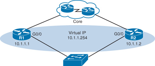
In the figure, the G0/0 interfaces on R1 and R2 are configured with the IP addresses shown. However, both routers are also configured with the virtual IP. This virtual IP address is the default gateway address configured on end devices. A redundancy protocol provides the mechanism for determining which router should take the active role in forwarding traffic. It also determines when the forwarding role must be taken over by a standby router. The transition from one forwarding router to another is transparent to the end devices. It is this ability of a network to dynamically recover from the failure of a device acting as a default gateway that is known as first-hop redundancy.
Regardless of which FHRP is implemented, the steps that take place when the active router fails are as follows:
Step 1 The standby router stops seeing hello messages from the forwarding router.
Step 2 The standby router assumes the role of the forwarding router.
Step 3 Because the new forwarding router assumes both the IP and MAC addresses of the virtual router, the end stations do not recognize a disruption in service.
FHRPs
The following list defines the three options available for first hop redundancy protocols (FHRPs):
![]() Hot Standby Router Protocol (HSRP): A Cisco proprietary FHRP designed to allow for transparent failover of a first-hop IPv4 device. The function of the HSRP standby router is to monitor the operational status of the HSRP group and to quickly assume packet-forwarding responsibility if the active router fails. HSRP for IPv6 provides support for IPv6 networks
Hot Standby Router Protocol (HSRP): A Cisco proprietary FHRP designed to allow for transparent failover of a first-hop IPv4 device. The function of the HSRP standby router is to monitor the operational status of the HSRP group and to quickly assume packet-forwarding responsibility if the active router fails. HSRP for IPv6 provides support for IPv6 networks
![]() Virtual Router Redundancy Protocol (VRRP): An IETF standard that dynamically assigns responsibility for one or more virtual routers to the VRRP routers on an IPv4 LAN. Operation is very similar to HSRP. VRRPv3 supports IPv4 and IPv6.
Virtual Router Redundancy Protocol (VRRP): An IETF standard that dynamically assigns responsibility for one or more virtual routers to the VRRP routers on an IPv4 LAN. Operation is very similar to HSRP. VRRPv3 supports IPv4 and IPv6.
![]() Gateway Load Balancing Protocol (GLBP): Cisco proprietary FHRP that protects data traffic from a failed router or circuit, like HSRP and VRRP, while also allowing load balancing (also called load sharing) between a group of redundant routers. GLBP for IPv6 provides support for IPv6 networks.
Gateway Load Balancing Protocol (GLBP): Cisco proprietary FHRP that protects data traffic from a failed router or circuit, like HSRP and VRRP, while also allowing load balancing (also called load sharing) between a group of redundant routers. GLBP for IPv6 provides support for IPv6 networks.
Because HSRP and VRRP have many similarities, the review today focuses on HSRP and GLBP.
HSRP
HSRP uses an active/standby model where one router actively assumes the role of default gateway for devices on the subnet. One or more routers on the same subnet are then in standby mode. The HSRP active router implements a virtual IP address and matching virtual MAC address. This virtual IP address is part of the HSRP configuration and belongs to the same subnet as the physical interface IP address, but it is a different IP address. The router then automatically creates the virtual MAC address. All the cooperating HSRP routers know these virtual addresses, but only the HSRP active router uses these addresses at any one point in time.
Assume that there are two HSRP routers like R1 and R2 in Figure 19-1. These HSRP routers send each other messages to negotiate which router should be active. Then they continue to send each other messages so that the standby router can detect when the active router fails. If the active router fails, the standby router automatically assumes the virtual IP and MAC addresses, serving as the default gateway for the LAN. The new active router then sends out a gratuitous ARP so that the switches on the subnet will change their MAC address tables to reflect the correct port to reach the virtual MAC. This failover process is transparent to end devices, which are all configured with the virtual IP address as the default gateway.
So, what about load balancing? Aren’t we wasting the capacity of the standby router and the links connecting to it? Yes, if the routers are connected to only one subnet. However if VLANs are configured, the routers can share the load by each serving as active router for some of the VLANs. For example, in Figure 19-2, R1 is the active router for VLAN 10, and R2 is the active router for VLAN 20. Both routers are configured with subinterfaces for inter-VLAN routing and the two virtual IP addresses so that each can assume the role of active router if the other router fails.

Tomorrow‘s review covers HSRP configuration and verification.
GLBP
Cisco developed GLBP to address the need to have better load-balancing capability than just per subnet, as shown in Figure 19-2. GLBP does this by using an active/active model in each subnet.
Like HSRP, GLBP uses a virtual IP address so that failovers are transparent to end devices. However, each GLBP router is assigned a different virtual MAC address so that the active virtual gateway (AVG) router can alternate between MACs when replying to ARP requests. Referring back to Figure 19-2, assume that PC1 sends an Address Resolution Protocol (ARP) request to discover its default gateway. R1 would reply with the virtual MAC address assigned to itself. Later, PC2 sends an ARP request, and R1 then replies with the virtual MAC address assigned to R2. Therefore, PC1 would send all nonlocal traffic to R1, and PC2 would send all nonlocal traffic to R2.
If the difference between HSRP load balancing and GLBP is not immediately clear, consider a scenario in Figure 19-2 where VLAN 10 has 10 hosts connected and VLAN 20 has 20 hosts connected. With HSRP load balancing, R2 would handle twice as much traffic as R1—assuming traffic patterns are similar from all end devices. With GLBP, the AVG will send ARP replies to each end device, alternating between the two virtual MACs so that load balancing is more efficient.
Tomorrow’s review covers GLBP configuration and verification.
Study Resources
For today’s exam topics, refer to the following resources for more study.
