Day 1. CCNA Skills Review and Practice
Key Topics
Tomorrow you take the CCNA exam. Therefore, today you should take the time to do some relaxed skimming of all the previous days’ topics focusing on areas where you are still weak. If you have access to a timed practice test like the ones available in Wendell Odom’s books, use these to help isolate areas in which you might need a little further study.
Included as part of this book is a CCNA Skills Practice that covers most of the CCNA configuration skills in one topology. This scenario should help you quickly review many of the commands covered by the CCNA.
CCNA Skills Practice
This practice example includes many skills from CCENT exam topics and a good sampling of skills from the CCNA exam topics.
Introduction
In this comprehensive CCNA skills activity, the XYZ Corporation uses a combination of Frame Relay and PPP for WAN connections. The HQ router provides access to the server farm and the Internet through Network Address Translation (NAT). HQ also uses a basic firewall access control list (ACL) to filter inbound traffic. B1 is configured for inter-VLAN routing and Dynamic Host Configuration Protocol (DHCP). The switches attached to B1 are configured with port security, virtual LANs (VLANs), VLAN Trunking Protocol (VTP), and Spanning Tree Protocol (STP). Routing is achieved through EIGRP and static and default routes. Your job is to successfully implement all these technologies, leveraging what you have learned during your CCNA studies.
You are responsible for configuring HQ and the branch routers B1, B2, and B3. Assume that routers and switches under your administration have no configuration.
Topology Diagram
Figure 1-1 shows the topology for this CCNA Skills Review.
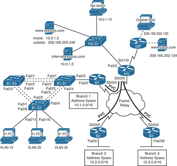
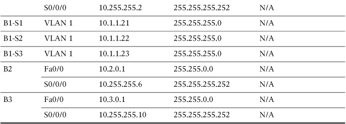
Addressing Table
Table 1-1 shows the addressing scheme for the network shown in Figure 1-1.

VLAN Configuration and Port Mappings
Table 1-2 shows the VLAN configuration information for the B1-S2 switch, including names, subnets, and port mappings.

ISP Configuration
If you choose to configure this network on real equipment or a network simulator, use the script in Example 1-1 to configure ISP.
hostname ISP
!
username HQ password ciscochap
!
interface FastEthernet0/0
description Link to Outside Host
ip address 209.165.202.129 255.255.255.252
no shutdown
!
interface FastEthernet0/1
description Link to Cisco web server
ip address 209.165.202.133 255.255.255.252
no shutdown
!
interface Serial0/0/0
ip address 209.165.201.2 255.255.255.252
encapsulation ppp
ppp authentication chap
clock rate 64000
no shutdown
!
ip route 209.165.200.240 255.255.255.248 Serial0/0/0
!
end
copy run start
Task 1: Configure Frame Relay in a Hub-and-Spoke Topology
Step 1 Configure the Frame Relay core.
Use Table 1-1 and the following requirements:
![]() HQ is the hub router. B1, B2, and B3 are the spokes.
HQ is the hub router. B1, B2, and B3 are the spokes.
![]() HQ uses a point-to-point subinterface for each of the Branch routers.
HQ uses a point-to-point subinterface for each of the Branch routers.
![]() B3 must be manually configured to use IETF encapsulation.
B3 must be manually configured to use IETF encapsulation.
![]() The LMI type must be manually configured as Q933A for HQ, B1, and B2. B3 uses ANSI.
The LMI type must be manually configured as Q933A for HQ, B1, and B2. B3 uses ANSI.
Step 2 Configure the LAN interface on HQ.
Step 3 Verify that HQ can ping each of the branch routers.
Task 2: Configure PPP with CHAP
Step 1 Configure the WAN link from HQ to ISP using PPP encapsulation and CHAP authentication.
The CHAP password is ciscochap.
Step 2 Verify that HQ can ping ISP.
Use the following requirements:
![]() Allow all addresses for the 10.0.0.0/8 address space to be translated.
Allow all addresses for the 10.0.0.0/8 address space to be translated.
![]() XYZ Corporation owns the 209.165.200.240/29 address space. The pool, XYZCORP, uses addresses .241 through .245 with a /29 mask.
XYZ Corporation owns the 209.165.200.240/29 address space. The pool, XYZCORP, uses addresses .241 through .245 with a /29 mask.
![]() The www.xyzcorp.com website at 10.0.1.2 is registered with the public DNS system at IP address 209.165.200.246.
The www.xyzcorp.com website at 10.0.1.2 is registered with the public DNS system at IP address 209.165.200.246.
Step 2 Verify that NAT is operating by using extended ping.
From HQ, ping the serial 0/0/0 interface on ISP using the HQ LAN interface as the source address. This ping should succeed.
Verify that NAT translated the ping with the show ip nat translations command.
Task 4: Configure Default Routing
Step 1 Configure HQ with a default route to ISP.
Use the exit interface as an argument.
Step 2 Verify connectivity beyond ISP.
The NetAdmin PC should be able to ping the www.cisco.com web server.
Task 5: Configure Inter-VLAN Routing
Step 1 Configure B1 for inter-VLAN routing.
Using the addressing table B1, configure and activate the LAN interface for inter-VLAN routing.
Step 2 Verify routing tables.
B1 should now have six directly connected networks and one static default route.
Task 6: Configure and Optimize EIGRP Routing
Step 1 Configure HQ, B1, B2, and B3 with EIGRP.
![]() Use autonomous system 100.
Use autonomous system 100.
![]() HQ should redistribute its default route to the branch routers.
HQ should redistribute its default route to the branch routers.
![]() Manually summarize EIGRP routes so that B1 advertises the 10.1.0.0/16 address space only to HQ.
Manually summarize EIGRP routes so that B1 advertises the 10.1.0.0/16 address space only to HQ.
Step 2 Verify routing tables and connectivity.
HQ and the branch routers should now have complete routing tables.
The NetAdmin PC should now be able to ping each LAN interface and the VLAN subinterfaces on B1.
Task 7: Configure VTP, Trunking, the VLAN Interface, and VLANs
Note
VTP is not a topic on the CCENT or CCNA exam. If you do not know how to configure VTP, you can skip it and configure VLANs on each router or refer to the answers in the next section.
Step 1 Configure the B1 switches with VTP.
![]() B1-S1 is the VTP server. B1-S2 and B1-S3 are VTP clients.
B1-S1 is the VTP server. B1-S2 and B1-S3 are VTP clients.
![]() The domain name is XYZCORP.
The domain name is XYZCORP.
![]() The password is xyzvtp.
The password is xyzvtp.
Step 2 Configure trunking.
Configure the appropriate interfaces in trunking mode.
Step 3 Configure the VLAN interface and default gateway on B1-S1, B1-S2, and B1-S3.
Step 4 Create the VLANs on B1-S1.
Create and name the VLANs listed in Table 1-2 on B1-S1 only. VTP advertises the new VLANs to B1-S2 and B1-S3.
Step 5 Verify that VLANs have been sent to B1-S2 and B1-S3.
Task 8: Assign VLANs and Configure Port Security
Step 1 Assign VLANs to the access ports on B1-S2.
Use Table 1-2 to complete the following requirements:
![]() Configure access ports.
Configure access ports.
![]() Assign VLANs to the access ports.
Assign VLANs to the access ports.
Step 2 Configure port security.
Use the following policy to establish port security on the B1-S2 access ports:
![]() Allow only one MAC address.
Allow only one MAC address.
![]() Configure the first learned MAC address to “stick” to the configuration.
Configure the first learned MAC address to “stick” to the configuration.
![]() Set the port to shut down if a security violation occurs.
Set the port to shut down if a security violation occurs.
Step 3 Verify VLAN assignments and port security.
Use the appropriate commands to verify that access VLANs are correctly assigned and that the port security policy has been enabled.
Task 9: Configure STP
Step 1 Configure B1-S1 as the root bridge.
Set the priority level to 4096 on B1-S1 so that this switch is always the root bridge for all VLANs.
Step 2 Configure B1-S3 as the backup root bridge.
Set the priority level to 8192 on B1-S3 so that this switch is always the backup root bridge for all VLANs.
Step 3 Verify that B1-S1 is the root bridge.
Task 10: Configure DHCP
Step 1 Configure DHCP pools for each VLAN.
On B1, configure DHCP pools for each VLAN using the following requirements:
![]() Exclude the first ten IP addresses in each pool for the LANs.
Exclude the first ten IP addresses in each pool for the LANs.
![]() The pool name is B1_VLAN##, where ## is the VLAN number.
The pool name is B1_VLAN##, where ## is the VLAN number.
![]() The internal.xyzcorp.com server provides DNS services to XYZ Corporation. Include the DNS server as part of the DHCP configuration.
The internal.xyzcorp.com server provides DNS services to XYZ Corporation. Include the DNS server as part of the DHCP configuration.
Step 2 Verify that the PCs have an IP address.
Step 3 Verify connectivity.
All PCs physically attached to the network should be able to ping the www.cisco.com web server.
Task 11: Configure a Firewall ACL
Step 1 Verify connectivity from Outside Host.
The Outside Host PC should be able to ping the server at www.xyzcorp.com.
Step 2 Implement a basic firewall ACL.
Because ISP represents connectivity to the Internet, configure a named ACL called FIREWALL on HQ in the following order:
a. Allow inbound HTTP requests to the www.xyzcorp.com server.
b. Allow only established TCP sessions from ISP and any source beyond ISP.
c. Allow only inbound ping replies from ISP and any source beyond ISP.
d. Explicitly block all other inbound access from ISP and any source beyond ISP.
Step 3 Verify connectivity from Outside Host.
The Outside Host PC should not be able to ping the server at www.xyzcorp.com. However, the Outside Host PC should be able to request a web page.
CCNA Skills Practice (Answers)
The following are the scripts and verification commands you would enter for each of the tasks.
Task 1: Configure Frame Relay in a Hub-and-Spoke Topology
Step 1 Configure the Frame Relay core.
!-----------
!HQ
!-----------
enable
configure terminal
host HQ
!
interface Serial0/0/0
no ip address
encapsulation frame-relay
frame-relay lmi-type q933a
no shutdown
!
interface Serial0/0/0.41 point-to-point
ip address 10.255.255.1 255.255.255.252
frame-relay interface-dlci 41
!
interface Serial0/0/0.42 point-to-point
ip address 10.255.255.5 255.255.255.252
frame-relay interface-dlci 42
!
interface Serial0/0/0.43 point-to-point
ip address 10.255.255.9 255.255.255.252
frame-relay interface-dlci 43
end
copy run start
!-----------
!B1
!-----------
enable
configure terminal
host B1
!
interface Serial0/0/0
ip address 10.255.255.2 255.255.255.252
encapsulation frame-relay
frame-relay lmi-type q933a
no shutdown
end
copy run start
!-----------
!B2
!-----------
enable
configure terminal
host B2
!
interface Serial0/0/0
ip address 10.255.255.6 255.255.255.252
encapsulation frame-relay
frame-relay lmi-type q933a
no shutdown
end
copy run start
!-----------
!B3
!-----------
enable
configure terminal
host B3
!
interface Serial0/0/0
ip address 10.255.255.10 255.255.255.252
encapsulation frame-relay ietf
frame-relay lmi-type ansi
no shutdown
end
copy run start
Step 2 Configure the LAN interface on HQ.
!
interface FastEthernet0/0
description Server Farm
ip address 10.0.1.1 255.255.255.0
no shutdown
!
Step 3 Verify that HQ can ping each of the Branch routers.
HQ# ping 10.255.255.2
Type escape sequence to abort.
Sending 5, 100-byte ICMP Echos to 10.255.255.2, timeout is 2 seconds:
!!!!!
Success rate is 100 percent (5/5), round-trip min/avg/max = 40/71/89 ms
HQ# ping 10.255.255.6
Type escape sequence to abort.
Sending 5, 100-byte ICMP Echos to 10.255.255.6, timeout is 2 seconds:
!!!!!
Success rate is 100 percent (5/5), round-trip min/avg/max = 35/60/69 ms
HQ# ping 10.255.255.10
Type escape sequence to abort.
Sending 5, 100-byte ICMP Echos to 10.255.255.10, timeout is 2 seconds:
!!!!!
Success rate is 100 percent (5/5), round-trip min/avg/max = 23/58/87 ms
Task 2: Configure PPP with CHAP
Step 1 Configure the WAN link from HQ to ISP using PPP encapsulation and CHAP authentication.
The CHAP password is ciscochap.
username ISP password ciscochap
interface Serial0/1/0
description Link to ISP
ip address 209.165.201.1 255.255.255.252
encapsulation ppp
ppp authentication chap
no shutdown
Step 2 Verify that HQ can ping ISP.
HQ# ping 209.165.201.2
Type escape sequence to abort.
Sending 5, 100-byte ICMP Echos to 209.165.201.2, timeout is 2 seconds:
!!!!!
Success rate is 100 percent (5/5), round-trip min/avg/max = 17/30/38 ms
Use the following requirements:
ip access-list standard NAT_LIST
permit 10.0.0.0 0.255.255.255
!
ip nat pool XYZCORP 209.165.200.241 209.165.200.245 netmask 255.255.255.248
ip nat inside source list NAT_LIST pool XYZCORP overload
ip nat inside source static 10.0.1.2 209.165.200.246
!
interface fa0/0
ip nat inside
interface s0/0/0.41 point-to-point
ip nat inside
interface s0/0/0.42 point-to-point
ip nat inside
interface s0/0/0.43 point-to-point
ip nat inside
interface s0/1/0
ip nat outside
Step 2 Verify that NAT is operating by using extended ping.
HQ# ping
Protocol [ip]:
Target IP address: 209.165.201.2
Repeat count [5]:
Datagram size [100]:
Timeout in seconds [2]:
Extended commands [n]: y
Source address or interface: 10.0.1.1
Type of service [0]:
Set DF bit in IP header? [no]:
Validate reply data? [no]:
Data pattern [0xABCD]:
Loose, Strict, Record, Timestamp, Verbose[none]:
Sweep range of sizes [n]:
Type escape sequence to abort.
Sending 5, 100-byte ICMP Echos to 209.165.201.2, timeout is 2 seconds:
Packet sent with a source address of 10.0.1.1
!!!!!
Success rate is 100 percent (5/5), round-trip min/avg/max = 18/34/42 ms
Verify that NAT translated the ping with the show ip nat translations command.
HQ# show ip nat translations
Pro Inside global Inside local Outside local Outside global
icmp 209.165.200.241:3510.0.1.1:35 209.165.201.2:35 209.165.201.2:35
icmp 209.165.200.241:3610.0.1.1:36 209.165.201.2:36 209.165.201.2:36
icmp 209.165.200.241:3710.0.1.1:37 209.165.201.2:37 209.165.201.2:37
icmp 209.165.200.241:3810.0.1.1:38 209.165.201.2:38 209.165.201.2:38
icmp 209.165.200.241:3910.0.1.1:39 209.165.201.2:39 209.165.201.2:39
--- 209.165.200.246 10.0.1.2 --- ---
Task 4: Configure Default Routing
Step 1 Configure HQ with a default route to ISP.
ip route 0.0.0.0 0.0.0.0 Serial0/1/0
Step 2 Verify connectivity beyond ISP.
!From NetAdmin
C:> ping 209.165.202.134
Pinging 209.165.202.134 with 32 bytes of data:
Reply from 209.165.202.134: bytes=32 time=12ms TTL=126
Reply from 209.165.202.134: bytes=32 time=188ms TTL=126
Reply from 209.165.202.134: bytes=32 time=8ms TTL=126
Reply from 209.165.202.134: bytes=32 time=8ms TTL=126
Ping statistics for 209.165.202.134:
Packets: Sent = 4, Received = 4, Lost = 0 (0% loss),
Approximate round trip times in milli-seconds:
Minimum = 8ms, Maximum = 188ms, Average = 54ms
Task 5: Configure Inter-VLAN Routing
Step 1 Configure B1 for inter-VLAN routing.
!
interface FastEthernet0/0
no shutdown
!
interface FastEthernet0/0.1
description Mgmt&Native VLAN 1
encapsulation dot1Q 1 native
ip address 10.1.1.1 255.255.255.0
!
interface FastEthernet0/0.10
description Admin VLAN 10
encapsulation dot1Q 10
ip address 10.1.10.1 255.255.255.0
!
interface FastEthernet0/0.20
description Sales VLAN 20
encapsulation dot1Q 20
ip address 10.1.20.1 255.255.255.0
!
interface FastEthernet0/0.30
description Production VLAN 30
encapsulation dot1Q 30
ip address 10.1.30.1 255.255.255.0
!
Step 2 Verify routing tables.
B1# show ip route
<output omitted>
Gateway of last resort is not set
10.0.0.0/8 is variably subnetted, 5 subnets, 2 masks
C 10.1.1.0/24 is directly connected, FastEthernet0/0.1
C 10.1.10.0/24 is directly connected, FastEthernet0/0.10
C 10.1.20.0/24 is directly connected, FastEthernet0/0.20
C 10.1.30.0/24 is directly connected, FastEthernet0/0.30
C 10.255.255.0/30 is directly connected, Serial0/0/0
Task 6: Configure and Optimize EIGRP Routing
Step 1 Configure HQ, B1, B2, and B3 with EIGRP.
!-----------------
!All Routers
!-----------------
router eigrp 100
network 10.0.0.0
no auto-summary
!
!On HQ...
redistribute static
!
!On B1...
interface serial 0/0/0
ip summary-address eigrp 10.1.0.0.0 255.255.0.0
Step 2 Verify routing tables and connectivity.
!
HQ# show ip route
<output omitted>
Gateway of last resort is 0.0.0.0 to network 0.0.0.0
10.0.0.0/8 is variably subnetted, 7 subnets, 3 masks
C 10.0.1.0/24 is directly connected, FastEthernet0/0
D 10.1.0.0/16 [90/2681856] via 10.255.255.2, 00:29:42,
Serial0/0/0.41
D 10.2.0.0/16 [90/2172416] via 10.255.255.6, 00:29:40,
Serial0/0/0.42
D 10.3.0.0/16 [90/2172416] via 10.255.255.10, 00:29:40,
Serial0/0/0.43
C 10.255.255.0/30 is directly connected, Serial0/0/0.41
C 10.255.255.4/30 is directly connected, Serial0/0/0.42
C 10.255.255.8/30 is directly connected, Serial0/0/0.43
209.165.201.0/30 is subnetted, 1 subnets
C 209.165.201.0 is directly connected, Serial0/1/0
S* 0.0.0.0/0 is directly connected, Serial0/1/0
HQ#
!Pings are shown for one LAN interface per branch router
!From NetAdmin PC
C:> ping 10.1.10.1
Pinging 10.1.10.1 with 32 bytes of data:
Reply from 10.1.10.1: bytes=32 time=104ms TTL=254
Reply from 10.1.10.1: bytes=32 time=104ms TTL=254
Reply from 10.1.10.1: bytes=32 time=100ms TTL=254
Reply from 10.1.10.1: bytes=32 time=132ms TTL=254
Ping statistics for 10.1.10.1:
Packets: Sent = 4, Received = 4, Lost = 0 (0% loss),
Approximate round trip times in milli-seconds:
Minimum = 100ms, Maximum = 132ms, Average = 110ms
C:> ping 10.2.0.1
Pinging 10.2.0.1 with 32 bytes of data:
Reply from 10.2.0.1: bytes=32 time=83ms TTL=254
Reply from 10.2.0.1: bytes=32 time=152ms TTL=254
Reply from 10.2.0.1: bytes=32 time=118ms TTL=254
Reply from 10.2.0.1: bytes=32 time=103ms TTL=254
Ping statistics for 10.2.0.1:
Packets: Sent = 4, Received = 4, Lost = 0 (0% loss),
Approximate round trip times in milli-seconds:
Minimum = 83ms, Maximum = 152ms, Average = 114ms
C:> ping 10.3.0.1
Pinging 10.3.0.1 with 32 bytes of data:
Reply from 10.3.0.1: bytes=32 time=114ms TTL=254
Reply from 10.3.0.1: bytes=32 time=99ms TTL=254
Reply from 10.3.0.1: bytes=32 time=108ms TTL=254
Reply from 10.3.0.1: bytes=32 time=153ms TTL=254
Ping statistics for 10.3.0.1:
Packets: Sent = 4, Received = 4, Lost = 0 (0% loss),
Approximate round trip times in milli-seconds:
Minimum = 99ms, Maximum = 153ms, Average = 118ms
Task 7: Configure VTP, Trunking, the VLAN Interface, and VLANs
Step 1 Configure the B1 switches with VTP.
Step 2 Configure trunking.
Configure the appropriate interfaces in trunking mode.
Step 3 Configure the VLAN interface and default gateway on B1-S1, B1-S2, and B1-S3.
Step 4 Create the VLANs on B1-S1.
!
!-----------
!S1
!-----------
enable
configure terminal
host B1-S1
!
vtp mode server
vtp domain XYZCORP
vtp password xyzvtp
!
interface range Fa0/1 – Fa0/5
switchport mode trunk
!
interface vlan 1
ip address 10.1.1.21 255.255.255.0
no shut
ip default-gateway 10.1.1.1
!
vlan 10
name Admin
vlan 20
name Sales
vlan 30
name Production
end
copy run start
!-----------
!S2
!-----------
enable
configure terminal
host B1-S2
!
vtp mode client
vtp domain XYZCORP
vtp password xyzvtp
!
interface range Fa0/1 – Fa0/4
switchport mode trunk
!
!
interface vlan 1
ip address 10.1.1.22 255.255.255.0
no shut
ip default-gateway 10.1.1.1
!
end
copy run start
!-----------
!S3
!-----------
enable
configure terminal
host B1-S3
!
vtp mode client
vtp domain XYZCORP
vtp password xyzvtp
!
interface range Fa0/1 – Fa0/5
switchport mode trunk
!
interface vlan 1
ip address 10.1.1.23 255.255.255.0
no shut
ip default-gateway 10.1.1.1
!
end
copy run start
Step 5 Verify that VLANs have been sent to B1-S2 and B1-S3.
!Output for B1-S2 is shown. Should be similar on B1-S3
B1-S2# show vtp status
VTP Version : 2
Configuration Revision : 0
Maximum VLANs supported locally : 64
Number of existing VLANs : 8
VTP Operating Mode : Client
VTP Domain Name : XYZCORP
VTP Pruning Mode : Disabled
VTP V2 Mode : Disabled
VTP Traps Generation : Disabled
MD5 digest : 0xCD 0xBF 0xDE 0x4E 0x0F 0x79 0x7D 0x3E
Configuration last modified by 10.1.1.21 at 3-1-93 00:43:41
B1-S2# show vlan brief
VLAN Name Status Ports
---- -------------------------- --------- ------------------------------
1 default active Fa0/5, Fa0/6, Fa0/7, Fa0/8
Fa0/9, Fa0/10, Fa0/11, Fa0/12
Fa0/13, Fa0/14, Fa0/15, Fa0/16
Fa0/17, Fa0/18, Fa0/19, Fa0/20
Fa0/21, Fa0/22, Fa0/23, Fa0/24
Gig1/1, Gig1/2
10 Admin active
20 Sales active
30 Production active
1002 fddi-default active
1003 token-ring-default active
1004 fddinet-default active
1005 trnet-default active
Task 8: Assign VLANs and Configure Port Security
Step 1 Assign VLANs to the access ports on B1-S2.
interface fa0/6 – fa0/10
switchport access vlan 10
interface fa0/11 – fa0/15
switchport access vlan 20
interface fa0/16 – fa0/20
switchport access vlan 10
Step 2 Configure port security.
interface fa0/6 – fa0/20
switchport port-security
switchport port-security maximum 1
switchport port-security mac-address sticky
switchport port-security violation shutdown
Step 3 Verify VLAN assignments and port security.
B1-S2# show vlan brief
VLAN Name Status Ports
---- --------------------------- --------- -------------------------------
1 default active Fa0/5, Fa0/21, Fa0/22, Fa0/23
Fa0/24, Gig1/1, Gig1/2
10 Admin active Fa0/6, Fa0/7, Fa0/8, Fa0/9
Fa0/10
20 Sales active Fa0/11, Fa0/12, Fa0/13, Fa0/14
Fa0/15
30 Production active Fa0/16, Fa0/17, Fa0/18, Fa0/19
Fa0/20
1002 fddi-default active
1003 token-ring-default active
1004 fddinet-default active
1005 trnet-default active
!
B1-S2# show port-security interface fa0/6
Port Security : Enabled
Port Status : Secure-up
Violation Mode : Shutdown
Aging Time : 0 mins
Aging Type : Absolute
SecureStatic Address Aging : Disabled
Maximum MAC Addresses : 1
Total MAC Addresses : 1
Configured MAC Addresses : 0
Sticky MAC Addresses : 1
Last Source Address:Vlan : 00D0.BCCA.9C3A:10
Security Violation Count : 0
Task 9: Configure STP
Step 1 Configure B1-S1 as the root bridge.
!
spanning-tree vlan 1 priority 4096
spanning-tree vlan 10 priority 4096
spanning-tree vlan 20 priority 4096
spanning-tree vlan 30 priority 4096
!
Step 2 Configure B1-S3 as the backup root bridge.
!
spanning-tree vlan 1 priority 8192
spanning-tree vlan 10 priority 8192
spanning-tree vlan 20 priority 8192
spanning-tree vlan 30 priority 8192
!
Step 3 Verify that B1-S1 is the root bridge.
!Output should be similar for all VLANs.
B1-S1# show spanning-tree vlan 10
VLAN0010
Spanning tree enabled protocol ieee
Root ID Priority 4106
Address 00D0.BA3D.2C94
This bridge is the root
Hello Time 2 sec Max Age 20 sec Forward Delay 15 sec
Bridge ID Priority 4106 (priority 4096 sys-id-ext 10)
Address 00D0.BA3D.2C94
Hello Time 2 sec Max Age 20 sec Forward Delay 15 sec
Aging Time 20
Interface Role Sts Cost Prio.Nbr Type
---------------- ---- --- ------ -------- -----------------------------
Fa0/2 Desg FWD 19 128.2 P2p
Fa0/1 Desg FWD 19 128.1 P2p
Fa0/5 Desg FWD 19 128.5 P2p
Fa0/4 Desg FWD 19 128.4 P2p
Fa0/3 Desg FWD 19 128.3 P2p
Task 10: Configure DHCP
Step 1 Configure DHCP pools for each VLAN.
!
ip dhcp excluded-address 10.1.10.1 10.1.10.10
ip dhcp excluded-address 10.1.20.1 10.1.20.10
ip dhcp excluded-address 10.1.30.1 10.1.30.10
!
ip dhcp pool B1_VLAN10
network 10.1.10.0 255.255.255.0
default-router 10.1.10.1
dns-server 10.0.1.4
ip dhcp pool B1_VLAN20
network 10.1.20.0 255.255.255.0
default-router 10.1.20.1
dns-server 10.0.1.4
ip dhcp pool B1_VLAN30
network 10.1.30.0 255.255.255.0
default-router 10.1.30.1
dns-server 10.0.1.4
!
Step 2 Verify that the PCs have an IP address.
Use ipconfig on each PC to verify DHCP is working correctly. You might have to set the PC to automatically obtain an IP address and then use ipconfig/release and ipconfig/renew to obtain the IP address.
Step 3 Verify connectivity.
!From B1-PC1
C:> ping 209.165.202.134
Pinging 209.165.202.134 with 32 bytes of data:
Reply from 209.165.202.134: bytes=32 time=234ms TTL=125
Reply from 209.165.202.134: bytes=32 time=184ms TTL=125
Reply from 209.165.202.134: bytes=32 time=230ms TTL=125
Reply from 209.165.202.134: bytes=32 time=228ms TTL=125
Ping statistics for 209.165.202.134:
Packets: Sent = 4, Received = 4, Lost = 0 (0% loss),
Approximate round trip times in milli-seconds:
Minimum = 184ms, Maximum = 234ms, Average = 219ms
Task 11: Configure a Firewall ACL
Step 1 Verify connectivity from Outside Host.
!-----------
!Outside Host
!-----------
!
C:> ping www.xyzcorp.com
Pinging 209.165.200.246 with 32 bytes of data:
Reply from 209.165.200.246: bytes=32 time=45ms TTL=126
Reply from 209.165.200.246: bytes=32 time=115ms TTL=126
Reply from 209.165.200.246: bytes=32 time=124ms TTL=126
Reply from 209.165.200.246: bytes=32 time=101ms TTL=126
Ping statistics for 209.165.200.246:
Packets: Sent = 4, Received = 4, Lost = 0 (0% loss),
Approximate round trip times in milli-seconds:
Minimum = 45ms, Maximum = 124ms, Average = 96ms
!
Step 2 Implement a basic firewall ACL.
!-----------
!HQ
!-----------
ip access-list extended FIREWALL
permit tcp any host 209.165.200.246 eq www
permit tcp any any established
permit icmp any any echo-reply
deny ip any any
!
interface Serial0/1/0
ip access-group FIREWALL in
!
Step 3 Verify connectivity from Outside Host.
The Outside Host PC should not be able to ping the server at www.xyzcorp.com. However, the Outside Host PC should be able to request a web page.
!-----------
!Outside Host
!-----------
!
C:> ping www.xyzcorp.com
Pinging 209.165.200.246 with 32 bytes of data:
Request timed out.
Request timed out.
Request timed out.
Request timed out.
Ping statistics for 209.165.200.246:
Packets: Sent = 4, Received = 0, Lost = 4 (100% loss),
!
CCNA Skills Challenge
For an extra challenge, try the following modifications to the CCNA Skills Practice:
![]() Implement dual-stack with IPv6.
Implement dual-stack with IPv6.
![]() Change the routing protocol to OSPF.
Change the routing protocol to OSPF.
![]() Make up some different host requirements and change the addressing scheme.
Make up some different host requirements and change the addressing scheme.
![]() Configure the network with all static routes. No routing protocol.
Configure the network with all static routes. No routing protocol.
![]() Change the encapsulation type from Frame Relay to PPP and verify functionality.
Change the encapsulation type from Frame Relay to PPP and verify functionality.
![]() Add switches to B2 and B3 with similar VLAN configurations as used on B1 switches.
Add switches to B2 and B3 with similar VLAN configurations as used on B1 switches.
![]() Add a new branch router through a T1 link. Assume that the new branch router is not a Cisco router. You must use PPP with PAP authentication.
Add a new branch router through a T1 link. Assume that the new branch router is not a Cisco router. You must use PPP with PAP authentication.
![]() Implement some of your own security policies by configuring more access lists.
Implement some of your own security policies by configuring more access lists.
![]() Configure SSH.
Configure SSH.
![]() If you have a friend you are studying with, take turns introducing errors to the network. Then practice using show and debug commands to verify and troubleshoot the network.
If you have a friend you are studying with, take turns introducing errors to the network. Then practice using show and debug commands to verify and troubleshoot the network.