Day 4. PPPoE
CCNA 200-101 ICND2 Exam Topics
![]() Implement and troubleshoot PPPoE
Implement and troubleshoot PPPoE
Key Topics
Today’s review covers concepts and configurations of PPP over Ethernet (PPPoE), which is a technology used with digital subscriber line (DSL) to provide Internet service providers (ISPs) a way to track and authenticate customers.
PPPoE Concepts
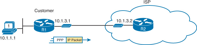
PPP can be used on all serial links, including those links created with dialup analog and ISDN modems. To this day, the link from a dialup user to an ISP, using analog modems, likely uses PPP, as shown in Figure 4-1.
In addition, ISPs often use PPP as the data-link protocol over broadband connections for the following reasons:
![]() The ability to assign IP addresses to remote ends of a PPP link
The ability to assign IP addresses to remote ends of a PPP link
![]() Support for Challenge Handshake Authentication Protocol (CHAP) to authenticate customers, allowing ISPs to also check accounting records before authorizing access
Support for Challenge Handshake Authentication Protocol (CHAP) to authenticate customers, allowing ISPs to also check accounting records before authorizing access
Technologies came to market in the following order, with varying support for PPP:
1. Analog modems for dialup that could use PPP and CHAP
2. ISDN for dialup that could use PPP and CHAP
3. DSL, which did not create a point-to-point link and could not support PPP and CHAP
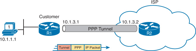
PPPoE was developed because Ethernet links do not natively support PPP. As shown in Figure 4-2, PPPoE allows the sending of PPP frames encapsulated inside Ethernet frames.
PPPoE Configuration
To implement PPPoE, complete the following steps:
Step 1 Create a PPP tunnel using a dialer interface, which is a type of virtual interface. Configure PPP and addressing on the dialer interface. Addressing is usually automatically assigned by ISP.
Step 2 Configure PPP CHAP to authentication with the ISP.
Step 3 Enable PPPoE on the physical interface with the pppoe enable command. The dialer interface is linked to the Ethernet interface with the pppoe-client command followed by the number used to create the dialer pool in Step 2. The dialer interface number does not have to match the dialer pool number.
Step 4 The maximum transmission unit (MTU) should be set down to 1492, versus the default of 1500, to accommodate the PPPoE headers.
Example 4-1 shows how to configure and verify PPPoE on R1.
Example 4-1 Configuring and Verifying PPPoE
R1(config)# interface dialer 5
R1(config-if)# encapsulation ppp
R1(config-if)# ip address negotiated
R1(config-if)# ip mtu 1492
R1(config-if)# dialer pool 5
R1(config-if)# ppp chap hostname customer2222
R1(config-if)# ppp chap password ConnectMe
R1(config-if)# no shutdown
R1(config-if)# interface GigabitEthernet 0/0
R1(config-if)# no ip address
R1(config-if)# pppoe enable
R1(config-if)# pppoe-client dial-pool-number 5
R1(config-if)# no shutdown
R1(config-if)# end
R1# show ip interface brief
Interface IP-Address OK? Method Status Protocol
GigabitEthernet0/0 unassigned YES NVRAM up up
GigabitEthernet0/1 172.16.1.1 YES manual up up
Dialer5 64.100.10.1 YES manual up up
Virtual-Access1 unassigned YES unset up up
Note
Scott Empson’s CCNA Routing and Switching Portable Command Guide, Third Edition, includes a different PPPoE configuration example.
Study Resources
For today’s exam topics, refer to the following resources for more study.