Day 31. Spanning Tree Protocols
CCNA 200-101 ICND2 Exam Topics
![]() Identify enhanced switching technologies
Identify enhanced switching technologies
Key Topics
Part I focuses on switching technologies, including Spanning Tree Protocol (STP), EtherChannel, and first-hop redundancy protocols (FHRPs). Today’s review covers STP and its variations, standards that allow for redundant switched networks without worrying about switching loops.
STP Concepts and Operation
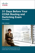
One of the key characteristics of a well-built communications network is its resiliency. This means that the network needs to be able to handle a device or link failure through redundancy. A redundant topology can eliminate a single point of failure by using multiple links, multiple devices, or both. Spanning Tree Protocol (STP) helps to prevent loops in a redundant switched network. Figure 31-1 shows an example of a three-layer topology (core, distribution, access) with redundant links.
Without STP, redundancy in the switched network could introduce the following issues:
![]() Broadcast storms: Each switch floods broadcasts endlessly, called a broadcast storm.
Broadcast storms: Each switch floods broadcasts endlessly, called a broadcast storm.
![]() Multiple frame transmission: Multiple copies of unicast frames may be delivered to the destination, causing unrecoverable errors.
Multiple frame transmission: Multiple copies of unicast frames may be delivered to the destination, causing unrecoverable errors.
![]() MAC database instability: Instability in the content of the MAC address table results from copies of the same frame being received on different ports of the switch.
MAC database instability: Instability in the content of the MAC address table results from copies of the same frame being received on different ports of the switch.
STP Algorithm
STP is an IEEE committee standard defined as 802.1D. STP places certain ports in the blocking state so that they do not listen to, forward, or flood data frames. STP creates a tree that ensures that only one path exists to each network segment at any one time. Then, if any segment experiences a disruption in connectivity, STP rebuilds a new tree by activating the previously inactive, but redundant, path.
The algorithm used by STP chooses the interfaces that should be placed into a forwarding state. For any interfaces not chosen to be in a forwarding state, STP places the interfaces in blocking state.
Switches exchange STP configuration messages every 2 seconds by default using a multicast frame called the bridge protocol data unit (BPDU). One of the pieces of information included in the BPDU is the bridge ID (BID).
As shown in Figure 31-2, the BID is unique to each switch and is composed of a priority value (2 bytes) and the bridge MAC address (6 bytes).

The default priority is 32,768. The root bridge is the bridge with the lowest BID. Therefore, if the default priority value is not changed, the switch with the lowest MAC address becomes root.
STP Convergence
STP convergence is the process by which the switches collectively realize that something has changed in the LAN topology and so the switches might need to change which ports block and which ports forward. The following steps summarize the STP algorithm used to achieve convergence:
Step 1 Elect a root bridge (switch with lowest BID). There can be only one root bridge per network. All ports on the root bridge are forwarding ports.
Step 2 Elect a root port for each nonroot switch, based on lowest root path cost. Each nonroot switch has one root port. The root port is the port through which the nonroot bridge has its best path to the root bridge.
Step 3 Elect a designated port for each segment, based on the lowest root path cost. Each link will have one designated port.
Step 4 The root ports and designated ports transition to the forwarding state, and the other ports stay in the blocking state.
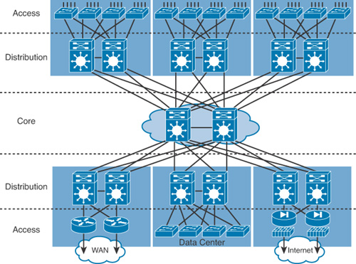
Table 31-1 summarizes the reasons STP places a port in forwarding or blocking state.
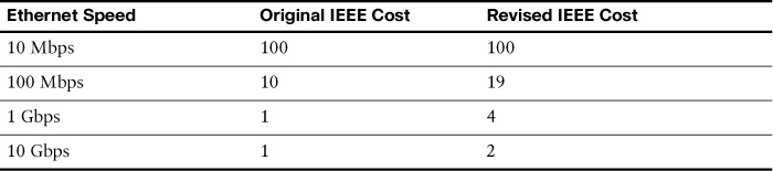
Port bandwidth is used to determine the cost to reach the root bridge. Table 31-2 lists the default port costs defined by IEEE, which had to be revised with the advent of 10-Gbps ports.
STP uses the four states shown in Figure 31-3 as a port transitions from blocking to forwarding.

A fifth state, disabled, occurs either when a network administrator manually disables the port or a security violation disables the port.
STP Varieties
Several varieties of STP have emerged after the original IEEE 802.1D:
![]() STP: The original specification of STP, defined in 802.1D, provides a loop-free topology in a network with redundant links. STP is sometimes referred to as Common Spanning Tree (CST) because it assumes one spanning tree instance for the entire bridged network, regardless of the number of VLANs.
STP: The original specification of STP, defined in 802.1D, provides a loop-free topology in a network with redundant links. STP is sometimes referred to as Common Spanning Tree (CST) because it assumes one spanning tree instance for the entire bridged network, regardless of the number of VLANs.
![]() PVST+: Per-VLAN Spanning Tree Plus is a Cisco enhancement of STP that provides a separate 802.1D spanning tree instance for each VLAN configured in the network.
PVST+: Per-VLAN Spanning Tree Plus is a Cisco enhancement of STP that provides a separate 802.1D spanning tree instance for each VLAN configured in the network.
![]() RSTP: Rapid STP, or IEEE 802.1w, is an evolution of STP that provides faster convergence than STP. However, RSTP still only provides for a single instance of STP.
RSTP: Rapid STP, or IEEE 802.1w, is an evolution of STP that provides faster convergence than STP. However, RSTP still only provides for a single instance of STP.
![]() Rapid PVST+: Cisco enhancement of RSTP that uses PVST+. Rapid PVST+ provides a separate instance of 802.1w per VLAN.
Rapid PVST+: Cisco enhancement of RSTP that uses PVST+. Rapid PVST+ provides a separate instance of 802.1w per VLAN.
![]() Multiple Spanning Tree Protocol: MSTP is an IEEE standard inspired by the earlier Cisco proprietary Multiple Instance STP (MISTP) implementation. MSTP maps multiple VLANs into the same spanning tree instance. The Cisco implementation of MSTP is MST, which provides up to 16 instances of RSTP and combines many VLANs with the same physical and logical topology into a common RSTP instance.
Multiple Spanning Tree Protocol: MSTP is an IEEE standard inspired by the earlier Cisco proprietary Multiple Instance STP (MISTP) implementation. MSTP maps multiple VLANs into the same spanning tree instance. The Cisco implementation of MSTP is MST, which provides up to 16 instances of RSTP and combines many VLANs with the same physical and logical topology into a common RSTP instance.
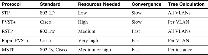
Part of your switch administration skill set is the ability to decide which type of STP to implement. Table 31-3 summarizes the features of each STP flavor.
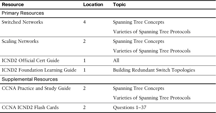
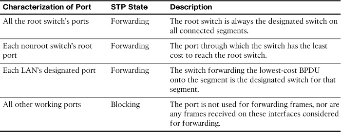
Study Resources
For today’s exam topics, refer to the following resources for more study.