Day 7. Serial Connections
CCNA 200-101 ICND2 Exam Topics
![]() Configure and verify operational status of a serial interface
Configure and verify operational status of a serial interface
![]() Configure and verify a basic WAN serial connection
Configure and verify a basic WAN serial connection
Key Topics
Today and tomorrow, you review one of the most common types of WAN connections, especially in long-distance communications: a point-to-point connection (also called a serial or leased-line connection).
Serial Communications
As shown in Figure 7-1, point-to-point connections are used to connect LANs to service provider WANs and to connect LAN segments within an enterprise network.

Communication across a serial connection is a method of data transmission in which the bits are transmitted sequentially over a single channel. This method is in contrast to parallel communications in which bits can be transmitted simultaneously over multiple wires, as shown in Figure 7-2.

There are many different serial communication standards, each one using a different signaling method. Three important serial communication standards affect LAN-to-WAN connections:
![]() RS-232: Most serial ports on personal computers conform to the RS-232C or newer RS-422 and RS-423 standards. Both 9-pin and 25-pin connectors are used. A serial port is a general-purpose interface that can be used for almost any type of device, including modems, mice, and printers. These types of peripheral devices for computers have been replaced by new and faster standards such as USB, but many network devices use RJ-45 connectors that conform to the original RS-232 standard.
RS-232: Most serial ports on personal computers conform to the RS-232C or newer RS-422 and RS-423 standards. Both 9-pin and 25-pin connectors are used. A serial port is a general-purpose interface that can be used for almost any type of device, including modems, mice, and printers. These types of peripheral devices for computers have been replaced by new and faster standards such as USB, but many network devices use RJ-45 connectors that conform to the original RS-232 standard.
![]() V.35: Typically used for modem-to-multiplexer communication, this ITU standard for high-speed synchronous data exchange combines the bandwidth of several telephone circuits. In the United States, V.35 is the interface standard used by most routers and DSUs that connect to T1 carriers. V.35 cables are high-speed serial assemblies designed to support higher data rates and connectivity between DTEs and DCEs over digital lines. There is more on DTEs and DCEs later in this section.
V.35: Typically used for modem-to-multiplexer communication, this ITU standard for high-speed synchronous data exchange combines the bandwidth of several telephone circuits. In the United States, V.35 is the interface standard used by most routers and DSUs that connect to T1 carriers. V.35 cables are high-speed serial assemblies designed to support higher data rates and connectivity between DTEs and DCEs over digital lines. There is more on DTEs and DCEs later in this section.
![]() HSSI: A High-Speed Serial Interface (HSSI) supports transmission rates up to 52 Mbps. Engineers use HSSI to connect routers on LANs with WANs over high-speed lines, such as T3 lines. Engineers also use HSSI to provide high-speed connectivity between LANs, using Token Ring or Ethernet. HSSI is a DTE/DCE interface developed by Cisco Systems and T3 plus Networking to address the need for high-speed communication over WAN links.
HSSI: A High-Speed Serial Interface (HSSI) supports transmission rates up to 52 Mbps. Engineers use HSSI to connect routers on LANs with WANs over high-speed lines, such as T3 lines. Engineers also use HSSI to provide high-speed connectivity between LANs, using Token Ring or Ethernet. HSSI is a DTE/DCE interface developed by Cisco Systems and T3 plus Networking to address the need for high-speed communication over WAN links.
HDLC
High-Level Data Link Control (HDLC) uses synchronous serial transmission to provide error-free communication between two points. HDLC defines a Layer 2 framing structure that allows for flow control and error control through the use of acknowledgments. Each frame has the same format, whether it is a data frame or a control frame. HDLC is the default setting on Cisco synchronous serial interfaces.
HDLC Encapsulation
Although Cisco HDLC (also called cHDLC) is proprietary, Cisco has allowed many other network equipment vendors to implement it. Cisco HDLC frames contain a field for identifying the network protocol being encapsulated. Figure 7-3 compares standard HDLC to Cisco HDLC.
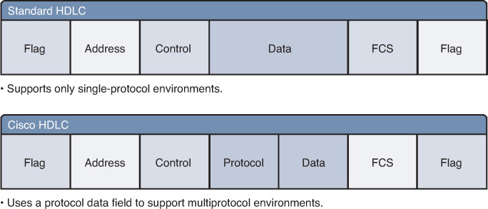
The following descriptions summarize the fields illustrated in the figure:
![]() Flag: The frame always starts and ends with an 8-bit flag with the pattern 01111110. When frames are transmitted consecutively, the end flag of the first frame is used as the start flag of the next frame.
Flag: The frame always starts and ends with an 8-bit flag with the pattern 01111110. When frames are transmitted consecutively, the end flag of the first frame is used as the start flag of the next frame.
![]() Address: In point-to-point HDLC connections, this field is empty.
Address: In point-to-point HDLC connections, this field is empty.
![]() Control: The Control field uses three formats, depending on the type of HDLC frame used:
Control: The Control field uses three formats, depending on the type of HDLC frame used:
![]() Information (I) frame: I-frames carry upper-layer information and some control information.
Information (I) frame: I-frames carry upper-layer information and some control information.
![]() Supervisory (S) frame: S-frames provide control information and are sequenced.
Supervisory (S) frame: S-frames provide control information and are sequenced.
![]() Unnumbered (U) frame: U-frames support control purposes and are not sequenced.
Unnumbered (U) frame: U-frames support control purposes and are not sequenced.
![]() Protocol (used only in Cisco HDLC): This field specifies the protocol type encapsulated within the frame (such as 0x0800 for IP).
Protocol (used only in Cisco HDLC): This field specifies the protocol type encapsulated within the frame (such as 0x0800 for IP).
![]() Data: A variable-length field that contains Layer 3 packets.
Data: A variable-length field that contains Layer 3 packets.
![]() Frame check sequence (FCS): Usually a cyclic redundancy check (CRC) used by the receiver to check for errors.
Frame check sequence (FCS): Usually a cyclic redundancy check (CRC) used by the receiver to check for errors.
Configuring HDLC
By default, you use Cisco HDLC as a Point-to-Point Protocol on leased lines between two Cisco devices. If you are connecting to a non-Cisco device that does not support Cisco HDLC, use synchronous PPP.
If the default encapsulation method has been changed, use the encapsulation hdlc command to reenable HDLC, as shown in the following configuration:
R1(config)# interface serial 0/0/0
R1(config-router)# encapsulation hdlc
Verifying HDLC
When configured or at the default setting, “Encapsulation HDLC” should be reflected in the command output of the show interfaces command, as shown in Example 7-1.
Example 7-1 Verifying HDLC with the show interfaces Command
R1# show interfaces serial 0/0/0
Serial0/0/0 is up, line protocol is up (connected)
Hardware is HD64570
Description: Link to R2
Internet address is 10.1.1.1/30
MTU 1500 bytes, BW 1544 Kbit, DLY 20000 usec, rely 255/255, load 1/255
Encapsulation HDLC, loopback not set, keepalive set (10 sec)
Last input never, output never, output hang never
Last clearing of "show interface" counters never
<output omitted>