
CHAPTER 10
Accessing Subobjects and Using Modeling Helpers
Understanding the modeling types
Using normals
Working with subobjects
Using Soft Selection
Using helper objects and utilities
Modeling is the process of pure creation. Whether it is sculpting, building with blocks, construction work, carving, architecture, or advanced injection molding, many different ways exist for creating objects. Max includes many different model types and even more ways to work with them.
This chapter introduces the various modeling methods in Max. It also explains the common modeling components, including normals and subobjects. The chapter also covers many utilities and helpers that, well, help as you begin to model objects. The purpose of this chapter is to whet your whistle for modeling and to cover some of the general concepts that apply to all models. More specific details on the various modeling types are presented in the subsequent chapters, so onward into the realm of creation.
Exploring the Model Types
You can climb a mountain in many ways, and you can model one in many ways. You can make a mountain model out of primitive objects like blocks, cubes, and spheres, or you can create one as a polygon mesh. As your experience grows, you'll discover that some objects are easier to model using one method, and some are easier using another. Max offers several different modeling types to handle various modeling situations.
Parametric objects versus editable objects
All geometric objects in Max can be divided into two general categories—parametric objects and editable objects. Parametric means that the geometry of the object is controlled by variables called parameters. Modifying these parameters modifies the geometry of the object. This powerful concept gives parametric objects lots of flexibility. For example, the sphere object has a parameter called Radius. Changing this parameter changes the size of the sphere. Parametric objects in Max include all the objects found in the Create menu.
Editable objects do not have this flexibility of parameters, but they deal with subobjects and editing functions. The editable objects include Editable Spline, Mesh, Poly, Patch, and NURBS (Non-Uniform Rational B-Splines). Editable objects are listed in the Modifier Stack with the word Editable in front of their base object (except for NURBS objects, which are simply called NURBS Surfaces). For example, an editable mesh object is listed as Editable Mesh in the Modifier Stack.
Note
Actually, NURBS objects are a different beast altogether. When created using the Create menu, they are parametric objects, but after you select the Modify panel, they are editable objects with a host of subobject modes and editing functions.
Editable objects aren't created; instead, they are converted or modified from another object. When a primitive object is converted to a different object type like an Editable Mesh or a NURBS object, it loses its parametric nature and can no longer be changed by altering its base parameters. Editable objects do have their advantages, though. You can edit subobjects such as vertices, edges, and faces of meshes—all things that you cannot edit for a parametric object. Each editable object type has a host of functions that are specific to its type. These functions are discussed in the coming chapters.
Note
Several modifiers enable you to edit subobjects while maintaining the parametric nature of an object. These include Edit Patch, Edit Mesh, Edit Poly, and Edit Spline.
Max includes the following model types:
- Primitives: Basic parametric objects such as cubes, spheres, and pyramids. The primitives are divided into two groups consisting of Standard and Extended Primitives. The AEC Objects are also considered primitive objects. A complete list of primitives is covered in Chapter 5, “Creating and Editing Primitive Objects.”
- Shapes and splines: Simple vector shapes such as circles, stars, arcs, and text, and splines such as the Helix. These objects are fully renderable. The Create menu includes many parametric shapes and splines. These parametric objects can be converted to Editable Spline objects for more editing. These are covered in Chapter 12, “Drawing and Editing 2D Splines and Shapes.”
- Meshes: Complex models created from many polygon faces that are smoothed together when the object is rendered. These objects are available only as Editable Mesh objects. Meshes are covered in Chapter 13, “Modeling with Polygons.”
- Polys: Objects composed of polygon faces, similar to mesh objects, but with unique features. These objects also are available only as Editable Poly objects. Poly objects are covered in Chapter 13, “Modeling with Polygons.” The Graphite Modeling Tools are designed to work on Editable Poly objects. These tools are covered in Chapter 14, “Using the Graphite Modeling Tools and Painting with Objects.”
- Patches: Based on spline curves; patches can be modified using control points. The Create menu includes two parametric Patch objects, but most objects can also be converted to Editable Patch objects. Bonus Chapter 5 on the CD, “Working with NURBS,” covers patches in detail.
- NURBS: Stands for Non-Uniform Rational B-Splines. NURBS are similar to patches in that they also have control points. These control points define how a surface spreads over curves. NURBS are covered in Bonus Chapter 5 on the CD, “Working with NURBS.”
- Compound objects: A miscellaneous group of model types, including Booleans, loft objects, and scatter objects. Other compound objects are good at modeling one specialized type of object such as Terrain or BlobMesh objects. All the Compound objects are covered in Chapter 27, “Working with Compound Objects.”
- Body objects: Solid objects that are imported from an SAT file produced by a solid modeling application like Revit have the concept of volume. Max mesh objects typically only deal with surfaces but can be converted to a Body object. All the information on Body objects is covered in Chapter 28, “Working with Solids and Body Objects.”
- Particle systems: Systems of small objects that work together as a single group. They are useful for creating effects such as rain, snow, and sparks. Particles are covered along with the Particle Flow interface in Chapter 41, “Creating Particles and Particle Flow.”
- Hair and fur: Modeling hundreds of thousands of cylinder objects to create believable hair would quickly bog down any system, so hair is modeled using a separate system that represents each hair as a spline. The Hair and Fur modifiers are covered in Chapter 29, “Adding and Styling Hair and Fur, and Using Cloth.”
- Cloth systems: Cloth—with its waving, free-flowing nature—behaves like water in some cases and like a solid in others. Max includes a specialized set of modifiers for handling cloth systems. Creating and using a cloth system is discussed in Chapter 29, “Adding and Styling Hair and Fur, and Using Cloth.”
Note
Hair, fur, and cloth are often considered effects or dynamic simulations instead of modeling constructs, so their inclusion on this list should be considered a stretch.
With all these options, modeling in Max can be intimidating, but you learn how to use each of these types the more you work with Max. For starters, begin with primitive or imported objects and then branch out by converting to editable objects. A single Max scene can include multiple object types.
Converting to editable objects
Of all the commands found in the Create menu and in the Create panel, you won't find any menus or subcategories for creating editable objects.
To create an editable object, you need to import it or convert it from another object type. You can convert objects by right-clicking on the object in the viewport and selecting the Convert To submenu from the pop-up quadmenu, or by right-clicking on the base object in the Modifier Stack and selecting the object type to convert to in the pop-up menu.
Once converted, all the editing features of the selected type are available in the Modify panel, but the object is no longer parametric and loses access to its common parameters such as Radius and Segments. However, Max also includes specialized modifiers such as the Edit Poly modifier that maintain the parametric nature of primitive objects while giving you access to the editing features of the Editable object. More on these modifiers is presented in the later modeling chapters.
Caution
If a modifier has been applied to an object, the Convert To menu option in the Modifier Stack pop-up menu is not available until you use the Collapse All command.
The pop-up menu includes options to convert to editable mesh, editable poly, editable patch, and NURBS. If a shape or spline object is selected, then the object can also be converted to an editable spline. Using any of the Convert To menu options collapses the Modifier Stack.
Objects can be converted between the different types several times, but each conversion may subdivide the object. Therefore, multiple conversions are not recommended.
Converting between object types is done automatically using Max's best guess, but if you apply one of the Conversion modifiers to an object, several parameters are displayed that let you define how the object is converted. For example, the Turn to Mesh modifier includes an option to Use Invisible Edges, which divides polygons using invisible edges. If this option is disabled, then the entire object is triangulated. The Turn to Patch modifier includes an option to make quads into quad patches. If this option is disabled, all quads are triangulated.
The Turn to Poly modifier includes options to Keep Polygons Convex, Limit Polygon Size, Require Planar Polygons, and Remove Mid-Edge Vertices. The Keep Polygons Convex option divides any polygon that is concave, if enabled. The Limit Polygon Size option lets you specify the maximum allowable polygon size. This can be used to eliminate any pentagons and hexagons from the mesh. The Require Planar Polygons option keeps adjacent polygons as triangles if the angle between them is greater than the specified Threshold value. The Remove Mid-Edge Vertices option removes any vertices caused by intersections with invisible edges.
All Conversion modifiers also include options to preserve the current subobject selection (including any soft selection) and to specify the Selection Level. The From Pipeline option uses the current subobject selection that is selected on the given object. After a Conversion modifier is applied to an object, you must collapse the Modifier Stack in order to complete the conversion.
Understanding Normals
Before moving on to the various subobjects, you need to understand what a normal is and how it is used to tell which way the surface is facing. Normals are vectors that extend outward perpendicular to the surface of an object. These vectors aren't rendered and are used only to tell which way the surface face is pointing. If the normal vector points toward the camera, then the polygon is visible, but if it points away from the camera, then you are looking at its backside, which is visible only if the Backface Cull option in the Object Properties dialog box is disabled.
Several other properties also use the normal vector to determine how the polygon face is shaded, smoothed, and lighted. Normals are also used in dynamic simulations to determine collisions between objects.
Viewing normals
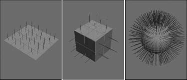
In all mesh subobject modes except for Edge, you can select the Show Normals option to see any object's normals and set a Scale value. Figure 10.1 shows a Plane, a Box, and a Sphere object. Each object has been converted to an Editable Mesh with all faces selected in Face subobject mode and with the Show Normals option selected.
Tutorial: Cleaning up imported meshes
Many 3D formats are mesh-based, and importing mesh objects sometimes can create problems. By collapsing an imported model to an Editable Mesh, you can take advantage of several of the editable mesh features to clean up these problems.
FIGURE 10.1 The Show Normals option shows the normal vectors for each face in a Plane, a Box, and a Sphere.
Cross-Reference
The Modifier menu includes two modifiers that you can use to work with normals. The Normals and Edit Normals modifiers are covered in Chapter 26, “Deforming Surfaces and Using the Mesh Modifiers.”
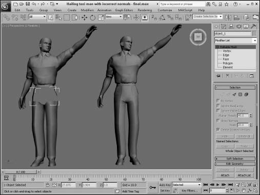
Figure 10.2 shows a model that was exported from Poser using the 3ds format. Notice that the model's waist is black. It appears this way because I've turned off the Backface Cull option in the Object Properties dialog box. If it were turned on, his waist would be invisible. The problem here is that the normals for this object are pointing in the wrong direction. This problem is common for imported meshes, and you'll fix it in this tutorial.
To fix the normals on an imported mesh model, follow these steps:
- Open the Hailing taxi man with incorrect normals.max file from the Chap 10 directory on the CD.
- Select the problem object—the waist on the right mesh. Open the object hierarchy by clicking the plus sign to the left of the Editable Mesh object in the Modifier Stack, and then select Element subobject mode and click on the waist area.
- In the Selection rollout, select the Show Normals option and set the Scale value to a small number such as 0.1.
The normals are now visible. Notice that some of them point outward, and some of them point inward.
- With the element subobject still selected, click the Unify button in the Surface Properties rollout and then click the Flip button until all normals are pointing outward.
This problem is fixed, and the waist object is now a visible part of the mesh. The fixed mesh on the right looks just like the original mesh on the left without the ugly black shorts, as shown in Figure 10.2.
FIGURE 10.2 This mesh suffers from objects with flipped normals, which makes them invisible.
Working with Subobjects
All the editable modeling types offer the ability to work with subobjects. Subobjects are the elements that make up the model and can include vertices, edges, faces, polygons, and elements. These individual subobjects can be selected and transformed just like normal objects using the transformation tools located on the main toolbar. But, before you can transform these subobjects, you need to select them. You can select subobjects only when you're in a particular subobject mode. Each editable object type has a different set of subobjects.
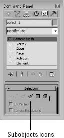
If you expand the object's hierarchy in the Modifier Stack (by clicking the small plus sign to the left of the object's name), all subobjects for an object are displayed, as shown in Figure 10.3. Selecting a subobject in the Modifier Stack places you in subobject mode for that subobject type. You can also enter subobject mode by clicking on the subobject icons located at the top of the Selection rollout or by pressing the 1 through 5 keys on the keyboard. When you're in subobject mode, the subobject title and the icon in the Selection rollout are highlighted yellow. You can work with the selected subobjects only while in subobject mode. To transform the entire object again, you need to exit subobject mode, which you can do by clicking either the subobject title or the subobject icon, or by pressing one of the keyboard shortcuts, 1–5.
Tip
You can also access the subobject modes using the right-click quadmenu. To exit a subobject mode, select Top Level in the quadmenu.
FIGURE 10.3 Expanding an editable object in the Modifier Stack reveals its subobjects.
Subobject selections can be locked with the Selection Lock Toggle (spacebar) and be made into a Selection Set by typing a name into the Named Selection Set drop-down list on the main toolbar. After a Selection Set is created, you can recall it any time you are in that same subobject mode. Named Selection Sets can then be copied and pasted between objects using the Copy and Paste buttons found in the Selection rollout for most editable objects.
Using Soft Selection
When working with editable mesh, poly, patches, or splines, the Soft Selection rollout, shown in Figure 10.4, becomes available in subobject mode. Soft Selection selects all the subobjects surrounding the current selection and applies transformations to them to a lesser extent. For example, if a face is selected and moved a distance of 2, then with linear Soft Selection, the neighboring faces within the soft selection range move a distance of 1. The overall effect is a smoother transition.
Note
The Soft Selection options are different for the various modeling types. For example, the Editable Mesh includes a standard set of options like those in Figure 10.4, but the Editable Poly object has more options, including a Paint Soft Selection mode.
The Use Soft Selection parameter enables or disables the Soft Selection feature. The Edge Distance option sets the range (the number of edges from the current selection) that the Soft Selection will affect. If disabled, the distance is determined by the Falloff amount. The Affect Backfacing option applies the Soft Selection to selected subobjects on the backside of an object. For example, if you are selecting vertices on the front of a sphere object and the Affect Backfacing option is enabled, then vertices on the opposite side of the sphere are also selected.
FIGURE 10.4 The Soft Selection rollout is available only in subobject mode.
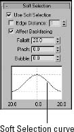
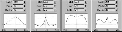
The Soft Selection curve shows a graphical representation of how the Soft Selection is applied. The Falloff value defines the spherical region where the Soft Selection has an effect. The Pinch button sharpens the point at the top of the curve. The Bubble button has an opposite effect and widens the curve. Figure 10.5 shows several sample values and the resulting curve.
The Customize User Interface dialog box recognizes a mode to Edit Soft Selection if you select one of the modeling types in the Group drop-down list, which you can assign to a keyboard shortcut. You can toggle this mode on and off for the Edit Mesh modifier using the keyboard shortcut 7, but for Edit Poly, you'll need to set it yourself.
Cross-Reference
The Customize User Interface and assigning keyboard shortcuts are covered in Chapter 4, “Changing Interface Units and Setting Preferences.”
Once the Edit Soft Selection mode is enabled, the cursor changes to a custom cursor. When this cursor appears, you can drag to change the Soft Selection's falloff value. If you click, the cursor changes and lets you drag to change the Pinch value. One more click and you can edit the Bubble value and another click returns you to the falloff edit mode. Pressing the keyboard shortcut again exits Edit Soft Selection mode.
For Editable Poly objects, the bottom of the Soft Selection rollout includes a Paint Soft Selection section. You can use these controls to paint the soft selection weights that subobjects receive.
Cross-Reference
For more information on the paint interface and these controls, see Chapter 26, “Deforming Surfaces and Using the Mesh Modifiers.”
FIGURE 10.5 The Soft Selection curve is affected by the Falloff, Pinch, and Bubble values.
Tutorial: Soft selecting a heart shape from a plane
Soft Selection enables a smooth transition between subobjects, but sometimes you want the abrupt edge. This tutorial looks at moving some subobject vertices in a plane object with and without Soft Selection enabled.
To move subobject vertices with and without Soft Selection, follow these steps:
- Open the Soft selection heart.max file from the Chap 10 directory on the CD.
This file contains two simple plane objects that have been converted to Editable Mesh objects. Several vertices in the shape of a heart are selected.
- The vertices on the first plane object are already selected; in Vertex subobject mode, click the Select and Move button (or press the W key), move the cursor over the selected vertices, and drag upward in the Left viewport away from the plane.
- Exit subobject mode, select the second plane object, and enter Vertex subobject mode. The same vertices are again selected. Open the Soft Selection rollout, enable the Use Soft Selection option, and set the Falloff value to 40.
- Click the Select and Move button (or press the W key), and move the selected vertices upward. Notice the difference that Soft Selection makes.
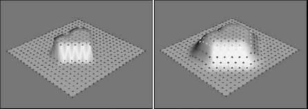
Figure 10.6 shows the two resulting plane objects with the heart selections.
FIGURE 10.6 Soft Selection makes a smooth transition between the subobjects that are moved and those that are not.
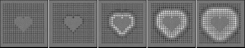
When you select subobjects, they turn red. Non-selected subobjects are blue, and soft selected subobjects are a gradient from orange to yellow, depending on their distance from the selected subobjects. This visual clue provides valuable feedback on how the Soft Selection affects the subobjects. Figure 10.7 shows the selected vertices from the preceding tutorial with Falloff values of 0, 20, 40, 60, and 80.
FIGURE 10.7 A gradient of colors shows the transition zone for soft selected subobjects.
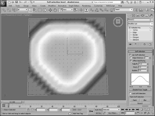
For the Editable Poly and Editable Patch objects, the Soft Selection rollout includes a Shaded Face Toggle button below its curve. This button shades the surface using the soft selection gradient colors, as shown in Figure 10.8. This shaded surface is displayed in any shaded viewports. The cooler colors have less of an impact over the transform.
FIGURE 10.8 The Shaded Face Toggle shades the surface using the soft selection gradient colors.
Applying modifiers to subobject selections
The preceding chapter introduced modifiers and showed how they can be applied to entire objects. But you can also apply modifiers to subobjects. If the modifier isn't available for subobjects, it is excluded from the Modifier List or disabled in the Modifiers menu.
If your object isn't an editable object with available subobjects, you can still apply a modifier using one of the specialized Select modifiers. These modifiers let you select a subobject and apply a modifier to it without having to convert it to a non-parametric object. These Select modifiers include Mesh Select, Poly Select, Patch Select, Spline Select, Volume Select, FFD (Free Form Deformers) Select, and Select by Channel. You can find all these modifiers in the Modifiers ![]() Selection submenu.
Selection submenu.
After you apply a Select modifier to an object, you can select subobjects in the normal manner using the hierarchy in the Modifier Stack or the subobject icons in the Parameters rollout. Any modifiers that you apply after the Select modifier (they appear above the Select modifier in the Modifier Stack) affect only the subobject selection.
Using Modeling Helpers
In the Create panel (and the Create menu) is a category of miscellaneous objects called helpers (the icon looks like a tape measure). These objects are useful in positioning objects and measuring dimensions. The buttons in the Helper category include Dummy, Container, Crowd, Delegate, ExposeTM, Grid, Point, Tape, Protractor, and Compass.
Cross-Reference
The Container helper is covered in Chapter 9, “Grouping, Linking, and Parenting Objects.” Crowd and Delegate helpers are discussed in Chapter 39, “Animating Characters with CAT,” and the Expose Transform helper object is covered in Chapter 35, “Using Animation Layers, Modifiers and Complex Controllers.”
Using Dummy and Point objects
The Dummy object is a useful object for controlling complex object hierarchies. A Dummy object appears in the viewports as a simple cube with a pivot point at its center, but the object will not be rendered and has no parameters. It is used only as an object about which to transform objects. For example, you could create a Dummy object that the camera could follow through an animation sequence. Dummy objects are used in many examples throughout the remainder of the book.
The Point object is very similar to the Dummy object in that it also is not rendered and has minimal parameters. A Point object defines a point in space and is identified as an X, an Axis Tripod, or a simple Box. The Center Marker option places an X at the center of the Point object (so X really does mark the spot). The Axis Tripod option displays the X-, Y-, and Z-axes, the Cross option extends the length of the marker along each axis, and the Box option displays the Point object as a Box. The Size value determines how big the Point object is.
Tip
The Size parameter actually makes Point helpers preferable over Dummy helpers because you can parametrically change their size.
The Constant Screen Size option keeps the size of the Point object constant, regardless of how much you zoom in or out of the scene. The Draw on Top option draws the Point object above all other scene objects, making it easy to locate. The main purpose for the Point object is to mark positions within the scene.
Caution
Point objects are difficult to see and easy to lose. If you use a point object, be sure to name it so you can find it easily in the Select from Scene dialog box.
Measuring coordinate distances
The Helpers category also includes several handy utilities for measuring dimensions and directions. These are the Tape, Protractor, and Compass objects. The units are all based on the current selected system units.
Using the Measure Distance tool
In the Tools menu is a command to Measure Distance. This tool is easy to use. Just select it and click at the starting point and again at the ending point; the distance between the two clicks is shown in the Status Bar at the bottom of the interface. Measure Distance also reports the Delta values in the X, Y, and Z directions. You can use this tool with the Snap feature enabled for accurate measurements.
Using the Tape helper
You use the Tape object to measure distances. To use it, simply drag the distance that you would like to measure and view the resulting dimension in the Parameters rollout. You can also set the length of the Tape object using the Specify Length option. You can move and reposition the end points of the Tape object with the Select and Move button, but the Rotate and Scale buttons have no effect.
Using the Protractor helper
The Protractor object works in a manner similar to the Tape object, but it measures the angle between two objects. To use the Protractor object, click in a viewport to position the Protractor object. (The Protractor object looks like two pyramids aligned point to point and represents the origin of the angle.) Then click the Pick Object 1 button, and select an object in the scene. A line is drawn from the Protractor object to the selected object. Next, click the Pick Object 2 button. The angle-formed objects and the Protractor object are displayed in the Parameters rollout. The value changes when either of the selected objects or the Protractor is moved.
Note
All measurement values are presented in gray fields within the Parameters rollout. This gray field indicates that the value cannot be modified.
Using the Compass helper
The Compass object identifies North, East, West, and South positions on a planar star-shaped object. You can drag the Compass object to increase its size.
The Grid helper object is discussed along with grids in Chapter 7, “Transforming Objects, Pivoting, Aligning, and Snapping.” The Compass object is mainly used in conjunction with the Sunlight System, which you can learn about in Chapter 20, “Using Lights and Basic Lighting Techniques.”
Using the Measure utility
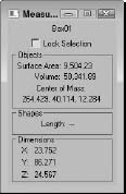
In the Utilities panel is another useful tool for getting the scoop on the current selected object: the Measure utility. You can open the Measure utility as a floater dialog box, shown in Figure 10.9. This dialog box displays the object's name along with its Surface Area, Volume, Center of Mass, Length (for shapes), and Dimensions. It also includes an option to lock the current selection.
FIGURE 10.9 The Measure utility dialog box displays some useful information.
Using the Level of Detail utility
As a scene is animated, some objects are close to the camera, and others are far from it. Rendering a complex object that is far from the camera doesn't make much sense. Using the Level of Detail (LOD) utility, you can have Max render a simpler version of a model when it is farther from the camera and a more complex version when it is close to the camera.
Cross-Reference
The MultiRes modifier can also create real-time level of detail updates. It is covered in Chapter 26, “Deforming Surfaces and Using the Mesh Modifiers.”
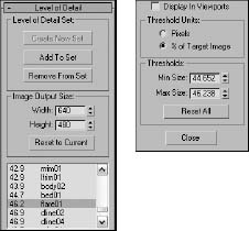
To open the utility, click the More button in the Utility panel and select the Level of Detail utility. A single rollout is loaded into the Utility panel, as shown in Figure 10.10. To use this utility, you need to create several versions of an object and group them together. The Create New Set button lets you pick an object group from the viewports. The objects within the group are individually listed in the rollout pane.
If you select a listed object, you can specify the Threshold Units in pixels or as a percentage of the target image. For each listed item, you can specify minimum and maximum thresholds. The Image Output Size values are used to specify the size of the output image, and the different models used are based on the size of the object in the final image. The Display in Viewports check box causes the appropriate LOD model to appear in the viewport.
FIGURE 10.10 The Level of Detail utility (split into two parts) can specify how objects are viewed, based on given thresholds.
Summary
Understanding the basics of modeling helps you as you build scenes. In this chapter, you've seen several different object types that are available in Max. Many of these types have similar features such as Soft Selection. Several helper objects can assist as well. This chapter covered the following topics:
- Understanding parametric objects and the various modeling types
- Viewing normals
- Using subobjects and soft selections
- Using helper objects and utilities
In the next chapter, you learn another excellent tool for deforming mesh objects. Modifiers allow specific types of deformation to be applied to an object such as bending, twisting, or rippling a surface.