Chapter 4
Clicker 2 for STM32 development board
Abstract
There are many ARM-based development boards (or kits) in the market place. Clicker 2 for STM32 is one of the popular development boards used in high-end complex projects. This chapter describes the basic hardware details of the Clicker 2 for STM32 hardware. The board contains LEDs, switches, digital and analog input-output ports, power-supply, two microbus compatible sockets, external interrupt lines, UART pins, I2C ports, SPI ports, and the on-board oscillator. Additionally, the programming details of the on-board STM32F407 microcontroller is described using the preloaded Bootloader program, an external ST-LINK V2 hardware programming device, or the mikroProg for STM32 programming device.
Keywords
Clicker 2 for STM32
microcontroller development board
mikroBUS
mikroBUS socket
on-board LED
on-board switch
ST-LINK V2
mikroProg
oscillator
Bootloader
4.1. Overview
In the last chapter we had a look at some of the popular ARM processor development boards. In this chapter we shall be looking in detail the features of the Clicker 2 for STM32 development board which is used in all the projects in this book.
4.2. Clicker 2 for STM32 hardware
The Clicker 2 for STM32 is a very powerful microcontroller development board using the STM32F407VGT6 32-bit ARM Cortex-M4-based microcontroller operating at up to 168 MHz. The board is called Clicker 2 since it has two mikroBUS sockets mounted on it. The board incorporates 1 MB of flash memory and over 192 KB of SRAM memory. The board (see Fig. 4.1) is developed and manufactured by mikroElektronika (www.mikroe.com), and it has the following basic features:
- • STM32F407VGT6 microcontroller (100 pins)
- • 168 MHz operation speed
- • 1 MB flash memory
- • over 192 KB SRAM
- • 25 MHz and 32.768 kHz external crystals
- • 52 programmable GPIO pins
- • 16-bit and 32-bit timers
- • 3 × 12-bit analog-to-digital converters
- • SPI, I2C, UART, USART, RTC, Ethernet interfaces
- • 2 mikroBUS sockets to accept Click boards
- • USB mini connector
- • 2 LEDs
- • 2 push-button switches
- • 2 × 26 connection pads
- • power manager IC
- • reset button
- • external battery connector

Figure 4.1 Clicker 2 for STM32 development board.
The Clicker 2 for STM32 board has 2 × 26 header type connectors at both ends. The board can therefore be plugged-in on a suitable size breadboard so that the input-output pins can easily be accessed during project development. This is the recommended method to use the board for project development.
4.2.1. On-board LEDs
There are two on-board LEDs, LD1 and LD2, connected to port pins PE12 and PE15, respectively. The cathodes of the LEDs are connected to ground via 2.2K current limiting resistors and their anodes are connected directly to the corresponding port pins. Thus, the LEDs are turned ON when logic 1 is applied to the corresponding output ports of the microcontroller.
4.2.2. On-board push-button switches
There are two on-board push-button switches, T2 and T3, connected to port pins PE0 and PA10, respectively. The switches are connected to port pins and are normally pulled HIGH through 10K resistors. Pushing a switch forces its output to logic 0 so that the corresponding port pins read logic 0.
Fig. 4.2 shows the LED and push-button connections on the board.

Figure 4.2 LED and push-button connections.
4.2.3. Reset switch
A reset switch is provided on the board. Pressing this switch resets the microcontroller, forcing it to enter into the Bootloader mode for about 5 s. If there is no connection request from a corresponding Bootloader program on a PC then the processor initializes its registers into default reset state and then starts to execute the user program.
4.2.4. Power supply
The board can be powered either from a PC or from an external suitable 5V DC supply through its mini USB port (see Fig. 4.3), or using an external 3.7V Li-polymer battery (see Fig. 4.4). Battery charging current and charging voltage are 300 mA and 4.2 V, respectively. In normal operations, the board is connected to a PC through a mini USB cable where this interface is used to provide power to the board and at the same time to program the microcontroller on the board.
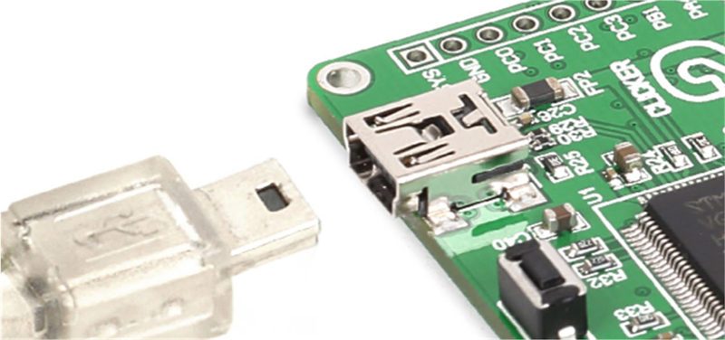
Figure 4.3 Powering from the mini USB port.
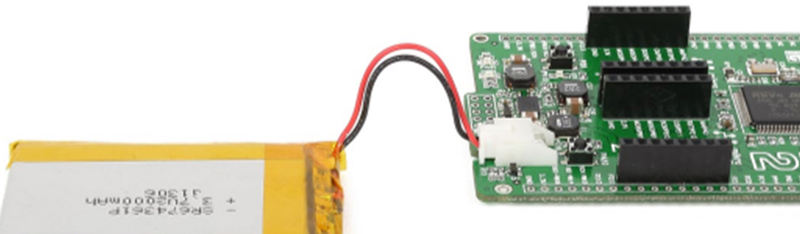
Figure 4.4 Powering using an external Li-polymer battery.
4.2.5. On-board mikroBUS sockets
There are two mikroBUS sockets on-board (labeled mikroBUS 1 and mikroBUS 2) for connecting any type of Click board to the processor. Click boards are manufactured by mikroElektronika (www.mikroe.com) and there are over 800 Click boards available (at the time of writing this book, since the number is increasing all the time) that can be plugged-in to the mikroBUS compatible sockets. mikroBUS interface provides connectivity for the commonly used protocols such as SPI, I2C, UART, analog input, etc. Click boards simplify the task of overall system development. There are Click boards for various analog and digital sensors, displays, relays, communication boards, and so on. Some example Click boards are:
- • temperature and humidity sensor
- • accelerometer
- • gyrator
- • pressure sensor
- • gas sensor
- • GPS
- • Wi-Fi
- • Ethernet
- • ZigBee
- • CAN bus
- • 7-segment LED
- • Mini LCD
- • OLED
- • buzzer
- • bar graph LED
- • EEPROM
- • line follower
- • RF transmitter/receiver
- • heart rate sensor
- • ADC and DAC
- • DC motor controller
- • stepper motor controller
- • and many more
mikroBUS sockets have 16 pins, organized as 2 × 8 pins in a dual-in-line type socket. Pin 1 is located at the top left-hand side of the socket. Fig. 4.5 shows the pin configuration of the two mikroBUS sockets on the Clicker 2 for the STM32 development board.
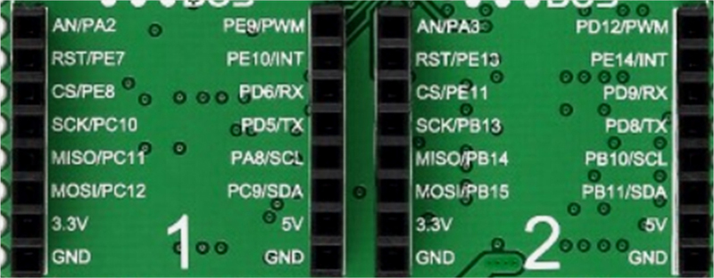
Figure 4.5 mikroBUS pin configurations.
4.2.6. Input-output pins
Fig. 4.6 shows the Clicker 2 for STM32 development board input-output pin names as viewed from the back of the board. The input-output pins can be categorized as follows:

Figure 4.6 Input-output pins.
Digital input-output
PB5,PB6,PB7,PC7,PC8,PC13,PD7,PD10,PD11,PD13,PD14,PD15,PE1,PE2,PE3,PE4,PE6,
Analog inputs
PC0.PC1,PC2,PC3,PB1,PA4,PC4
Interrupt lines
PD0,PD1,PD2,PD3
UART lines
PA0 (TX), PA1(RX)
I2C lines
PB10 (SCL), PB11(SDA)
SPI lines
PB13 (SCK), PB14 (SDI), PB15 (SDO)
Power and ground
+3.3V and +5V power and ground lines are provided on the mikroBUS sockets. Additionally, the mainboard provides +3.3V power and ground lines.
In addition, the board is equipped with the following:
- • reset push-button (RST)
- • on-off slide switch
- • GND and +3.3V power pins
- • power management and battery charger module
- • JTAG programming interface
- • mini USB socket
4.2.7. Oscillators
In addition to the internal 16 MHz RC oscillator, the board is equipped with a 25 MHz and a 32,768 Hz crystal-based oscillators for accurate processor timing and accurate RTC applications (see Fig. 4.7).

Figure 4.7 On-board 25 MHz and 32,768 Hz crystals.
4.2.8. Programming the on-board microcontroller
The microcontroller on the development board can be programmed using one of the following methods:
- • A Bootloader program is preloaded in the program memory of the on-board microcontroller. By downloading the compatible mikroBootloader program to our PC, we can program the on-board microcontroller. This method is described in detail in the next chapter.
- • Using an external ST-LINK V2 programmer device (Fig. 4.8).
- • Using the mikroProg for STM32 programmer device (Fig. 4.9).
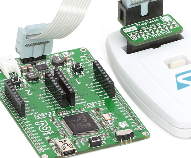
Figure 4.8 ST-LINK V2 programmer.

Figure 4.9 mikroProg for STM32 programmer.
The Bootloader programming method is used in all the projects in this book as it does not require any additional external programming devices, and it is also the cheapest and the fastest way of programming the on-board microcontroller.
4.3. Summary
In this chapter we had a look at the basic features of the Clicker 2 for the STM32 development board. Since this board is used in all the projects in the book, it is important that the reader has an understanding of its basic features.
In the next chapter we shall be looking at the various ARM microcontroller programming tools including the mikroC Pro for ARM compiler and the IDE used in all the projects in this book.
..................Content has been hidden....................
You can't read the all page of ebook, please click here login for view all page.