In multitasking systems, it is very common for the tasks to cooperate and share the available resources of the target microcontroller. For example, various tasks may want to share the communications interfaces that can only be used by one task at a time. Semaphores and mutexes are used to synchronize the access to shared resources in a system. In this chapter, the FreeRTOS semaphore and mutex application program interface functions are described in detail. Several real-time and multitasking tested projects are given in this chapter with the complete program listings and full documentation in order to demonstrate how to create binary and counting semaphores and mutexes, how to give and take semaphores and mutexes, and how to use the semaphores and mutexes with queues.
Keywords
giving semaphores
taking semaphores
task synchronization
mutexes
resource sharing
FreeRTOS
exclusive access
11.1. Overview
In multitasking systems, it is very common for the tasks to cooperate and share the available resources. For example, various tasks may want to share the communications interfaces that can only be used by one task at a time. The readers may think that the resources can be shared using simple techniques (e.g., flags) as shown in the following example:
while (serial port is busy); //Wait until serial port is free
Serial port busy flag = 1; // Set busy flag
Send data to serial port; // Send data
Serial port busy flag = 0; // Clear busy flag
At first glance, it may look like that exclusive access is given to the serial port and that there are no problems. However, in a multitasking system, it is highly possible that another task jumps at the point between the first and the second lines and grabs the serial port before the first task is finished. The serial port can be thought of being in a critical section that needs to be protected so that only one task has access to it at any time.
Resource sharing such as above is handled in FreeRTOS using mutexes and semaphores.
Mutex: A mutex is also called a binary semaphore. Mutexes are used to protect critical sections of a code so that only one task has access to it at any time. The operation of a mutex is such that a mutex must be created before it can be used. A task then takes a mutex before entering a critical section. During this time, no other tasks can have access to the shared resource since the mutex controlling the critical section is not available. When the task finishes its processing within the critical section, it gives the mutex. At this point, the mutex is available for any other tasks who may want to use the critical section. A task that takes a mutex must always give it back; otherwise, no other task can access the critical region.
Semaphore: Semaphores can be binary or counting. A binary semaphore is similar to a mutex as it has two states. A counting semaphore contains a counter with an upper bound which is defined at the time the semaphore is created. The counter keeps track of limited access to the shared resource (i.e., critical section). When a task wants to use the critical section, it takes the semaphore and, as a result, the counter is decremented if it is not zero. Another task can also take the semaphore where the counter is decremented again. When the count value reaches zero, the resource is not available and furtherer attempts to take the semaphore will fail. When a task releases the semaphore (i.e., gives the semaphore), then the counter value is incremented. Semaphores that are created to manage resources should be created with an initial count value equal to the number of resource that are available.
Notice that although the mutexes and binary semaphores are very similar, there are some important differences between them. Mutexes include priority inheritance, binary semaphores do not. The priority of a task that holds a mutex is raised if another task of higher priority attempts to obtain the same mutex. The task that already holds the mutex is said to inherit the priority of the task attempting to take the same mutex. The inherited priority will be disinherited when the mutex is returned. A binary semaphore does not need to give back the semaphore after it has been taken. Creating a mutex or a semaphore returns a handle to the creator. This handle identifies the created mutex or the semaphore.
In this chapter, we are looking at the various FreeRTOS semaphore and mutex functions. An example project is given to show how a mutex can be used in a real-time multitasking project.
Further information on semaphores and mutexes can be obtained from the document at the following website:
The application program interface (API) function xSemaphoreCreateBinary() creates a binary semaphore and returns its handle. The format of this function call is:
xSemaphoreCreateBinary(void);
The function has no parameters, but it returns the following values:
Return values
NULL: The semaphore could not be created because there is insufficient heap memory available for FreeRTOS to allocate the semaphore data structures.
Any other value: The semaphore was created successfully. The returned value is a handle by which the created semaphore can be referenced.
Binary semaphores are recommended for implementing synchronization between tasks or between an interrupt and a task. Mutexes ate recommended for implementing simple mutual exclusion.
The API function xSemaphoreCreateMutex() creates a mutex and returns its handle. The format of this function is:
xSemaphoreCreateMutex(void);
This function has no parameters and returns the handle as in creating a binary semaphore.
Parameter configSUPPORT_DYNAMIC_ALLOCATION must be set to 1 in file FreeRTOS Config.h, or simply left undefined, for this function to be available.
11.3. Creating a counting semaphore
The API function xSemaphoreCreateCounting() creates a counting semaphore and returns its handle. The format of the function is:
xSemaphore: This is the handle of the semaphore being queried.
Return value
The count of the semaphore referenced by the handle passed in the xSemaphore parameter.
11.5. Giving and taking the semaphores
The API function call xSemaphireGive() gives (or releases) a semaphore that has been created using a call to vSemaphoreCreateBinary(), xSemaphoreCreateCounting(), or xSemaphoreCreateMutex() and has also been successfully “taken.” The format of the function is:
xSemaphoreGive(SemaphoreHandle_t xSemaphore);
Parameter
xSemaphore: The semaphore being “given.” A semaphore is referenced by a variable of type SemaphoreHandle_t and must be explicitly created before being used.
Return values
pdPASS: The semaphore “give” operation was successful.
pdFAIL: The semaphore “give” operation was not successful because the task calling xSemaphoreGive() is not the semaphore holder. A task must successfully “take” a semaphore before it can successfully “give” it back.
The API function call xSemaphoreTake() takes (or obtains) a semaphore that has previously been created using a call to vSemaphoreCreateBinary(), xSemaphoreCreateCounting(), or xSemaphoreCreateMutex(). The format of the function is:
xSemaphore: The semaphore being “taken.” A semaphore is referenced by a variable of type SemaphoreHandle_t and must be explicitly created before being used.
xTicksToWait: The maximum amount of time the task should remain in the Blocked state to wait for the semaphore to become available, if the semaphore is not available immediately. If xTicksToWait is zero, then xSemaphoreTake() will return immediately if the semaphore is not available. The block time is specified in tick periods, so the absolute time it represents is dependent on the tick frequency. The pdMS_TO_TICKS() macro can be used to convert a time specified in milliseconds to a time specified in ticks. Setting xTicksToWait to portMAX_DELAY will cause the task to wait indefinitely (without timing out), provided the parameter INCLUDE_vTaskSuspend is set to 1 in file FreeRTOSConfig.h.
Return values
pdPASS: Returned only if the call to xSemaphoreTake() was successful in obtaining the semaphore. If a block time was specified (xTicksToWait was not zero), then it is possible that the calling task was placed into the Blocked state to wait for the semaphore if it was not immediately available, but the semaphore became available before the block time expired.
pdFAIL: Returned if the call to xSemaphoreTake() did not successfully obtain the semaphore. If a block time was specified (xTicksToWait was not zero), then the calling task will have been placed into the Blocked state to wait for the semaphore to become available, but the block time expired before this happened.
11.6. Project 24: sending internal and external temperature data to a PC
Description: In this project, two analog temperature sensor chips are used: a temperature sensor to measure the temperature inside an oven and another temperature sensor to measure the ambient temperature outside the oven. There are three tasks in the project in addition to the Idle task. The external and internal temperatures are read by the two tasks, and these data are sent to another task that displays the data on the PC screen. External temperature is displayed every 5 seconds and the internal one every 2 seconds. The display task is assumed to be in a critical section where the sending tasks must take/give a mutex in order to share the UART and send data to the PC.
Aim: The aim of this project is to show how a mutex can be created and taken and given by tasks in a multitasking environment in order to access a shared critical region.
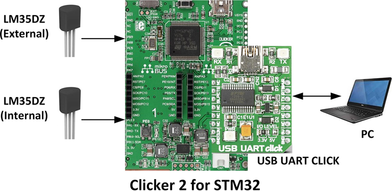
Block diagram: The block diagram of this project is shown in Fig. 11.1. The following components are used in this project in addition to the Clicker 2 for STM32 development board:
• USB UART Click board
• 2 × analog temperature sensor chips
Figure 11.1Block diagram of the project.
Circuit diagram:Fig. 11.2 shows the circuit diagram of the project. In this project, two LM35DZ analog temperature sensor chips are used. The sensor called External is connected to analog input PA2 of the Clicker 2 for STM32 development board. Another LM35DZ, called Internal, is connected to analog input PA4. Both sensors are powered from +5 V supply derived from the development board. The USB UART Click board is connected to mikroBUS Socket 2 of the development board. Connection to the PC is through a mini USB cable connected between the USB UART Click board and any USB port of a PC.
Figure 11.2Circuit diagram of the project.
Program listing: LM35DZ is a three-pin analog temperature sensor chip having the following specifications:
• 0°C to 100°C measurement range
• Operates from 4 to 20 V
• Less than 60 μA current
• ±4°C linearity
The output of the chip is an analog voltage directly proportional to the measured temperature. The relationship between the measured temperature and the output voltage is given by:
T = 10 mV/°C
For example, if the output voltage is 200 mV, then the measured temperature is 20°C; if the output voltage is 350 mV, the measured temperature is 35°C, and so on.
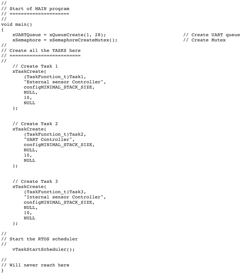
The program listing is shown in Fig. 11.3 (program: mutex.c). There are three tasks in the system, in addition to the Idle task. Inside the main program, a queue is created with the handle xUARTQueue, having a size of 1 with 28 bytes. Also, a mutex is created with the handle xSemaphore. Each task performs the following:
Figure 11.3mutex.c program listing.
Task 1
This is the External temperature task. The task reads the ambient analog temperature from LM35DZ, converts the reading into millivolts, and then converts it to °C by dividing with 10. In this task, analog input port PA2 of the Clicker 2 for STM32 development board is used. The reading is then converted into a string using the built-in function IntToStr(). The task then attempts to take the mutex. If the mutex is taken successfully (i.e., pdPASS is returned), then the temperature together with a heading is sent to the UART, as shown in the following code:
The task then gives the mutex and waits for 5 seconds.
Task 3
This task is similar to Task 1, but here the internal oven temperature is read and sent to UART. Analog port PA4 of the Clicker 2 for STM32 development board is used.
Task 2
This is the UART controller task. At the beginning of the task, the UART is initialized to operate at 9600 baud. The task then checks the queue and reads the message if there is 1. The message consists of two parts: a heading and the measured temperature. The message is sent to UART, which is displayed on the PC screen via a terminal emulation software.
Fig. 11.4 shows an output on the PC screen when the program is run.
Figure 11.4Output on the screen.
11.7. Summary
In this chapter, we have learned the concepts of semaphores and mutexes. A project is given using the FreeRTOS to show how a mutex can be created and a critical region can be shared by two tasks by taking and giving the mutex.
In the next chapter, we shall be looking at the concept of Event Groups in multitasking systems and give examples of using them in multitasking projects.