Critical sections (also known as critical regions) are regions of code that are surrounded by two macros where entry to these sections of code is controlled so that the code is entered by only one task at any time. A critical section is entered by calling taskENTER_CRITICAL() and exited by calling taskEXIT_CRITICAL(). These calls do not have any parameters and also do not return any values. Critical sections can also be implemented using mutexes and semaphores, but it is quicker to use the entry and exit macros described in this chapter. Interrupts are disabled inside the critical sections, either globally, or up to a specific priority level. A real-time multitasking FreeRTOS based project is given in this chapter to illustrate how a critical section can be used in a project. This chapter also explains how the scheduler can be suspended.
Keywords
FreeRTOS
Clicker 2 for STM32
mikroC Pro for ARM
critical section
critical region
entering and exiting critical sections
sharing the UART
suspending the scheduler
temperature measurement
17.1. Overview
In the previous chapter, we have developed several projects using the topic of Task Notifications. In this chapter, we are looking at another important topic, the Critical Sections.
Critical sections (also known as critical regions) are regions of code that are surrounded by two macros where entry to these sections of code is controlled so that the code is entered by only one task at any time. A critical section is entered by calling taskENTER_CRITICAL() and exited by calling taskEXIT_CRITICAL(). These calls do not have any parameters and also do not return any values. Critical sections can also be implemented using mutexes and semaphores, but it is quicker to use the entry and exit macros described in this chapters. Interrupts are disabled inside the critical sections, either globally, or up to a specific priority level. Interrupts whose priorities are above the value assigned to parameter configMAX_SYSCALL_INTERRUPT_PRIORITY are enabled and those interrupts whose priorities are at or below configMAX_SYSCALL_INTERRUPT_PRIORITY are disabled. It is also important that the critical sections must not be called from inside an interrupt service routine. More will be discussed in a later chapter on FreeRTOS and interrupt service routines.
Preemptive context switching cannot occur inside a critical section since interrupts are disabled inside these sections. As a result of this, when a task enters a critical section, it is guaranteed that it will run until it exits from the region. A task should not go into a Blocked state inside a critical section, or it should not yield to ask the scheduler to perform context switching.
The code inside a critical section must be short as long code may affect the scheduling of tasks in the program. Critical sections can be nested if required and it is safe to nest them. It is, however, important that all entries must be exited before a critical section is left by a task.
An example project is given in the next section to show how a critical section can be used in an application.
17.2. Project 42: critical sections – Sharing the UART
Description: This is a simple project. In this project, a task measures the outdoor temperature. Similarly, another task measures the indoor temperature. Both tasks share a UART and send their readings to the UART so that the measured values are displayed on a PC.
Aim: The aim of this project is to show how a critical section can be used in a project that shares the UART.
Block diagram: In this project, both the indoor temperature and the outdoor temperature are measured using the LM35DZ type analog temperature sensor chips as shown in Fig. 17.1.
Figure 17.1Block diagram of the project.
Circuit diagram: The LM35DZ is a three-pin analog temperature sensor chip that was used in an earlier project, and therefore, its specifications are not repeated here again.
The following connections were made in this project between the Clicker 2 for STM32 development board and external components:
Development board pin
External component pin
PA2 (analog input)
LM35 output pin (for indoor temperature)
PA4
LM35 output pin (for outdoor temperature)
+5 V
LM35DZ Vcc pins
GND
LM35DZ GND pin
mikroBUS 2 socket
USB UART Click board
A USB UART Click board is plugged in to mikroBUS 2 socket of the development board. A mini USB cable is then connected between the USB UART Click board and the USB port of the PC. A terminal emulation software was used on the PC as described in earlier projects using the PC interface. Fig. 17.2 shows the circuit diagram of the project.
Figure 17.2Circuit diagram of the project.
Program listing: As described in earlier projects, LM35DZ gives an output voltage directly proportional to the measured temperature. That is,
T=Vo10
where T is the measured temperature in ˚C, and Vo is the sensor output voltage in millivolts. For example, at 20°C, the output voltage is 200 mV, at 30°C, the output voltage is 300 mV and so on. The following PDL shows the operation of the program:
TASK1
DO FOREVER
Read indoor temperature from LM35DZ
Convert to Degrees Centigrade
Call Display to display the data
Wait 1 second
ENDDO
TASK 2
DO FOREVER
Read outside temperature from LM35DZ
Convert to Degrees Centigrade
Call Display to display the data
Wait 1 second
ENDDO
Function display
Critical Section entry
Receive data from UART
Display data on PC screen
Critical Section exit
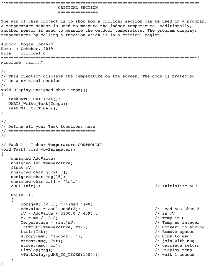
The program listing is shown in Fig. 17.3 (program: critical.c). The program consists of two tasks in addition to the Idle task. Task 1 reads the indoor temperature from the LM35DZ sensor chip. Task 2 reads the outdoor temperature using another LM35DZ sensor chip. Both tasks call a function named Display, which is protected by a critical section to display their readings on the PC screen.
Figure 17.3critical.c program listing.
The details of each task are given below:
TASK 1
Inside the main task loop, built-in function ADC1_Read(2) is called to read analog data from port PA2. The read value is then converted into Degrees Centigrade, converted into a string, leading spaces are removed and then function Display is called to display the temperature on the PC screen. The loop is repeated every second.
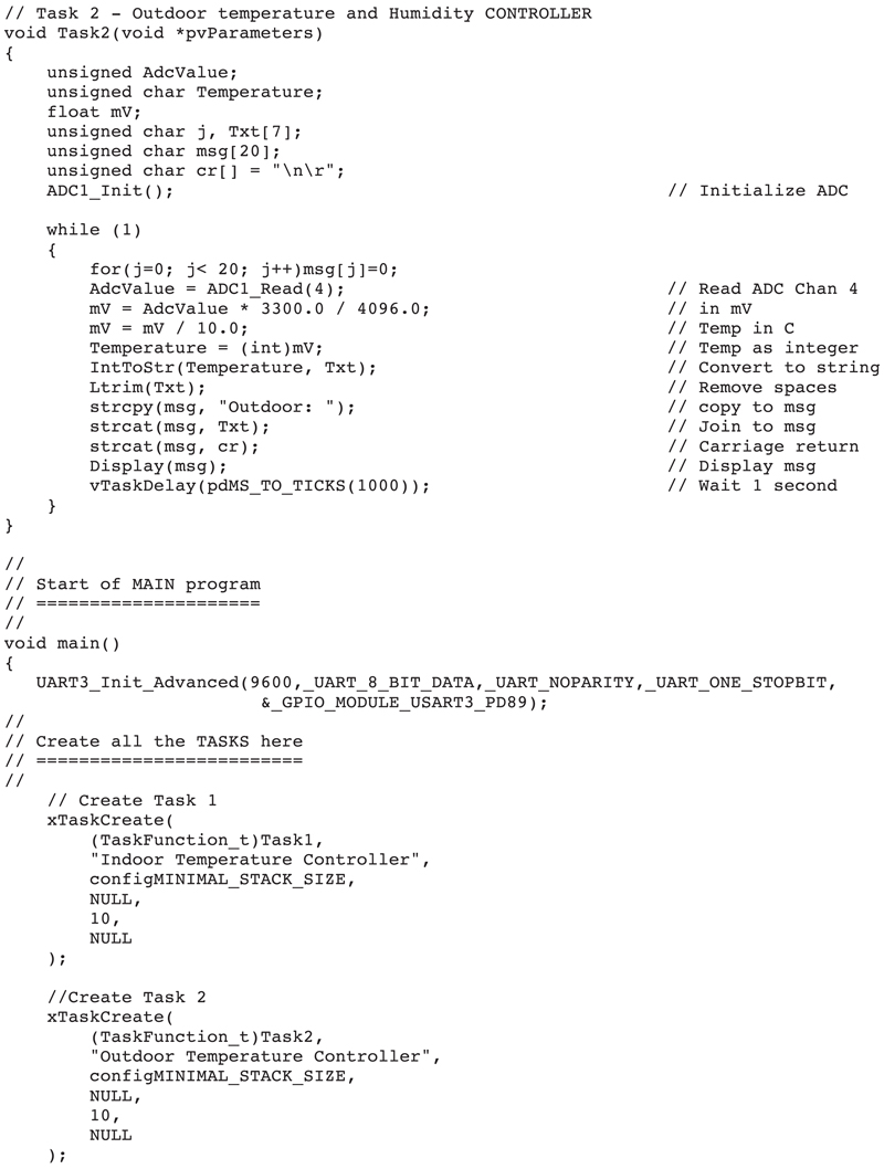
TASK 2
This task is similar to Task 1, but here function ADC1_Read(4) is called to read analog data from port PA4. The remainder code in this task is same as in Task 1.
Function display
This task calls UART to display the indoor and outdoor temperatures on the PC screen. The UART is enclosed inside a critical section by calling taskENTER_CRITICAL() and taskEXIT_CRITICAL().
Fig. 17.4 shows the indoor and outdoor temperatures displayed on the PC screen.
Figure 17.4Displaying the temperatures.
17.3. Suspending the scheduler
Another method of creating a critical section is to suspend the scheduler temporarily. Again, it is very important that the code inside the critical section is short and not time-consuming. The critical section created by suspending the scheduler is protected and can only be accessed from only one task at any time. Notice that interrupts remain enabled when the scheduler is suspended, but they will not lead to a task switch (i.e., kernel swapping). If an interrupt requests a context switch while the scheduler is suspended, then the request is held pending and is performed when the scheduler is resumed. It is important that API functions that may cause task switching (e.g., task delay, queues, tasks that may block the task) must not be used inside the critical section.
A critical section is created by suspending the scheduler using the API call vTaskSuspendALL() at the entry and xTaskResumeAll() at the exit of the critical section:
vTaskSuspendAll();
{
/* Critical section is here */
}
xTaskResumeAll();
It is possible to have nested suspending of the scheduler. The scheduler will return to normal operation when the nesting depth returns to zero.
17.4. Project 43: suspending the scheduler
Description: Project 42 can be modified so that the critical section is protected by suspending the scheduler before calling the UART function. The scheduler is resumed after the UART function. The only modification required to Project 42 is to modify function Display as follows:
void Display(unsigned char Temps[])
{
vTaskSuspendAll();
UART3_Write_Text(Temps);
xTaskResumeAll();
}
17.5. Summary
In this chapter, we have learned about the critical sections and also about the FreeRTOS API functions used to suspend and resume the scheduler.
In the next chapter, we shall be looking at the basic theory of Cortex-M4-based external and internal (timer) interrupts and learn how to use them in projects.