
Chapter 14
Some example projects
Abstract
This chapter is about developing basic level real-time multitasking projects using the FreeRTOS application program interface (API) functions. This chapter gives projects on the following topics using the Clicker 2 for STM32, microcontroller development board with the mikroC Pro for ARM Integrated Development Environment: square wave generation, frequency sweep waveform generation, RGB (Red-Green-Blue) light controller, USB UART Click board, software timer, home alarm system, magnetic reed-switch, keypad interface, ultrasonic sensors, ultrasonic car parking system, buzzer interface, stepper motors, bipolar stepper motor, unipolar stepper motor, full-mode control, half-mode control, motor rotation time, motor speed and RPM (revolutions per minute), Arduino, Arduino interface, communicating with an Arduino microcontroller development system, and analog temperature control.
Keywords
FreeRTOS
Clicker 2 for STM32
mikroC Pro for ARM
square wave generation
RGB light controller
home alarm system
ultrasonic car parking system
stepper motor
half-step mode
full-step mode
Arduino interface
14.1. Overview
In this chapter, various example projects are given at different levels of complexity to make the readers familiar on how to develop microcontroller-based projects using the FreeRTOS application program interface (API) functions. The projects aim to use most of the functions that we have covered up to this point in the book.
14.2. Project 31: square wave generation with adjustable frequency
Description: In this project, a square waveform is generated as in Project 29, but here the period of the waveform can be changed from the keyboard while the program is running in a multitasking environment. The user enters the required ON time of the waveform in milliseconds as an integer value. The lowest value that can be entered is 1 ms. It is assumed that the waveform has 50% duty cycle. That is, it has equal ON and OFF times. The total period of the waveform is, therefore, 2 * ON time.
Aim: The aim of this project is to show how a FreeRTOS software can be used to generate square waveform signal where the frequency can be entered from the keyboard. An auto-reload timer is created where its frequency can be changed without stopping the program.
Circuit diagram: The circuit diagram of the project is shown in Fig. 14.1. This is similar to Fig. 13.6, but here the USB UART Click board is used to interface the development board to a PC.
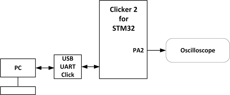
Figure 14.1 Circuit diagram of the project.
Program listing: The program listing (squarekey.c) is shown in Fig. 14.2. The program consists of two tasks in addition to the Idle task. Task 1 creates the square waveform, while Task 2 sets the required period. The operation of the program is as follows:


Figure 14.2 squarekey.c program listing.
Task 1
Create a timer with period of 2 ms
Start the timer
DO FOREVER
IF data are available in the queue THEN
Get the data from the queue
Change the period of the waveform
ELSE
Initiate task change (taskYIELD)
ENDIF
ENDDO
Task 2
Initialize UART at 9600 baud
DO FOREVER
Read the required period from the keyboard
Send the period to the queue
Calculate the frequency
Display the frequency on the screen
ENDDO
Task 1 creates the timer with a period of 2 ms initially by calling the API function:
xTimer = xTimerCreate(“SquareWave”, pdMS_TO_TICKS(1), pdTRUE, 0,
vSquareWaveForm);
The timer is then started with the function call:
xTimerStart(xTimer, 0);
The remainder of Task 1 runs in a loop and checks whether or not a message is available in the queue. If a message is available, then it is read and used to change the period of the waveform by the function call:
- xTimerChangePeriod(xTimer, pdMS_TO_TICKS(NewPeriod), 100);
If there is no message in the queue, then function taskYIELD() is called to give up the CPU so that the keyboard can grab the CPU.
Task 2 prompts the user to enter the required ON time of the waveform. This is then sent to the queue so that the period of the waveform can be changed as required. This task then calculates the resulting frequency of the waveform and displays it on the screen.
Fig. 14.3 shows the screen when the required ON time of the waveform was 2 ms. The resulting was captured using an oscilloscope and is shown in Fig. 14.4.

Figure 14.3 Setting the ON time to 2 ms.

Figure 14.4 Waveform on the oscilloscope.
14.3. Project 32: frequency sweep waveform generator
Description: In this project, a square waveform is generated as in the previous project, but here the frequency of the generated waveform is changed from a given starting value to an end value with the steps specified by the user. For example, the user may require the frequency to change from 100 to 500 Hz in steps of 50 Hz where the waveform at each frequency should be output for 5 seconds. As in the previous project, it is assumed that the waveform will have equal ON and OFF times. Sweep frequency waveform generators are commonly used in radio frequency applications.
Aim: The aim of this project is to show how a FreeRTOS software can be used to generate square waveform signal where the frequency can be changed in required steps entered from the keyboard. Auto-reload timer is created where its frequency can be changed without stopping the program.
Circuit diagram: The circuit diagram of the project is as in Fig. 14.1.
Program listing: The program listing (sweepfreq.c) is shown in Fig. 14.5. The program consists of two tasks in addition to the Idle task. Task 1 creates a timer with the default period of 1 ms and then stats the timer. This task then enters a loop. Inside the loop, the program reads the new user settings from the queue and then implements them. A structure is used to store the user settings, such as the starting frequency, ending frequency, and the step frequency:


Figure 14.5 sweepfreq.c program listing.
typedef struct Message
{
unsigned int StartFrequency;
unsigned int EndFrequency;
unsigned int StepFrequency;
} AMessage;
The starting and the ending frequencies are converted into milliseconds and stored in variables FirstValue and EndValue, respectively. Inside the program loop, the frequency is incremented by the step value and the period of the generated waveform is set accordingly. When the period of the generated waveform reaches the required end period, then the process repeats again where the generated waveform is set to have the starting frequency and so on. The frequency of the generated waveform is changed every 5 seconds.
Task 2 calls function Read_From_Keyboard() to read the starting frequency, ending frequency, and the step frequency after prompting the user to enter the required data:
- UART3_Write_Text(“ Enter Starting Frequency (Hz): ”);
- msg.StartFrequency = Read_From_Keyboard();
- UART3_Write_Text(“ Enter Ending Frequency (Hz): ”);
- msg.EndFrequency = Read_From_Keyboard();
- UART_Write_Text(“ Enter Frequency Step (Hz): ”);
- msg.StepFrequency = Read_From_Keyboard();
The user entered settings are then sent to a queue so that they can be received by Task 1:
- xQueueSend(xUARTQueue, &msg, pdMS_TO_TICKS(10));
An example run of the program is shown in Fig. 14.6. When an oscilloscope is connected to port pin AP2, the frequency of the generated square waveform will be changed from 100 to 500 Hz in steps of 100 Hz every 5 seconds.

Figure 14.6 Example run of the program.
14.4. Project 33: RGB light controller
Description: In this project, an RGB (red + green + blue) LED is connected to one of the ports of the development board. The program flashes the three LEDs independently and randomly so that a nice visual effect is created.
Aim: The aim of this project is to show how an RGB LED can be controlled from FreeRTOS using a different task for each LED color.
Circuit diagram: In this project, the KY-016 type RGB LED module is used. As shown in Fig. 14.7, this module has four pins, one pin for each LED, and a common GND pin. 150 Ohm current-limiting resistors are provided on the module to limit the current; therefore, there is no need to use external resistors. Sending a logic 1 (+3.3 V or +5 V) to an LED pin turns ON that LED. By turning the LEDs ON and OFF randomly, we can have a nice visual effect.

Figure 14.7 KY-016 RGB LED.
The circuit diagram of the project is shown in Fig. 14.8. The connections between the Clicker 2 for STM32 development board and the RGB LED are as follows (some of the mikroBUS 2 socket pins are used):
| RGB pin | Development board pin |
|---|---|
| Red (R) | PD12 |
| Green (G) | PE14 |
| Blue (B) | PD9 |
| – | GND |
Program listing: The program listing (rgb.c) is shown in Fig. 14.9. The program consists of three tasks, called Red, Green, and Blue, in addition to the Idle task. The three tasks are similar to each other. At the beginning of each task, the LED port controlled by the task is configured as an output port. The remainder of the task codes execute forever in loops established by While statements. Independent random numbers are generated in each task between 101 and 600 ms, and these random numbers determine the flashing rates of each LED. All the three tasks run at the same priority. The net effect is that a nice visual effect is created on the RGB LED module. Built-in function rand() generates random numbers between 0 and 32767. These numbers are converted to be within the limits of 101 and 600 as illustrated below:
- When rand() generates 0, the result of rand() %500 + 101 is 101
- When rand() generates 499, the result of rand() %500 + 101 is 600
- When rand() generates 32767, the result of rand() %500 + 101 is 166
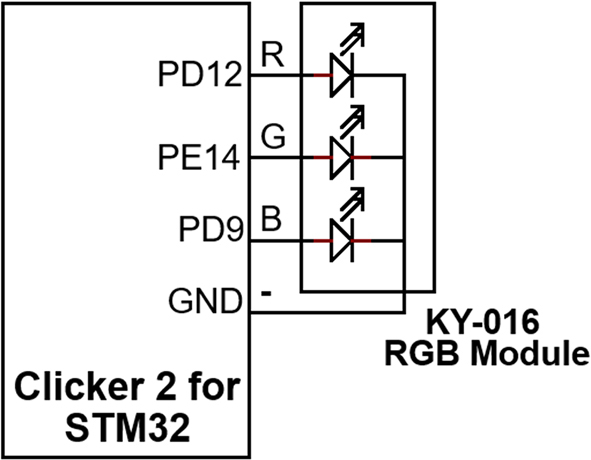
Figure 14.8 Circuit diagram of the project.
14.5. Project 34: home alarm system with keyboard
Description: This is a simple home alarm system, designed for a two-storey house with upstairs and downstairs. A keyboard is used to control the various operations of the designed alarm system. The details of the system are given later in this section with the help of a block diagram (Fig. 14.10).

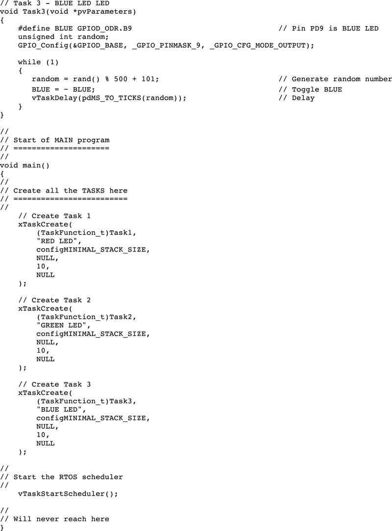
Figure 14.9 rgb.c program listing.
Aim: The aim of this project is to show how a simple home alarm system can be designed in a multitasking environment using FreeRTOS.
Block diagram: The block diagram of the system is shown in Fig. 14.10. There are four magnetic reed type sensors in the system (it is easy to expand the number of sensors in this system if desired). Two of the sensors are attached to two windows upstairs and are named as UpFwindow (Up Front window) and UpRwindow (Up Rear window). Two similar sensors are attached to the doors downstairs and are named as DownFdoor (Down Front door) and DownRdoor (Down Rear door). A buzzer is connected to the development board that is activated when the system is armed and one of the doors or windows is opened. The operation of the system is controlled from a PC keyboard for simplicity.
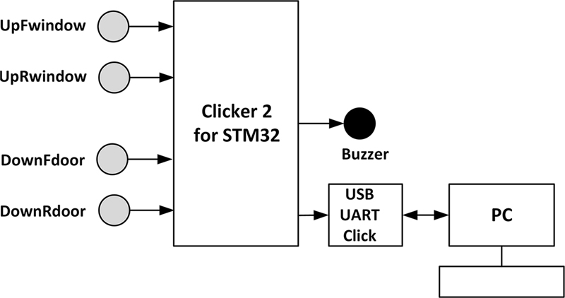
Figure 14.10 Block diagram of the system.
In this project, the KY-021 type mini reed switch module is used to detect when a window or a door is opened. This is a three-pin module with the connections GND, +V, and Signal. GND and +V pins are connected to the ground and power pins, respectively. The Signal pin can be connected to any general purpose input/output pin of the development board. An on-board 10 K resistor is connected between the +V and the S pins, as shown in Fig. 14.11. Reed switches are electrical switches operated by applied magnetic field. These switches consist of a pair of ferromagnetic flexible metal contacts in a sealed glass envelope (see Fig. 14.12). The contacts are normally open, closing when magnetic field (e.g., a magnet) is present near the contacts, and re-open, that is, return to their normal state when the magnetic field is removed. Reed switches are used in door and window mechanisms to detect when they are open or closed, and in many other security-based applications. In security applications, the reed switch and a magnet are mounted at either sides of an opening window or door as shown in Fig. 14.13. When the door or the window is closed, the magnet is close to the switch and the output state of the switch is at Logic 0. When the door or the window is opened, the magnet is separated from the switch and as a result the switch state goes to Logic 1.

Figure 14.11 KY-021 magnetic reed switch.

Figure 14.12 A typical magnetic reed switch.
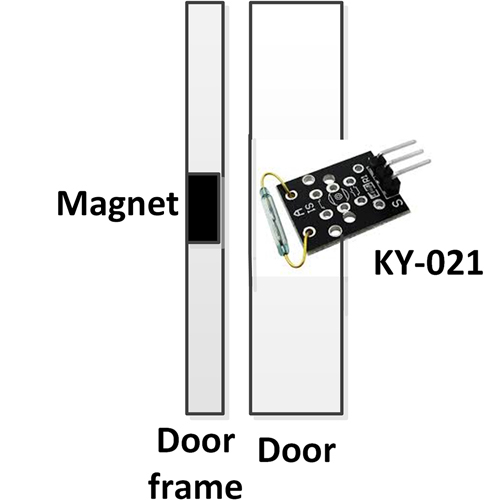
Figure 14.13 Reed switch and magnet.
A passive buzzer is used in this project so that when Logic 1 is sent to the buzzer, it generates sound at a fixed frequency. In a real alarm system, the buzzer may be replaced with a relay operated mains siren.
Operation of the system is through a keyboard. Valid keyboard commands are as follows:
Full: set the alarm to scan all four sensors
Part: set the alar to scan only the downstairs sensors (DownFdoor and DownRdoor)
Reset: clear alarm settings
Entering Full followed by the Enter key will arm all the sensors so that the system scans all four sensors to check if there is any possible entry to the house. Entering Part followed by the Enter key arms only the downstairs sensors so that it is safe to walk upstairs without activating the alarm. When the system is armed, the user is given 30 seconds to leave the house. Similarly, when a switch is activated (e.g., the front door opened), the system gives 30 seconds for it to be disarmed before setting the alarm. Entering Reset followed by the Enter key cancels the alarm setting, that is, disarms the system. This command is only activated if the correct password is entered at the keyboard. For demonstration purposes, the password in this project is set to FreeRTOS.
Circuit diagram: Fig. 14.14 shows the circuit diagram of the project. The following connections were made between the Clicker 2 for STM32 development board and the external world (these pins are located on the connector of the mikroBUS Socket 1 of the development board):
| Clicker 2 for STM32 pin | Connected to |
|---|---|
| PA2 | UpFwindow sensor |
| PE7 | UpRwindow sensor |
| PE8 | DownFdoor |
| PC10 | DownRdoor |
| PE9 | Buzzer |
| mikroBUS 2 | USB UART Click |
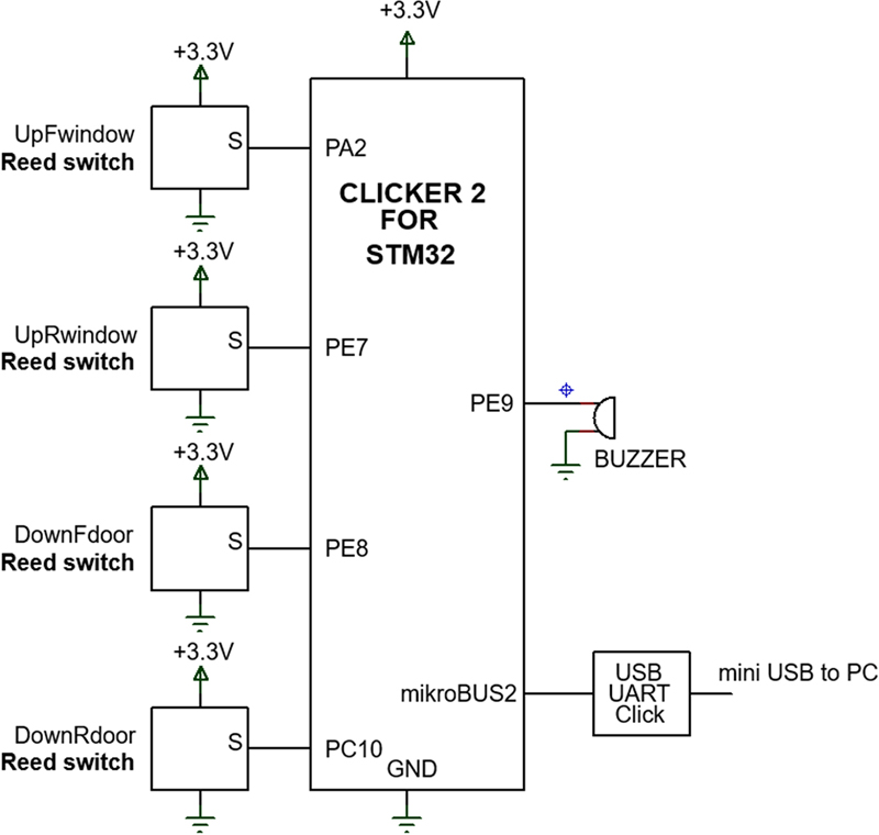
Figure 14.14 Circuit diagram of the project.
A USB UART Click board is connected to mikroBUS Socket 2 of the development board. This board is connected to a PC using a mini USB cable. Commands can be entered on the PC using a terminal emulation software as in the previous PC-based projects.
The operation of the program is shown in the PDL in Fig. 14.15.
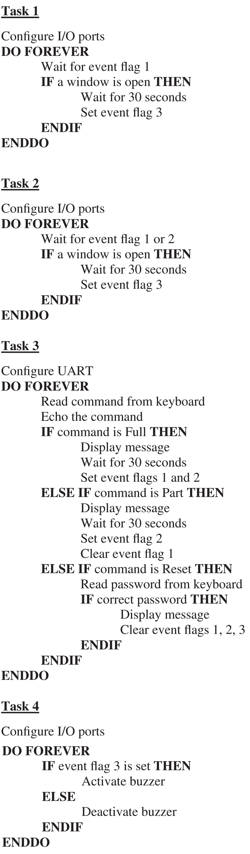
Figure 14.15 Operation of the program.
Program listing: The program listing (program: homealarm.c) is shown in Fig. 14.16. The program consists of four tasks in addition to the Idle task. Resource synchronization between the tasks is done using event flags. The following event flags are used in the program:
| Event flag 1 | When set (1), it means that both upstairs and downstairs are armed |
| When reset (0), it means that upstairs and downstairs are not armed | |
| Event flag 2 | When set (1), it means that downstairs only is armed. |
| When reset (0), it means that downstairs is not armed | |
| Event flag 3 | When set (1), it forces the buzzer to be ON |
| When reset (1), it forces the buzzer to be OFF |


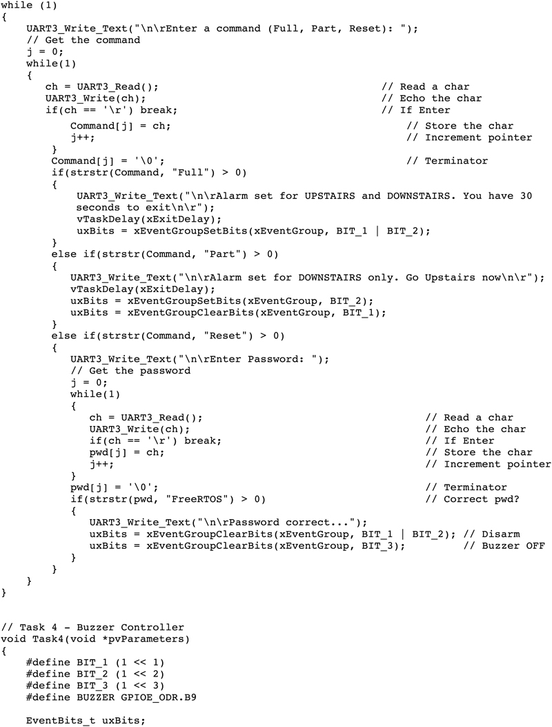


Figure 14.16 homealarm.c program listing.
Detailed operation of each task is summarized as follows:
Task 1
This is the upstairs controller task. At the beginning of this task, UpFwindow and UpRwindow are assigned to port pins PA2 and PE7, respectively, and these port pins are configured as outputs. The remainder of the task runs in an endless loop. Inside this loop the task waits until Event flag 1 is set. That is, until the system is armed. The task then checks the windows upstairs to make sure that they are closed. If a window is open, then either UpFwindow or UpRwindow sensor state will be OPEN. As a result of this, Event flag 3 will be set so that the alarm can be activated. Notice that 30 seconds of delay is inserted here as entry delay so that the user has enough time to enter the home and reset the system before the alarm activates.
Task 2
This is the downstairs controller task. Its operation is very similar to Task 1. Here, DownFdoor and DownRdoor reassigned to port pins PE8 and PC10, respectively, and these port pins are configured as outputs. This task waits for either Event flag 1 or 2 to be set before it checks the state of the door sensors. The remainder of the task operates as in Task 1, where the task checks whether the doors are closed or not and sets Event flag 3 to activate the buzzer if a door is open.
Task 3
This is the UART controller task. At the beginning of the task, UART is configured to operate at 9600 baud. The remainder of the task operates in an endless loop formed using a While statement. Inside this loop, the user is prompted to enter a command. Valid commands are Full, Part, and Reset. A command is received from the keyboard and is echoed back on the screen using the following code. The command is stored in character array Command and is terminated with a NULL character:
UART3_Write_Text(“
Enter a command (Full, Part, Reset): ”);
j = 0;
while(1)
{
ch = UART3_Read(); // Read a char
UART3_Write(ch); // Echo the char
if(ch==’
’) break; // If Enter
Command[j] = ch; // Store the char
j + +; // Increment pointer
}
Command[j] = ’�’;
As described earlier, commands Full and Part arm either the complete system or the downstairs only. The entered command is checked using the built-in function strstr(), which compares two strings and returns a NULL if the first string does not include the second string. If command Full is entered, a message is displayed and the task waits for 30 seconds as the exit delay so that the user can leave home without activating the alarm. After this delay, both Event flags 1 and 2 are set to arm the complete system. If command Part is entered, a message is displayed and the system again waits for 30 seconds as the exit delay and then sets Event flag 2, and at the same time clears Event flag 1. Command Reset is used to reset the system, that is, to disarm the system. This command should be entered when coming home so that the system can be disarmed. This command requires the user to enter the correct password before the system is reset. The password is hardcoded as FreeRTOS in this application. Event flags 1, 2, and 3 are cleared when the Reset command is entered so that the system is disarmed and at the same time the buzzer is deactivated.
Task 4
This is the buzzer controller task. This task waits for Event flag 3 to be set, and if it is set, it activates the buzzer, otherwise the buzzer is deactivated.
Fig. 14.17 shows the user commands entered on the keyboard.

Figure 14.17 User commands.
14.6. Project 35: ultrasonic car parking with buzzer
Description: In this project, an ultrasonic sensor is used to measure the distance to objects while parking a vehicle. The sensor is assumed to be mounted at the rear of the vehicle. A buzzer sounds to indicate the distance to any object behind the vehicle such that the activation rate of the buzzer increases as the vehicle gets closer to an object. The measured distance is displayed in centimeters on the PC screen for convenience.
Aim: The aim of this project is to show how an ultrasonic sensor can be used in a multitasking environment.
Block diagram: Fig. 14.18 shows the block diagram of the project.
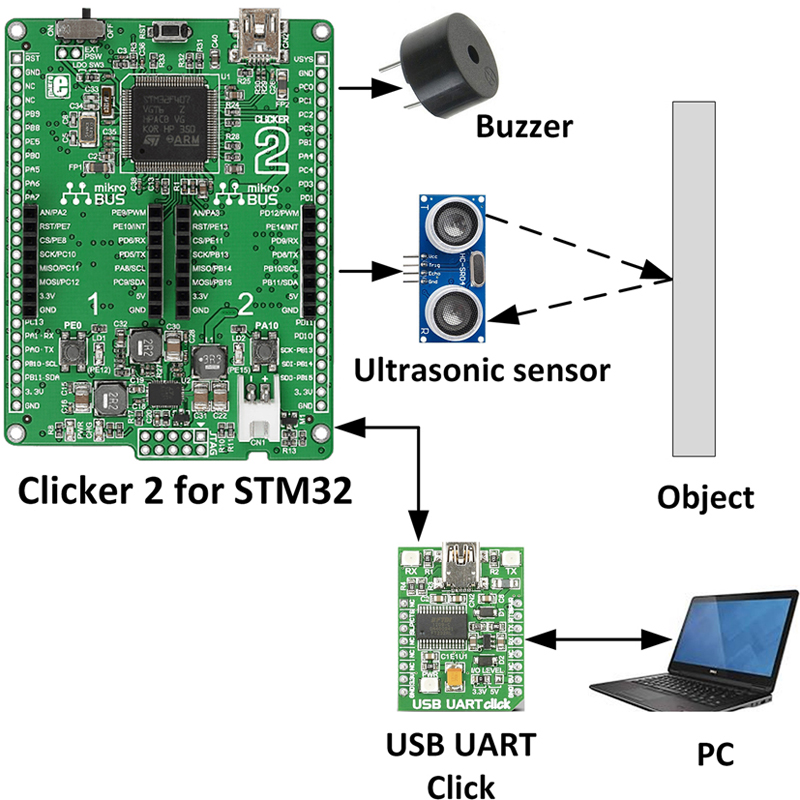
Figure 14.18 Block diagram of the project.
Circuit diagram: In this project, the HC-SR-04 type (Fig. 14.19) ultrasonic sensor pair is used. The output of this sensors is +5 V and, therefore, not compatible with the inputs of the Clicker 2 for STM32 development board. Resistive potential divider circuit is, therefore, used to lower the voltage to +3.3 V. The voltage at the output of the potential divider resistive circuit is:
- Vo = 5 V × 2 K / (2 K + 1 K) = 3.3 V
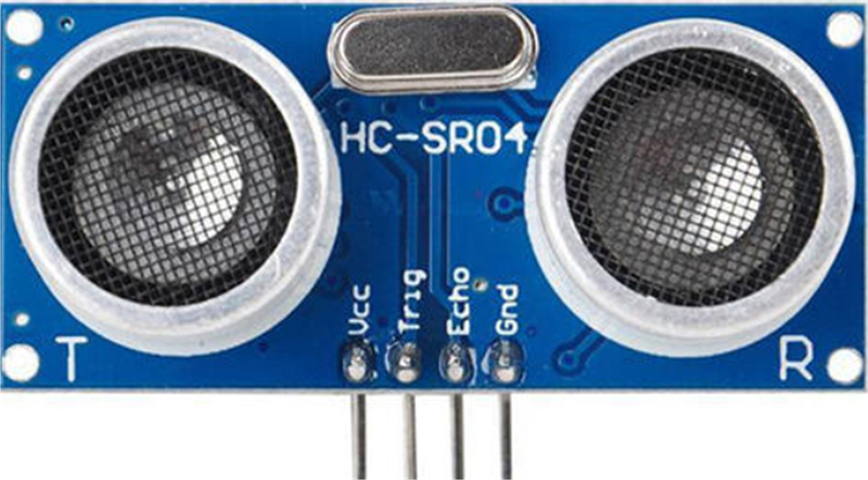
Figure 14.19 HC-SR-04 ultrasonic sensor module.
The HC-SR-04 ultrasonic sensor pair has the following specifications:
- • Operating voltage (current): 5 V (2 mA) operation
- • Detection distance: 2–450 cm
- • Input trigger signal: 10 μs TTL
- • Sensor angle: not more than 15 degrees
The sensor modules have the following pins:
| Vcc | +V power |
| Trig | Trigger input |
| Echo | Echo output |
| Gnd | Power ground |
An active piezoelectric buzzer module is used in this project. The connection between the development board and the external world is as follows:
| Development board pin | External component pin |
|---|---|
| PA2 | trig (ultrasonic sensor) |
| PE7 | echo (ultrasonic sensor) |
| PC10 | buzzer |
| mikroBUS 2 socket | USB UART Click |
Ultrasonic sensor modules are mainly used in distance-measuring applications in mobile robotics, obstacle avoidance systems, and vehicle-parking applications. The principle of operation of the ultrasonic sensor module is as follows:
- • A 10-μs high-level (+V) trigger pulse is sent to the module.
- • The module then sends out eight 40-kHz square wave signals and automatically detects the returned (echoed) pulse signal (if the signal hit an object and returned by the object).
- • If a high-level (+V) echo signal is returned, then the width of this echo signal is equal to the time taken by the ultrasonic pulse to leave and return to the sensor.
- • The distance to the object is calculated as:
Distance to object(in meters)=echo signal in seconds×speed of sound2

The speed of sound is 340 m/s, or 0.034 cm/μs
Therefore,
Distance to object(in cm)=(echo signal inμs)×0.0342

or,
Distance to object(in cm)=(echo signal inμs)×0.017

Fig. 14.20 shows the principle of operation of the ultrasonic sensor module. For example, if the width of the echo signal is 294 μs, then the distance to the object is calculated as:
- Distance to object (cm) = 294 × 0.017 = 5 cm

Figure 14.20 Operation of the ultrasonic sensor module.
The easiest way to determine the time is described in the following steps:
- 1. Send 10 μs TRIGGER pulse to ultrasonic module
- 2. Listen for Echo
- 3. Start Timer when ECHO HIGH is received
- 4. Stop Timer when ECHO goes LOW
- 5. Read Timer Value
- 6. Convert it to Distance
- 7. Process the data as required (e.g., display distance)
Fig. 14.21 shows the circuit diagram of the project. The trig and echo pins of the ultrasonic sensor are connected to port pins PA2 and PE7 of the development board, respectively. Echo output of the ultrasonic sensor is connected to port pin PE7 through potential divider resistors to drop the voltage levels to +3.3 V. The buzzer is connected to port pin PC10.

Figure 14.21 Circuit diagram of the project.
Program listing: In this project, we need to generate a 10-μs pulse to trigger the ultrasonic sensor. Additionally, the width of the echo signal must be measured in microseconds. The timer and tick count of FreeRTOS do not provide the required timing resolution. The trigger pulse is generated using the built-in function Delay_us() of the mikroC for ARM compiler. This function creates a delay in microseconds for the duration specified in the function parameter. The width of the echo pulse is measured using one of the internal timers of the STM32F407 microcontroller (this is the ARM-based microcontroller used on the Clicker 2 for STM32 development board). The timer operation of the STM32F407 microcontroller is rather complex, and it is not the intention of this book to describe it in detail here. Interested readers can find detailed information on the STM series of microcontrollers on the Internet. In this section, only parts of the timer necessary for our project are described.
The STM32F407 microcontroller provides many hardware timers. Timers 2–5 (TIM2–TIM5) are general purpose timers consisting of a 16-bit auto-reload counter, driven by a prescaler. These timers are completely independent and do not share any resources. The timers can be used to measure pulse lengths with a resolution of microseconds. The general features of these timers are as follows:
- • 16-bit up/down auto-reload counters
- • If the timer is counting up and it reaches to the value stored in TIMx_ARR (x is the timer number), then the timer resets to 0 and a new count is started.
- • If the timer is counting down, when it comes to 0, it is re-loaded to the value stored in auto-reload register TIMx_ARR.
- • A 16-bit prescaler, called TIMx_PSC (x is the timer number) is provided to divide the clock by any factor between 1 and 65535.
In this project, we shall be using a timer in what is known as the Time-Base mode, which can be used to measure the width of an event. In this mode, the counter can be configured to count up or down. By default, the counting is up. The following timer registers are used in Time-Base mode:
- • Counter register, TIMx_CNT
- • Prescaler register, TIMx_PSC
- • Auto-reload register, TIMx_ARR
Additionally, the following timer register should be configured for the correct operation of a timer:
- • Enable clock for the timer, RCC_APB1ENR.TIMxEN = 1
- • Disable counting, TIMx_CR1.CEN = 0
- • Enable counting, TIMx_CR1.CEN = 1
The steps to measure an external pulse width are as follows:
- • Enable timer clock
- • Disable counting
- • Configure the prescaler register
- • Configure the auto-reload register
- • Wait until rising edge of the pulse is detected
- • Start counting
- • Wait until falling edge of the pulse is detected
- • Stop counting
- • Read the count value
- • Convert the count value into required timing units
In this book, we will be using Timer 2 (TIM2). The clock frequency of the STM32F407 processor is set to 168 MHz (see Figure xx). TIM2 receives its clock from the APB1 bus. As shown in Figure xx, in our applications, the clock frequency of TIM2 is set to 84 MHz. The period of the timer clock is therefore:
- Period = 1 /f = 1 /84 MHz
or, period = 0.0119047 μs
If we set the prescaler value to 1000, then the timer clock period will be:
- Period = 1000 × 0.0119047, i.e., period = 11.9047 μs
We can load the timer register TIM2_CNT initially with 0 and then start the counter as soon as the rising edge of the echo pulse is detected. The counter is then stopped as soon as the falling edge of the echo pulse is detected. The value stored in register TIM2_CNT is then the duration of the pulse in terms of counter value. Multiplying this number with the clock period of 11.9047 will give us the pulse width in microseconds. Distance to the object in centimeters is then determined by multiplying the pulse width with 0.017, as shown earlier in this section. Auto-reload register can be loaded with its maximum value so that the timer does not reload.
Fig. 14.22 shows the program listing (program: ultrasonic.c). The program consists of two tasks in addition to the Idle task. Task 1 is the ultrasonic controller task, while Task 2 controls the buzzer. Communication between the two tasks is through a queue created in the main program. The operation of the program is described in the following PDL:
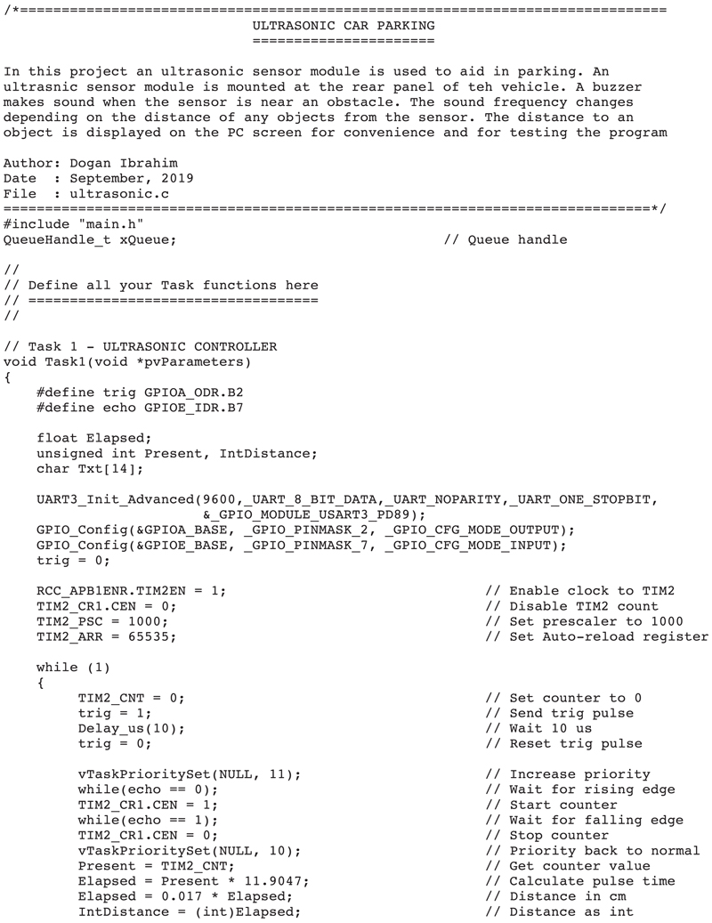
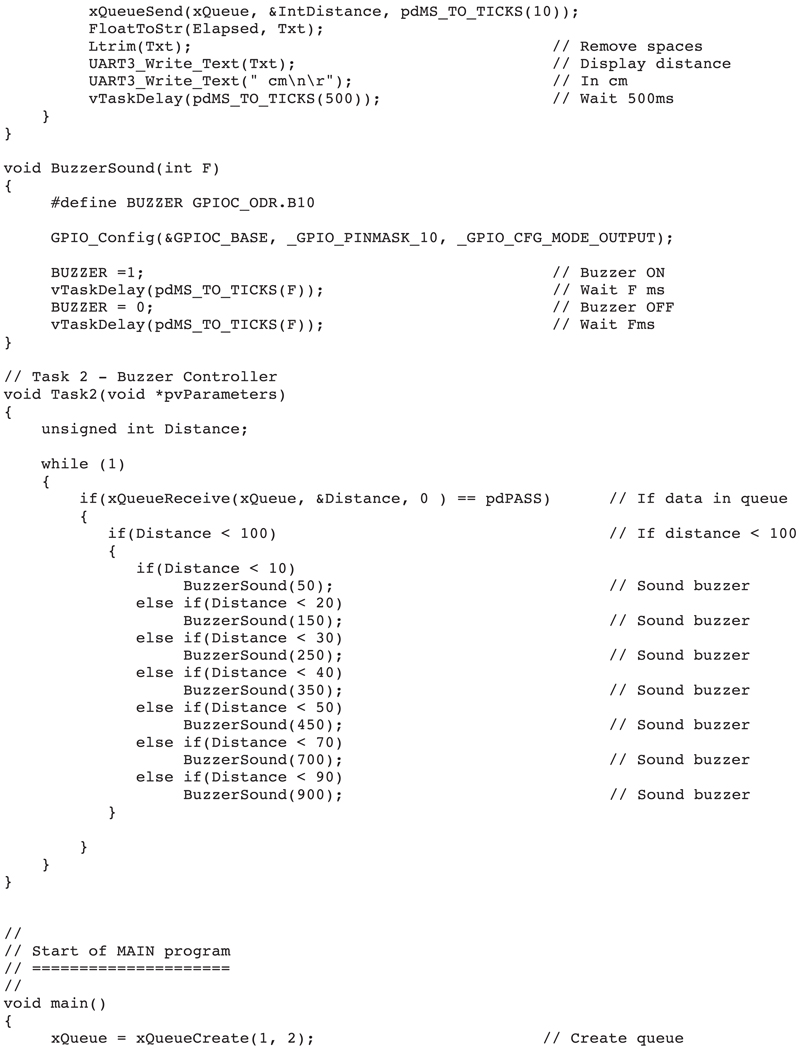
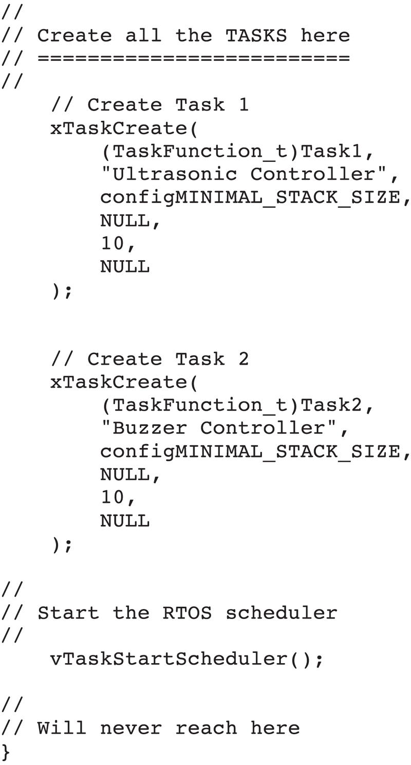
Figure 14.22 ultrasonic.c program listing.
TASK 1
- Configure trig as output and echo as input
- Initialize UART
- Configure TIM2 registers
DO FOREVER
- Set trig = 0
- Send a 10-μs pulse
- Set trig = 0
- Wait for rising edge of echo
- Start counting
- Wait for falling edge of echo
- Stop counting
- Read the timer count
- Convert the count into microseconds
- Calculate distance to the object
- Send the distance to Task 2 through a queue
- Display the distance in centimeters on screen
- Wait 500 ms
ENDDO
TASK 2
DO FOREVER
Receive the distance from the queue
IF the distance < 100 cm THEN
Call function BuzzerSound with different values to sound the buzzer
ENDIF
ENDDO
Function BuzzerSound
- Configure Buzzer port as output
- Activate the Buzzer
- Delay by the value specified by TASK 2
- Deactivate the Buzzer
- Delay by the value specified by TASK 2
Notice that the priority of TASK 1 is increased (i.e., to 11) temporarily after sending the trigger pulse to the ultrasonic sensor so that the timing is not interrupted. As soon as the falling edge of the echo pulse is detected, the priority is lowered back to its normal value (i.e., to 10):
vTaskPrioritySet(NULL, 11); // Increase the priority
while(echo == 0); // Wait for rising edge of echo
TIM2_CR1.CEN = 1; // Start timer
while(echo == 1); // Wait for falling edge of echo
TIM2_CR1.CEN = 0; // Stop the timer
vTaskPrioritySet(NULL, 10); // Priority back to normal
Activation of the buzzer depends on the distance to the object. If this distance is greater than 100 cm, then no action is taken, that is, the buzzer is not activated. If, on the other hand, the distance to the object is less than 100 cm, then the buzzer sounds at different rates depending on the distance to the object. As this distance gets smaller, the frequency of the sound generated by the buzzer is increased to let the user know that the object is very close to the sensor. This is done in Task 2 as follows:
if(Distance < 100)
{
if(Distance < 10)
BuzzerSound(50);
else if(Distance < 20)
BuzzerSound(150);
else if(Distance < 30)
BuzzerSound(250);
else if(Distance < 40)
BuzzerSound(350);
else if(Distance < 50)
BuzzerSound(450);
else if(Distance < 70)
BuzzerSound(700);
else if(Distance < 90)
BuzzerSound(900);
}
For example, if the distance to the object is less than 10 cm, the buzzer is turned ON and OFF every 50 ms. If this distance is less than 50 cm, then the buzzer is turned ON and OFF every 350 ms.
Fig. 14.23 shows the distance displayed on the PC screen.

Figure 14.23 Distance displayed on the PC screen.
As shown in Fig. 14.24, the project was constructed on a breadboard and connections were made to the development board using jumper wires.
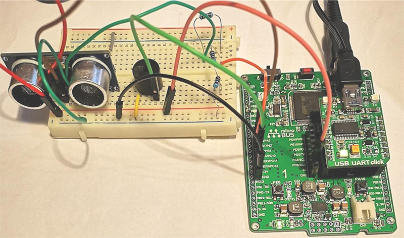
Figure 14.24 The project was constructed on a breadboard.
14.7. Project 36: stepper motor project
Description: This project shows how to use a stepper motor in a multitasking environment. In this project, a small stepper motor is used and its operation is controlled from the keyboard by entering the following commands:
- • Direction of rotation: This can be CW (clockwise) or CCW (counterclockwise).
- • Speed: This is the number of revolutions per minute (RPM).
- • Turns: Number of required to complete revolutions of the motor
- • Start: Starts the motor rotating with the specified parameters.
Aim: The aim of this project is to show how a stepper motor can be used in a multitasking environment.
Block diagram: Fig. 14.25 shows the block diagram of the project.

Figure 14.25 Block diagram of the project.
Stepper motors
Stepper motors are DC motors that rotate in small steps. These motors have several coils that are energized in sequence, causing the motor to rotate one step at a time. Stepper motors have the advantages that very precise positioning or speed control of the motor shaft can be achieved. These motors are used in many precision motion control applications, robotic arms, and mobile robots to drive the wheels.
There are basically two types of stepper motors: unipolar and bipolar.
Unipolar stepper motors
Unipolar stepper motors have four windings with a common center tap on each pair of windings (see Fig. 14.26). Therefore, there are normally five or six leads depending on whether or not the common leads are joined.

Figure 14.26 Unipolar stepper motor windings.
Unipolar motors can be rotated in reverse by reversing the sequence of applied pulses. Unipolar stepper motors can be driven in full stepping mode or in half stepping mode. Most popular drive modes are one-phase full-step, two-phase full-step, and two-phase half-step.
In one-phase full-step mode, as given in Table 14.1, each motor winding receives one pulse per step. This mode has the disadvantage that the available torque is low.
Table 14.1
| Step | a | c | b | d |
|---|---|---|---|---|
| 1 | 1 | 0 | 0 | 0 |
| 2 | 0 | 1 | 0 | 0 |
| 3 | 0 | 0 | 1 | 0 |
| 4 | 0 | 0 | 0 | 1 |

In two-phase full-step mode, as given in Table 14.2, two motor windings receive pulses per step. The advantage of this mode is that a higher torque is available from the motor.
Table 14.2
| Step | a | c | b | d |
|---|---|---|---|---|
| 1 | 1 | 0 | 0 | 1 |
| 2 | 1 | 1 | 0 | 0 |
| 3 | 0 | 1 | 1 | 0 |
| 4 | 0 | 0 | 1 | 1 |

In two-phase half-step mode, as given in Table 14.3, two motor windings sometimes receive pulses and sometimes only one winding receives a pulse. Because the motor is driven at half-step mode, eight steps are required to complete a cycle, instead of four. This mode gives higher precision, but at the expense of lower torque.
Table 14.3
| Step | a | c | b | d |
|---|---|---|---|---|
| 1 | 1 | 0 | 0 | 0 |
| 2 | 1 | 1 | 0 | 0 |
| 3 | 0 | 1 | 0 | 0 |
| 4 | 0 | 1 | 1 | 0 |
| 5 | 0 | 0 | 1 | 0 |
| 6 | 0 | 0 | 1 | 1 |
| 7 | 0 | 0 | 0 | 1 |
| 8 | 1 | 0 | 0 | 1 |

Bipolar stepper motors
Bipolar stepper motors have one winding per phase as shown in Fig. 14.27. Bipolar motor driver circuits are more complicated since the current in the windings needs to be reversed in order to rotate them in the reverse direction.
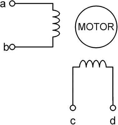
Figure 14.27 Bipolar stepper motor windings.
Table 14.4 presents the steps required to drive a bipolar stepper motor. Here, +and − signs refer to the polarity of the voltages applied to the motor leads.
Table 14.4
| Step | a | c | b | d |
|---|---|---|---|---|
| 1 | + | − | − | − |
| 2 | − | + | − | − |
| 3 | − | − | + | − |
| 4 | − | − | − | + |

Speed of a stepper motor
The speed of a stepper motor depends on the time between the pulses given to its windings. For faster speeds, the pulses must be given with shorter delays between them. If T is the time between the pulses and β is the step constant of the motor, the motor rotates by β/T steps in 1 second. Since a complete revolution is 360°, the number of revolutions in a second is β/360T. The speed of a motor is normally quoted in RPM and therefore:
RPM=60β360T

or, RPM = β/6T
where RPM is the number of revolutions per minute, β is the step constant of the motor in degrees, and T is the time between the steps in seconds.
As an example, assume that the step constant of a stepper motor is 10 degrees (β = 10°). If we want to rotate this motor at a speed of 1000 RPM (assuming that the motor is capable of rotating this fast), the time between the pulses is calculated as:
T=β6RPM=106×1000=1.66 ms

Therefore, the pulses between each step must be 1.66 ms.
Movement of the motor shaft
In some applications, we may want the motor shaft to rotate a specified amount and we need to know how many pulses to send to the motor. If β is the step constant of the motor and we want the shaft to rotate by v degrees, the required number of pulses is given by:
n=νβ

For example, assuming that the step constant is 5° (β = 5) and that we want the motor to rotate by 200 degrees, the required number of steps is:
n=2005=40

Motor rotation time
Sometimes we may want the motor to rotate for a given time and we want to know how many pulses to apply to the motor. If T is the time between the pulses and we send n pulses to the motor, the rotation time T0 can be calculated as follows:
- T0 = nT
For example, assuming that the time between the pulses is 1 ms, if we want the motor to rotate for 5 seconds, the required number of pulses is given by:
N=T0T=50.001=5000

Stepper motors can be driven by several ways, such as using bipolar transistors, MOSFET transistors, or integrated circuits such as L293, ULN2003, and so on. The Stepper Click boards manufactured by mikroElektronika can be plugged directly to the mikroBUS sockets of the Clicker 2 for STM development board and there are versions for driving both unipolar and bipolar stepper motors. An example unipolar stepper motor driver, called the Stepper 3 Click, is shown in Fig. 14.28.

Figure 14.28 Stepper 3 Click board for unipolar stepper motors.
Circuit diagram: In this project, a small 28BYJ-48 type unipolar stepper motor (see Fig. 14.29) is used. This motor has the following specifications:
| Rated voltage | 5 V |
| Number of phases | 4 |
| Gear ratio | 64 |
| Frequency | 100 Hz |
| Step angle | 11.25° / step |
| Maximum speed | 18 RPM |
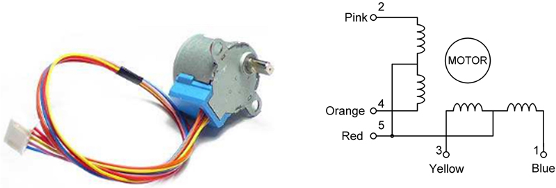
Figure 14.29 28BYJ-48 unipolar stepper motor.
In this project, the motor is driven using a ULN2003 IC-based motor driver module shown in Fig. 14.30 together with its circuit diagram. This module has four input connections labeled IN1, IN2, IN3, and IN4. The motor is plugged into the socket in the middle of the module. Four LEDs, labeled A, B, C, and D, are provided to see the status of the motor windings. Power to the module is applied through the bottom two header pins at the right-hand side of the module. The LEDs can be enabled by shorting the two top header pins at the right-hand side of the module. In this project, the module was powered from an external +5 V DC power supply for the motor (it is recommended to use an external +5 V power supply and not use the Clicker 2 for STM32 +5 V power supply, as this may not provide enough current to drive the motor).
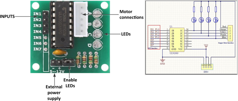
Figure 14.30 ULN2003 motor driver module.
A USB UART Click board is connected to mikroBUS Socket 2 as in the previous projects that communicate with a PC.
Fig. 14.31 shows the circuit diagram of the project. Port pins PA2, PE7, PE8, and PC10 of the Clicker 2 for STM32 development board are connected to driver module inputs IN1, IN2, IN3, and IN4, respectively. The project with the stepper motor is shown in Fig. 14.32
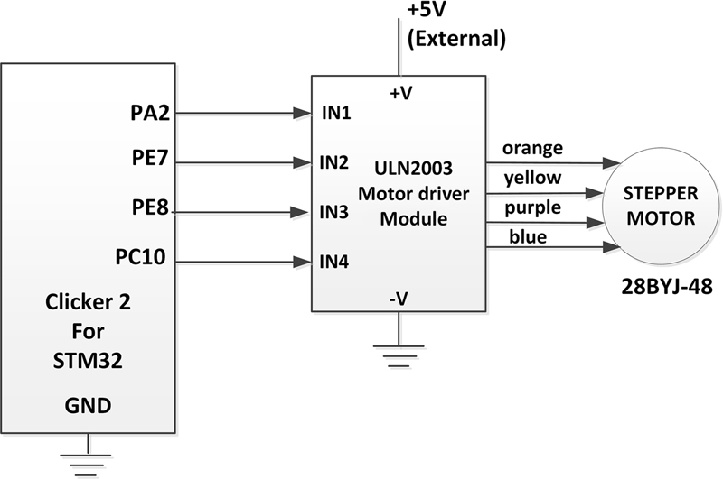
Figure 14.31 Circuit diagram of the project.
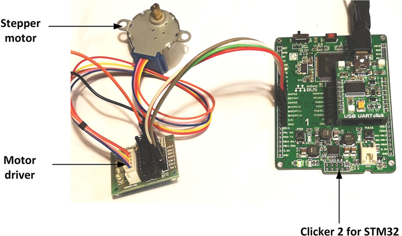
Figure 14.32 Project with the stepper motor.
Program listing:
- The 28BYJ-48 stepper motor can either be operated in full-step or in half-step modes.
Full-step mode
In full-step mode, there are four steps per cycle and 11.25 degrees/step, corresponding to 32 steps per one revolution of the internal motor shaft. Because the motor is geared with a gear ratio of 64 (in fact, the gear ratio is 63.68395), the number steps for one external complete revolution is 2048 steps/revolution (512 cycles with four steps per cycle).
Table 14.5 presents the motor winding sequence for the full-step mode (this sequence is repeated. Reversing the sequence reverses the direction of rotation).
Table 14.5
| Step | 4 (orange) IN1 |
3 (yellow) IN2 |
2 (pink) IN3 |
1 (blue) IN4 |
|---|---|---|---|---|
| 1 | 1 | 1 | 0 | 0 |
| 2 | 0 | 1 | 1 | 0 |
| 3 | 0 | 0 | 1 | 1 |
| 4 | 1 | 0 | 0 | 1 |

Half-step mode
The half-step mode with eight steps per cycle is recommended by the manufacturer. In half-step mode, we have 5.625 degrees/step, corresponding to 64 steps per one revolution of the internal motor shaft. Because the motor is geared with a gear ratio of 64, the number of steps for one external complete revolution is 4096 steps/revolution (512 cycles with eight steps per cycle).
Table 14.6 presents the motor winding pulse sequence for the half-step mode (this sequence is repeated. Reversing the sequence reverses the direction of rotation).
Table 14.6
| Step | 4 (orange) IN1 |
3 (yellow) IN2 |
2 (pink) IN3 |
1 (blue) IN4 |
|---|---|---|---|---|
| 1 | 1 | 0 | 0 | 0 |
| 2 | 1 | 1 | 0 | 0 |
| 3 | 0 | 1 | 0 | 0 |
| 4 | 0 | 1 | 1 | 0 |
| 5 | 0 | 0 | 1 | 0 |
| 6 | 0 | 0 | 1 | 1 |
| 7 | 0 | 0 | 0 | 1 |
| 8 | 1 | 0 | 0 | 1 |

In this project, the stepper motor is controlled in Full-Step mode and Fig. 14.33 shows the program listing (program: stepperfull.c). The program consists of two tasks in addition to the Idle task.
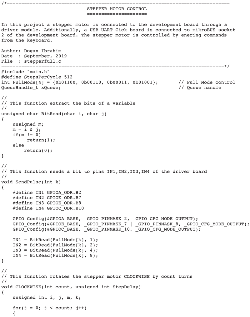

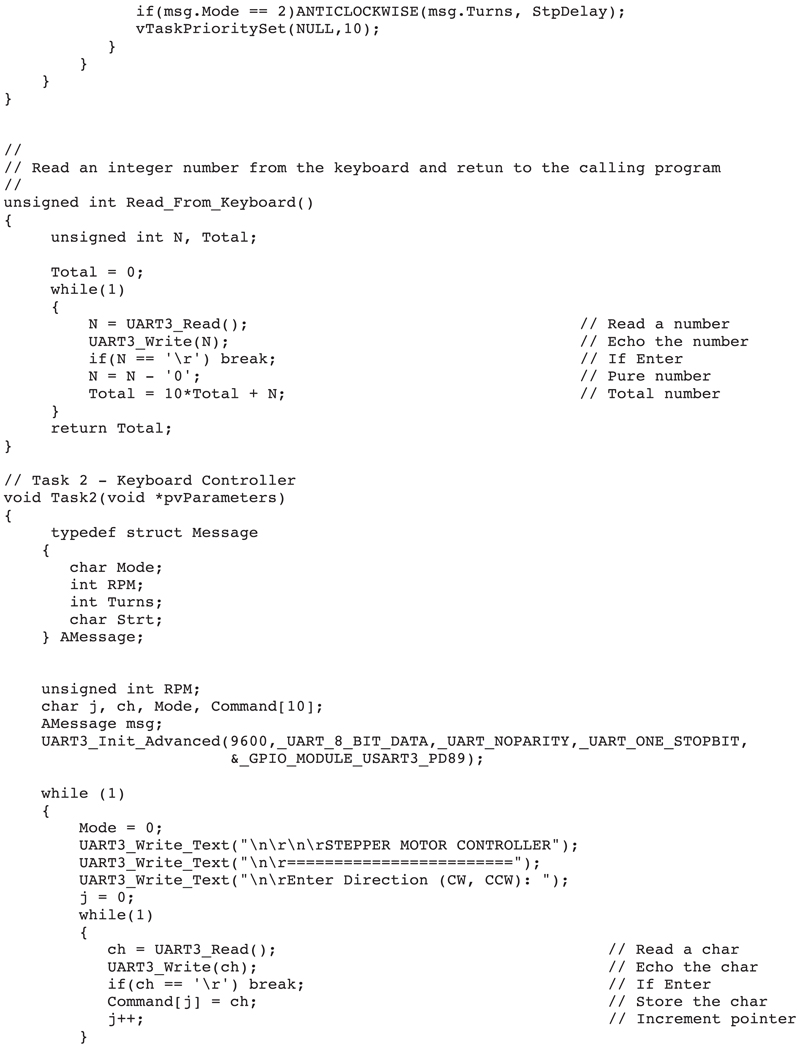

Figure 14.33 stepperfull.c program listing.
TASK 1
Task 1 controls the stepper motor. Here, the motor is stopped by default when the program starts. As described earlier, the speed depends on the delay inserted between each step. In Full-step mode, there are 2048 steps in a complete revolution. The motor speed in RPM is given by the following equation:
RPM=60×1032048×T

or,
RPM=29.3T

where RPM is the motor speed in revolutions per minute and T is the delay between each step in milliseconds. We usually want to know how much delay to insert between each step so that the required number of revolutions can be achieved. This is given in milliseconds by:
T=29.3RPM

At the beginning of Task 1, motor driver pins IN1, IN2, IN3, and IN4 are assigned to port pins PA2, PE7, PE8, and PC10, respectively. Then, the motor speed is stopped, waiting to receive a command from the keyboard, sent by Task 2. The pulses to be sent to the motor in Full-mode clockwise direction are stored in character array FullMode in binary format, as indicates in Table 14.5. That is,
- int FullMode[4] = {0b01100, 0b00110, 0b00011, 0b01001};
Task 1 receives the required rotational parameters from Task 2 through a queue. The data in the queue are passed using a structure with the following items:
typedef struct Message
{
char Mode;
int RPM;
int Turns;
char Strt;
} AMessage;
The Mode specified the direction of rotation, where 1 corresponds to clockwise and 2 corresponds to anticlockwise. The step delay is calculated by dividing 29.3 by the required RPM as described earlier. Task 1 then calls function CLOCKWISE or ANTICLOCKWISE depending on the value of Mode.
Function CLOCKWISE sends four pulses to the motor with a delay of StepDelay milliseconds between each pulse. This ensures that the motor speed is as required. This is repeated StepsPerRevolution times so that the motor makes a complete revolution. This whole process is then repeated count times, which is the number of times we want the motor to rotate complete revolutions. Function ANTICLOCKWISE is similar to CLOCKWISE, but here the steps are sent in reverse order to the motor. The step delay is implemented by calling the built-in function vDelay_ms().
Both functions CLOCKWISE and ANTICLOCKWISE call function SendPulse() which configures the output pins and sends the required bit patterns to output pins IN1, IN2, IN3, and IN4. Function BitRead() extracts the bits from a variable. For example, if the input parameters to this function (i and j) are 0b00011 and 2, respectively, then the function will return 1, which is the bit at position 2 of the data.
TASK 2
This task receives commands from the keyboard and sends these commands to Task 1 so that the motor is controlled as required. At the beginning of this task, the UART is initialized to operate at 9600 baud. The user is prompted to enter responses to the following questions:
- Enter Direction (CW, CCW):
- Enter the speed (RPM):
- How many turns?:
- Start (1 = Yes, 0 = No):
After receiving the required rotational parameters, if the response to Start is 1, then these parameters are sent to Task 1 through a queue.
Notice that this is a real-time application where the correct control of the stepping motor requires precision microsecond timing of the pulses sent to the motor. Normally, this is not possible with the FreeRTOS since the task can be interrupted while sending pules to the motor. For this reason, it was necessary to increase the priority of Task 1 just before sending pulses to the motor via functions CLOCKWISE and ANTICLOCKWISE. The priority is lowered back to its normal value of 10 after the motor stops.
Fig. 14.34 shows a typical run of the motor with the motor rotational parameters entered from the keyboard.
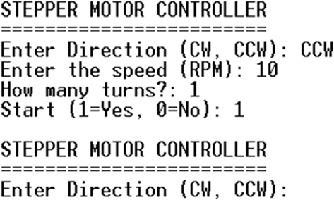
Figure 14.34 Entering the motor rotational parameters.
14.8. Project 37: communicating with the Arduino
Description: In this project, an Arduino computer reads the ambient temperature from an analog sensor and sends the readings to the Clicker 2 for STM32 development board over the serial link every second. An LCD is connected to the development board to display the temperature. The user determines the LCD data refreshing rate by entering a command from the keyboard.
Aim: The aim of this project is to show how the Clicker 2 for STM32 development board can receive data from its serial port and display these data on an LCD in a multitasking environment.
Block diagram: Fig. 14.35 shows the block diagram of the project. An L35DZ type analog temperature sensor is connected to one of the analog input ports of the Arduino. Software UART is used on the Arduino and a pin is configured as serial input/output. Serial output of the Arduino is connected to one of the serial inputs of the development board. Additionally, an LCD is connected to the development board to display the temperature. The display refresh rate is set initially to 1 second, but it can be changed from the keyboard.

Figure 14.35 Block diagram of the project.
Circuit diagram: The circuit diagram of the project is shown in Fig. 14.36. In this project, an Arduino Uno is used. The output pin of the LM35DZ temperature sensor is connected to analog input pin A0 of the Arduino. Pins 2 and 3 are configured as RX and TX pins of software serial port, respectively. Pin 3 (TX) is connected to pin PD6 (UART2 RX pin) of the development board. This pin is easily accessible at the mikroBUS Socket 1 header. The LCD is connected to the development board as in the previous projects using an LCD. The USB UART Click board is connected to mikroBUS Socket 2 and is interfaced to the PC through a mini USB cable. A terminal emulation software (e.g., HyperTerm, Putty) is run on the PC to communicate over the serial link with the development board.
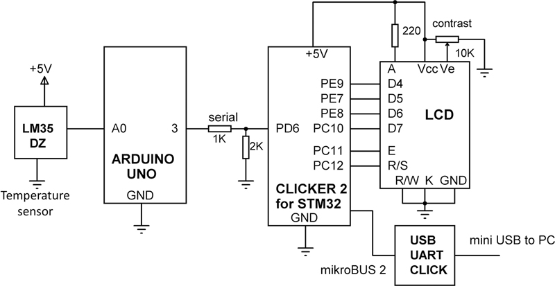
Figure 14.36 Circuit diagram of the project.
Notice that the output port signal levels of the Arduino Uno are +5 V and this is too high for the inputs of the Clicker 2 for STM32 development board. Therefore, a resistive potential divider circuit consisting of two resistors is used to lower the voltage to around +3.3 V before connecting to pin PD6 of the development board.
Programs
The operation of the programs is described below in PDL:
Arduino
Configure pins 3 and 4 as software UART
DO FOREVER
- Read temperature from analog port A0
- Convert temperature to Degrees Centigrade
- Send temperature over the serial port
- Wait 1 second
ENDDO
Task 1
- Configure UART
- Configure LCD interface
- Initialize LCD
- Set refresh-rate to 2 seconds
DO FOREVER
IF new refreshing rate is available THEN
- Read refresh-rate from the queue
ENDIF
- Wait refresh-rate seconds
- Read temperature from serial port
- Display temperature on LCD
ENDDO
Task 2
Configure UART
DO FOREVER
- Read new refreshing-rate from the keyboard
- Write the new refreshing rate to the queue
ENDDO
The details of each task are given as follows.
Arduino Uno program listing: The Arduino Uno program is very simple and its listing is shown in Fig. 14.37 (program: arduinotemp). At the beginning of the program, the software serial port is configured. Inside the main program loop, the temperature is received from the LM35DZ sensor chip and is converted into Degrees Centigrade. The measured temperature of the LM35DZ is directly proportional to the output voltage and is given by:
T=Vo10


Figure 14.37 Arduino Uno program listing.
where T is the measured temperature and Vo is the output voltage in millivolts. The temperature readings are sent over the serial link to the Clicker 2 for STM32 development board every second. You should compile and then upload the code to your Arduino Uno.
Clicker 2 for STM32 program listing: This program consists of two tasks in addition to the Idle task. At the beginning of the program, the interface between the LCD and the development board is defined. Task 1 is the Serial Port Controller which receives the temperature readings from the Arduino over the serial link and displays these readings on the LCD. Task 2 is the keyboard controller which receives the commands from the keyboard. The details of each task are described below:
TASK 1
At the beginning of this task, the UART2 baud rate is set to 9600 and port pins PD5 and PD6 are configured as the UART2 TX and RX pins, respectively. The LCD data refreshing rate is called RefreshRate and by default it is set to 1000 ms at the beginning of this task. The task receives new refreshing rates from Task 2 through a queue. The refreshing rate is displayed at the top row of the LCD. The program receives the temperature value from the Arduino through serial port UART2 and displays it at the second row of the LCD.
TASK 2
At the beginning of this task, the UART3 baud rate is set to 9600 and port pins PD8 and PD9 are configured as the UART3 TX and RX pins, respectively. The task then prompts the user to enter the required LCD data refresh rate and send the received value to Task 1 through the queue. Function Read_From_Keyboard() is used to read an integer number from the PC keyboard through UART 3 and the USB UART Click board.
Fig. 14.38 shows the program listing (program: arduinostm.c).
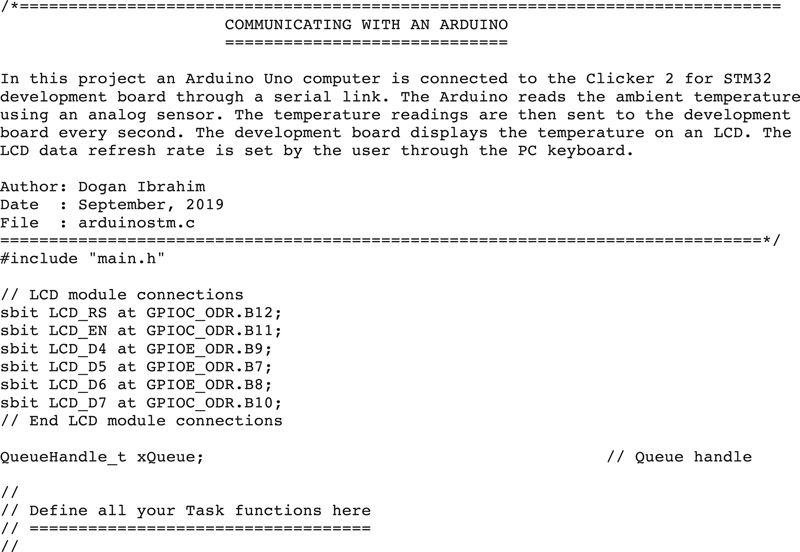


Figure 14.38 arduinostm.c program listing.
Fig. 14.39 shows the screen where the LCD data refreshing rate was set to 10000 ms (10 seconds) and then to 5000 ms. The data on the LCD are shown in Fig. 14.40.

Figure 14.39 Example display on the PC screen.
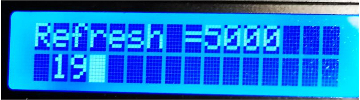
Figure 14.40 Data displayed on the LCD.
14.9. Summary
In this chapter, we have developed several projects to illustrate how to use the various FreeRTOS functions in multitasking projects.
In the next chapters, we shall be looking at some other important functions of FreeRTOS and see how they can be used in projects.
..................Content has been hidden....................
You can't read the all page of ebook, please click here login for view all page.