Buggy is a four-wheeled mobile robot developed by mikroElektronika for use mainly in educational establishments to teach the principles of robotic applications. The robot is like a real car, having head lights, brake lights, and signal turning lights. Users can develop programs to control all the lights and the motors of the robot. This chapter describes the basic parts of the robot and gives several projects to show how the lights and the motors can easily be controlled. The Clicker 2 for STM32 development board is used in all the projects. A project is given with complete program listing to show how a multitasking FreeRTOS-based obstacle avoiding robot can be developed using various sensors and a buzzer. Another project describes in detail how the movements as well as the lights of the robot can be controlled remotely using radiofrequency (RF) transmitter/receiver modules by entering commands from a PC keyboard.
Keywords
robot
mobile robot control
buggy
STM32
FreeRTOS
buggy control
tRF click
22.1. Overview
In this chapter, we develop some other multitasking projects based on using a four-wheel mobile robot, that is, a Buggy using the Clicker 2 for STM32 development board and the FreeRTOS application program interface (API) functions. The Buggy chosen for this project is the one manufactured by miktoElektronika. Full details of this buggy are given in the next sections of this chapter.
22.2. The Buggy
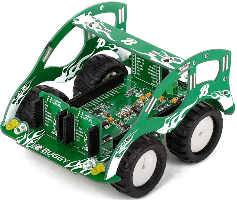
The Buggy used in the projects in this chapter is a four-wheel mobile robot manufactured by mikroElektronika (www.mikroe.com). Fig. 22.1 shows a picture of the Buggy in assembled form (the buggy is sold in parts and needs to be assembled before it can be used).
Figure 22.1The Buggy.
Basically, the Buggy consists of a four-wheel mobile robot with a Clicker 2 type microcontroller development board (see mikroElektronika website) plugged-in inside the Buggy. In this project, a Clicker 2 for STM32 type development board is plugged-in inside the Buggy. Additionally, the Buggy contains four motors to drive the wheels and includes associated electronics to control these motors. Several mikroBUS sockets are provided on the buggy so that the user can simply plug-in Click boards for various sensor- and actuator-based applications. Lights in the form of LEDs are provided at the front and rear of the Buggy that can be controlled from software. The operation of the Buggy is programmed by programming the Clicker 2 for STM32 development board using the mikroC Pro for ARM compiler and the IDE.
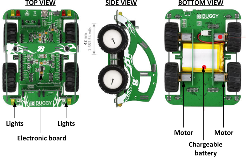
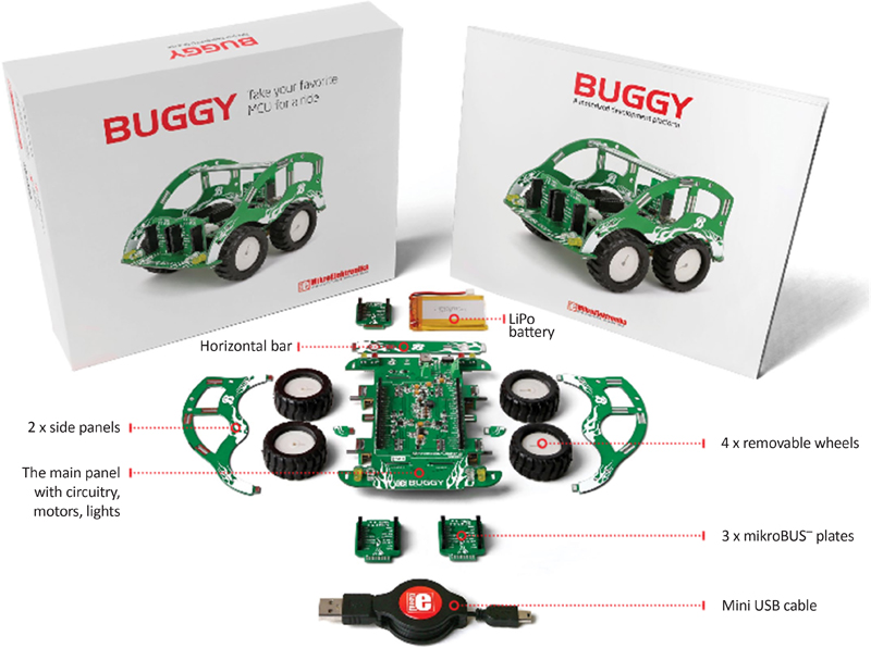
Fig. 22.2 shows the basic parts of the Buggy. Parts of the buggy in unassembled form as sold by the distributors are shown in Fig. 22.3.
Figure 22.2Basic parts of the Buggy.
Figure 22.3Buggy in unassembled form.
Before controlling the Buggy, it is necessary to know in detail all the parts mounted on it. The front of the Buggy is equipped with the following components (see Fig. 22.4):
• Two microBUS socket plates
• 2× Front signal lights (Yellow)
• 2× front headlights (White)
Figure 22.4Front of the Buggy.
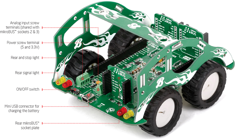
The rear of the Buggy is equipped with the following components (see Fig. 22.5):
• Analog input (screw terminal)
• Power (screw terminal)
• 2× stop lights (Red)
• 2× signal lights (Yellow)
• ON/OFF switch
• miniUSB connector (for charging the battery)
• Power ON LED (Green)
• Battery charging LED (Red)
• mikroBUS socket plate
Figure 22.5Rear of the Buggy.
The main Buggy PCB contains the motors for the four wheels, battery charger circuitry, screw terminals for power and analog input, ON/OFF switch, signal lights, headlights, stop lights, connector to plug-in a Clicker 2 development board (in this project the Clicker 2 for STM32 development board is used), and mikroBUS socket plates.
22.3. Wheel motors
The Buggy has a differential motor drives, controlled by two DRV833RTY type motor drivers (U6 and U7), one for each side of the Buggy. DRV833RTY is a dual H-bridge type motor driver chip that can be used for bi-directional control of a motor. Steering is achieved when the relative rate of rotation between the left and right sides are varied. When one pair of wheels is put in reverse while the other is in normal mode, the Buggy will start to spin. To prevent the motors from drawing too much current from the battery, a few resistors are placed to limit the current draw. Each motor can draw a maximum of 400 mA, for a total of 1.6 A when all four motors are running. Fig. 22.6 shows the motors assembly.
Figure 22.6The motor assembly.
With the Clicker 2 for STM32 development board plugged-in to the Buggy, the following port pins control the wheel motors:
Motor pin
Description
Clicker 2 for STM32 pin
PWM-A
Left-side motor
PB9
PWM-B
Left-side motor
PB8
PWM-C
Right-side motor
PE5
PWM-D
Right-side motor
PB0
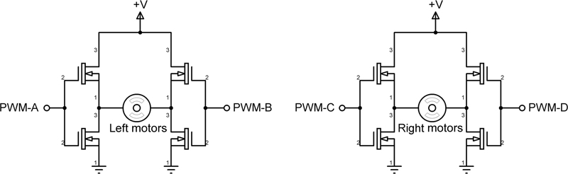
The motor direction, and hence the direction of the Buggy, is controlled by activating the correct pins of the motor driver chip. Fig. 22.7 shows how an H-bridge type motor driver operates. The inputs of the driver are connected together and the motor is connected as shown in the figure. When, for example, pin PWM-A is at logic 1 and pin PWM-B is at logic 0, then the motor rotates in one direction. When pin PWM-A is at logic 0 and pin PWM-B is at logic 1, then the motor rotates in the opposite direction. The two left motors are connected to pins PWM-A and PWM-B. Similarly, the two right motors are connected to pins PWM-C and PWM-D of the development board. By activating the pins in the correct sequence, we can control the movements of the Buggy as given in the following table.
In the forward and backward directions, both left and right motors are activated at the same speed. When turning left, we can stop the left motors and only activate the right motors. Similarly, when turning right, we can stop the right motors and activate only the left motors. Notice that in left and right turn operations, the motors can be activated at reduced speed (e.g., half speed or even lower).
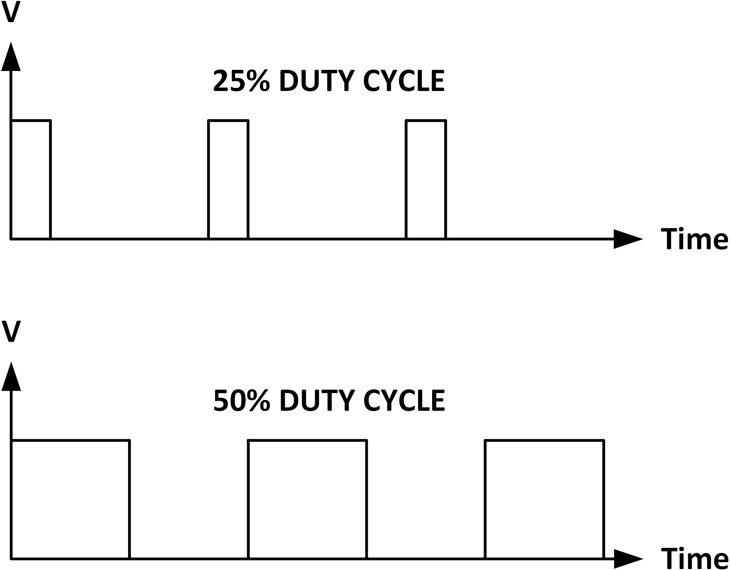
The motors are activated by sending PWM (pulse width modulated) signals to them (Fig. 22.8). A PWM signal is a positive square wave signal with a fixed period. The Duty Cycle of the signal is the ratio of the duration of the positive pulse to the period of the signal. By varying the duty cycle, we can effectively vary the average voltage supplied to the motors, and this is how the speed of the Buggy can be changed. Fig. 22.9 shows example PWM waveforms with 25% and 50% duty cycles.
Figure 22.8PWM waveform.
Figure 22.9PWM waveform with different duty cycles.
Most microcontrollers have built-in PWM generator modules. The STM32F407 microcontroller used in this book supports a large number of PWM modules. Using the mikroC Pro for ARM compiler, the PWM channels on the STM32F407 microcontroller are configured using the following built-in library functions:
PWM_TIMn_Init()
PWM_TIMn_Set_Duty()
PWM_TIMn_Start()
PWM_TIMn_Stop()
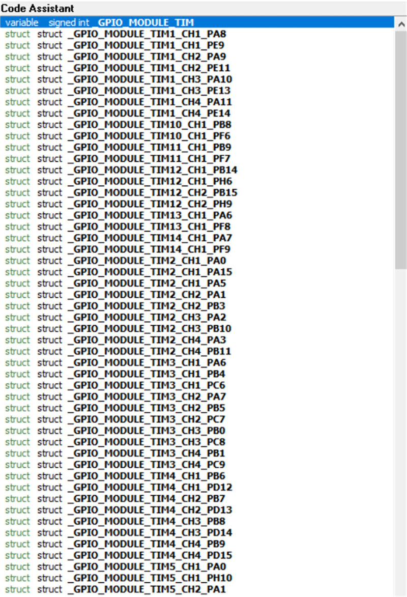
PWM_TIMn_Init(): This function is used to initialize a timer module for PWM operation, where n is the chosen timer module number. The frequency of the required PWM signal must be supplied to the function. The function returns an integer which is equal to the calculated maximum period of the PWM waveform. A timer between 0 and 17 can be selected, but it is important to make sure that the chosen output pin supports PWM operation with the chosen timer. Some of the available timers and output pin names supported by STM32F407 microcontroller are shown in Fig. 22.10 (complete list can be obtained by typing _GPIO_MODULE_TIM inside the compiler and pressing keys Cntrl + Space).
Figure 22.10Some supported timers and output pin names.
The example library function call below shows how the PWM frequency can be set to 1000 Hz for timer 11. The maximum period is returned and saved in variable called PWMA:
PWMA = PWM_TIM11_Init(1000);
PWM_TIMn_Set_Duty(): This function changes the duty cycle of the PWM waveform. The required duty cycle, its mode, and the channel number must be supplied to the function. The duty cycle can be expressed as a percentage of the maximum value returned by call to function PWM_TIMn_Init(). The mode can be _PWM_INVERTED or _PWM_NON_INVERTED. The PWM channel number can be selected from the list given in Fig. 22.10. The example below sets the duty cycle to 50% (PWMA / 2) with non-inverted waveform for channel 1, using timer 11:
PWM_TIMn_Start(): This function starts generating PWM waveform on the selected output pin, channel, and the timer. The channel number and the output pin names must be supplied to the function. The example below starts PWM on output pin PB9, using timer 11 with channel 1 (see Fig. 22.10 on how to select an output pin, timer, and channel number):
PWM_TIMn_Stop(): This function stops the PWM. The channel number must be supplied to the function. The example below shows how PWM on channel 1 can be stopped:
PWM_TIM11_Stop(_PWM_CHANNEL1);
We will be seeing in a later project how to configure the wheel motors to move the Buggy forward, backward, and turning left and right.
22.4. Lights (LEDs)
Just like a real car, the Buggy has a set of front and rear lights for signaling and lighting the way. All of these lights are programmable from software. The lights are grouped as follows:
• The pair of white LEDs on the front are headlights with two modes of brightness.
• The Red LEDs at the rear are brake lights, having two modes of brightness.
• The two pair of Yellow LEDs at the front and rear are the signal lights.
With the Clicker 2 for STM32 development board plugged-in to the Buggy, the following port pins control the lights:
Light
Description
Clicker 2 for STM32 pin
Brake
Rear
PE1
Signal
Right
PE2
Signal
Left
PC4
Head lights
Front (main beam)
PB6
Head lights
Front (low intensity)
PE3
Head lights and brake lights have two brightness levels as shown by the following combinations:
Main beam + low intensity: gives bright head lights and normal brightness brake lights
Low intensity only: gives low-intensity head lights and normal intensity brake lights
Break light + low intensity: gives bright brake lights and normal intensity head lights
Further details and the complete circuit diagram of the Buggy can be obtained from the Buggy manual available at the following website:
Description: This project shows how the Buggy lights can be controlled using functions. In this project, the Buggy lights are controlled as follows:
• Flash left signal lights 10 times at a rate of 250 ms
• Flash right signal lights 10 times at a rate of 250 ms
• Turn ON brake lights
• Wait 1 second
• Turn OFF brake lights
• Turn ON head lights
• Wait 1 second
• Turn OFF head lights
Aim: The aim of this project is to make the user familiar with controlling the Buggy lights.
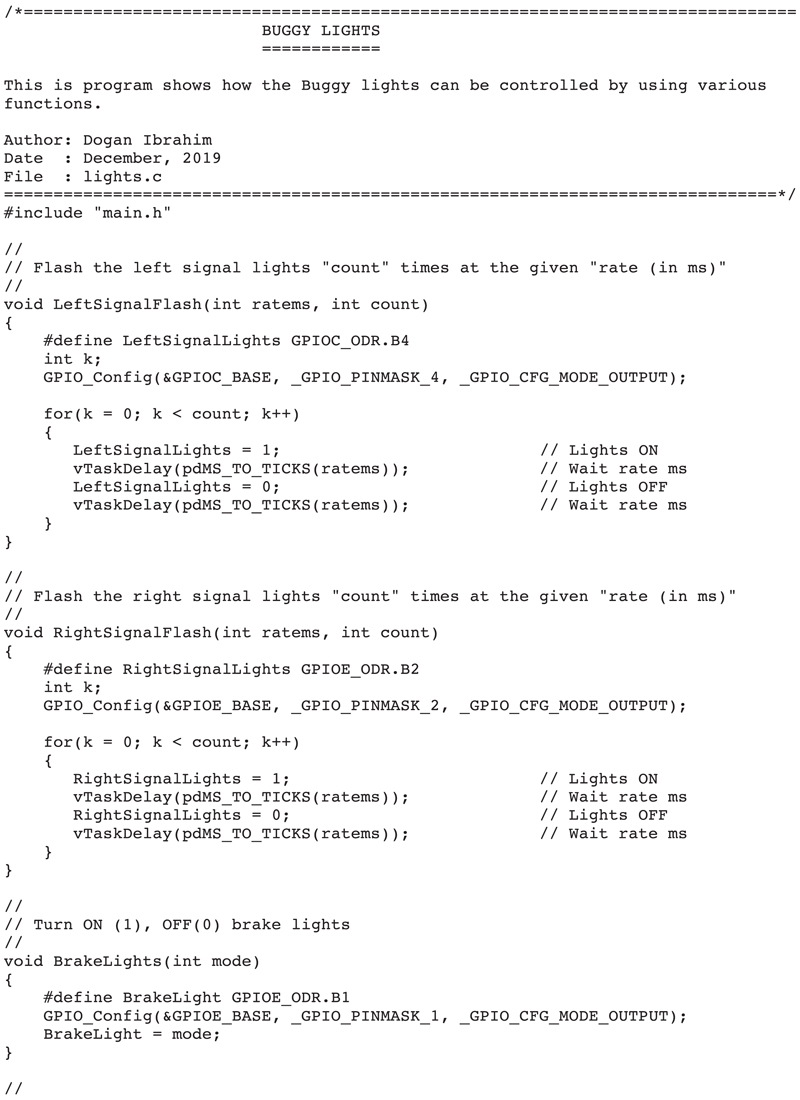
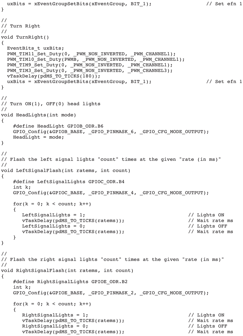
Program listing: Fig. 22.11 shows the program listing (lights.c). The program uses the following functions to control the lights:
LeftSignalFlash(int ratems, int count): This function flashes the left signal lights count times at a rate of ratems milliseconds.
RightSignalFlash(int ratems, int count): This function flashes the right signal lights count times at a rate of ratems milliseconds.
BrakeLights(int mode): This function turns ON (mode = 1) or OFF (mode = 0) the brake lights.
HeadLights(int mode): This function turns ON (mode = 1) or OFF (mode = 0) the head lights.
Figure 22.11lights.c program listing.
22.6. Project 58: controlling the Buggy motors
Description: This project shows how the Buggy motors can be controlled using functions to move the Buggy forward, backward, and to turn left and right. In this project, the Buggy movement is controlled as follows:
• Move the Buggy forwards for 1 second at half speed
• Stop and wait 5 seconds
• Turn the Buggy left
• Stop and wait 5 seconds
• Move the Buggy backward for 1 second at half speed
• Stop and wait for 5 seconds
• Move the Buggy right
• Stop and wait 5 seconds
• Move the Buggy forward for 1 second at half speed
• Stop
Aim: The aim of this project is to make the user familiar with controlling the Buggy movements.
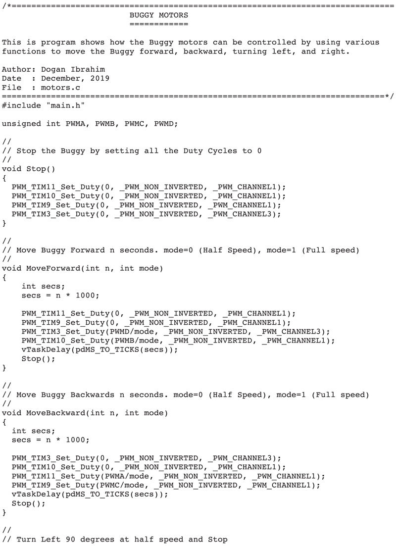
Program listing: Fig. 22.12 shows the program listing (motors.c). The program uses the following functions to control the Buggy movements:
Figure 22.12motors.c program listing.
MoveForward(int n, int mode): This function moves the Buggy forward for n seconds and then stops it. Mode specifies the speed of the Buggy as follows:
Mode
Speed
1
Full speed
2
Half speed
3
Quarter speed, etc.
MoveBackward(int n, int mode): This function moves the Buggy backward for n seconds and then stops it. Mode specifies the speed of the Buggy as above.
TurnLeft(): This function turns the Buggy left and then stops it.
TurnRight(): This function turns the Buggy right and then stops it.
Stop(): This function sets all the duty cycles to 0, thus stopping all the motors.
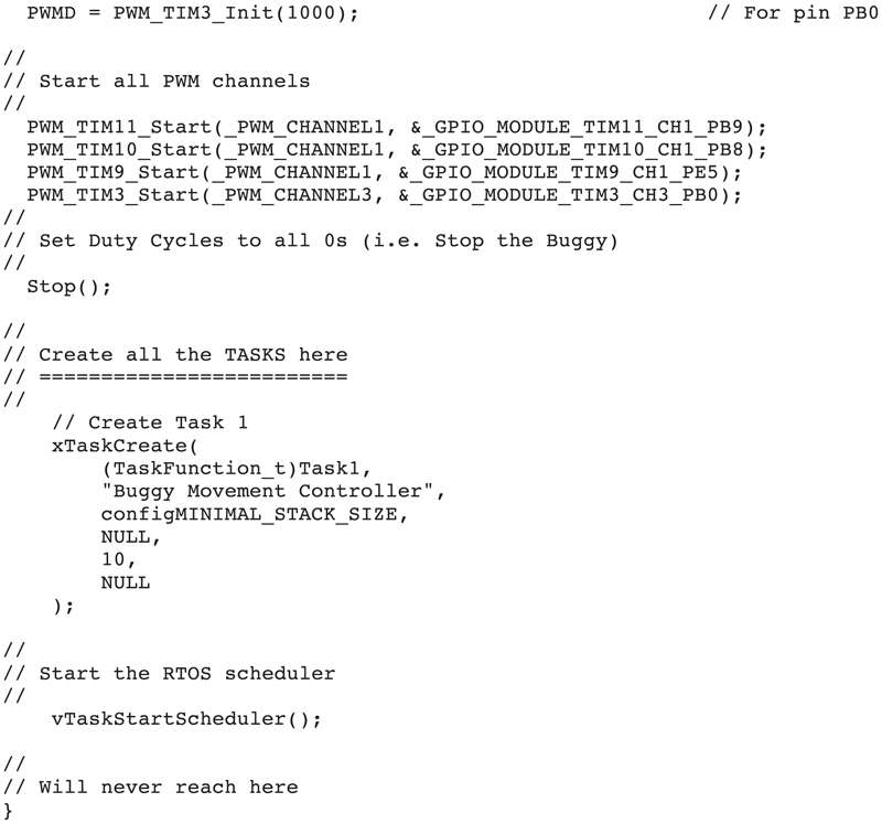
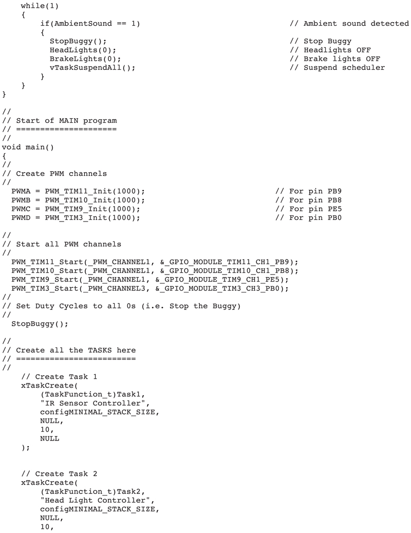
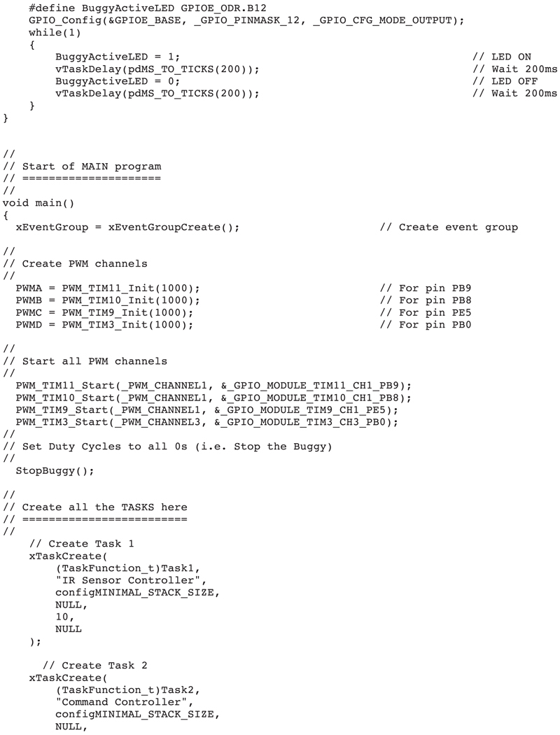
Inside the main program, the PWM channels are initialized as follows (check with Fig. 22.10 for pin numbers and channels):
PWMA = PWM_TIM11_Init(1000); // For pin PB9
PWMB = PWM_TIM10_Init(1000); // For pin PB8
PWMC = PWM_TIM9_Init(1000); // For pin PE5
PWMD = PWM_TIM3_Init(1000); // For pin PB0
According to Fig. 22.10, the PWM channel and timer assignments for the motor pins are as follows:
Pin
Pin name
Channel
Timer
Description
PB9
PWM-A
1
11
Left-side motor
PB8
PWM-B
1
10
Left-side motor
PE5
PWM-C
1
9
Right-side motor
PB0
PWM-D
3
3
Right-side motor
The PWM signals were then started on each channel using the following functions:
The MoveForward function moves the Buggy forward for the specified number of seconds. In this function, the duty cycles of PWM-A (PWM_TIM11) and PWM-C (PWM_TIM9) are set to 0. The duty cycles of PWB-B (PEM_TIM10) and PWM-D (PWM_TIM3) can be set by argument mode of the function as described earlier.
The MoveBackward function is similar to MoveForward, but here, the duty cycles of PWM-B (PWM_TIM10) and PWM-D (PWM_TIM3) are set to 0. The duty cycles of PWM-A (PWM_TIM11) and PWM-C (PWM_TIM9) can be set by argument mode of the function as described earlier.
The TurnLeft function turns the Buggy 90 degrees to its left. Here, the duty cycles of PWM-A, PWM-B, and PWM-C are set to 0, and the duty cycle of PWM-D is set to full mode, that is, PWMD. It was found by experimenting that 200 ms turning action results in 90 degrees turning of the Buggy. Using a longer delay will turn the Buggy further. Similarly, using a smaller delay will turn the Buggy less than 90 degrees.
The TurnRight function is similar to TurnLeft, but here the duty cycles of PWM-A, PWM-C, and PWM-D are set to 0, and the duty cycle of PWM-B is set to full mode.
It is important to notice that PWM must be enabled in the Library Manager before the program can be compiled.
22.7. Project 59: obstacle avoiding Buggy
Description: This is a multitasking obstacle avoiding Buggy project. An infrared (IR) distance sensor is mounted in-front of the Buggy. The Buggy moves forward, and if it detects an obstacle on its way, it turns left by 90 degrees with the hope of avoiding the obstacle. A buzzer is connected to the Buggy which sounds when an obstacle is on its way. The left signal lights are flashed to indicate when the Buggy is about to turn left. Additionally, a light sensor (ambient click) is mounted on the Buggy which detects when it is dark and turns ON the head lights automatically. A sound sensor module detects ambient sounds, and when the sound level is above a threshold level (e.g., when the user claps hands near the buggy), the Buggy is stopped on emergency. The brake lights are activated when the Buggy stops. The LED at port pin PE12 on the Clicker 2 for STM32 development board flashes rapidly to indicate that the Buggy is active.
Aim: The aim of this project is to develop a multitasking system using the FreeRTOS API functions to control the motors and lights of the Buggy.
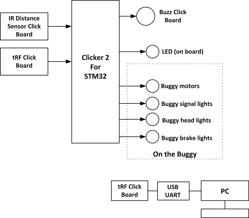
Block diagram: Fig. 22.13 shows the block diagram. The Buggy with all the components mounted on it is shown in Fig. 22.14. A number of sensor click boards, a buzzer click board, and a sound sensor module are used in the system (see www.mikroe.com for a list and details of all the click boards).
Figure 22.13Block diagram of the project.
Figure 22.14The Buggy with the components.
Details of the various sensor boards used in the project are given below.
IR distance sensor click board: This click board (Fig. 22.15) is based on the GP2Y0A60SZ0F distance measuring sensor, which comprises an integrated position-sensitive detector, an IR LED, and a signal processing circuit. The measuring range is between 10 and 150 cm, which is well suited to mobile robotic applications. The sensor on the board is not influenced by variations caused by the reflectivity of the object whose distance is measured. The board outputs an analog voltage inversely proportional to the distance of the object. Key features of this sensor board are:
• +3.3 and +5 V operation, selectable with a jumper
• +3.3 V operation by default
• 10 to 150 cm measurement range
• Analog output
• Enable pin
• mikroBUS compatible
Figure 22.15IR Distance Sensor Click Board.
Fig. 22.16 shows the typical output of the sensor when operated with +3.3 V. It is clear from this figure that the output voltage goes down from about 2 V when the distance to the object is very close, to about 0.3 V when the object is about 150 cm away from the sensor.
Figure 22.16Output response of the sensor.
This click board is used to detect the distance to an object so that the Buggy can avoid collision with the object.
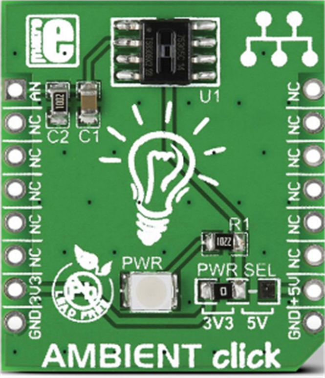
Ambient click board: This click board (Fig. 22.17) is based on the MLX75305 integrated optical sensor chip which consists of a photodiode, a transimpedance amplifier, and an output transistor. The chip converts ambient light intensity into a voltage and can operate from either +3 V or +5 V, and is configured for +3.3 V operation by default. The analog output voltage is directly proportional to the light intensity (μW/cm2) and is 0 when the sensor is dark. The voltage increases linearly as the ambient light intensity is increased. This click board is used to detect when it is dark to turn ON the head lights.
Figure 22.17Ambient Click Board.
Buzz click board: This click board (Fig. 22.18) includes a piezoelectric buzzer capable of emitting audio signals. The resonant frequency of the buzzer is 3.8 kHz. The board can operate with both +3.3 V and +5 V, where by default it is configured for +5 V operation. The board can be connected either to digital output pin or to a PWM line. Using the PWM line enables sounds at different frequencies to be generated using the mikroC Pro for ARM compiler built-in sound library. The signal frequency determines the sound pitch, while the duty cycle determines the amplitude of the sound signal. This click board is used to generate audible sound when the Buggy detects an obstacle on its way.
Figure 22.18Buzz Click Board.
Sound sensor board: The KY-038 sound sensor board was used in the project (Fig. 22.19). This board consists of an electret microphone, a comparator chip, a potentiometer, and a few resistors. The board is operated from +3.3 V power supply, obtained from the click board socket mikroBUS 3 mounted at the rear of the Buggy. The sound sensor board provides both a digital and an analog output. In this project, the digital output (D0) is used only. In digital mode, the board detects sounds, and when the sound level is above a threshold level, the output goes from logic 0 to 1 as long as the sound is present, otherwise the output is at logic 0. This click board is used to detect sound (e.g., clapping hands) and then stops the Buggy as an emergency.
Figure 22.19Sound sensor board.
Circuit diagram: There are three mikroBUS sockets on the Buggy in the form of vertical plates. As shown in Fig. 22.20, two sockets (mikroBUS 1 and mikroBUS 2) are in front of the Buggy, and one socket (mikroBUS 3) is at the rear of the Buggy. Additionally, the Clicker 2 for STM32 development board has two mikroBUS sockets mounted on it. Therefore, in total, there are five mikroBUS sockets available for the use of Clicker boards.
Figure 22.20mikroBUS sockets on the Buggy.
The click boards are connected to the mikroBUS sockets on the Buggy as follows (see Fig. 22.14):
Click board
mikroBUS socket
Place of the mikroBUS socket
IR distance sensor
mikroBUS 1
Front of the Buggy
Ambient
mikroBUS 2
Front of the Buggy
Buzz
mikroBUS 1
Clicker 2 for STM32
The Sound sensor board (KY-038) was connected as follows:
KY-038 pin
Clicker 2 for STM32 pin
GND
GND on mikroBUS 3 socket
+3.3 V
+3.3 V on mikroBUS 3 socket
D0
pin 1 (AN) on mikroBUS 3 socket
Notice that pin 1 (AN) on mikroBUS 3 socket is internally connected to port pin PC2 of the Clicker 2 for STM32 development board.
A mikroBUS socket is a 2 × 8 DIL type socket with the pin names as shown in Fig. 22.21, providing interface for SPI, I2C, analog, UART, interrupt, PWM, reset, and power supply pins. As shown in the figure, the pins of a mikroBUS socket can be numbered such that the pin at the top left position is pin 1.
Figure 22.21mikroBUS socket layout.
The interface between the click boards used in this project and the corresponding Clicker 2 for STM32 pin names is as follows (see the Buggy user manual at:
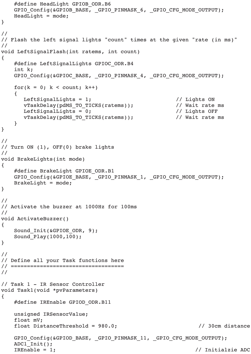
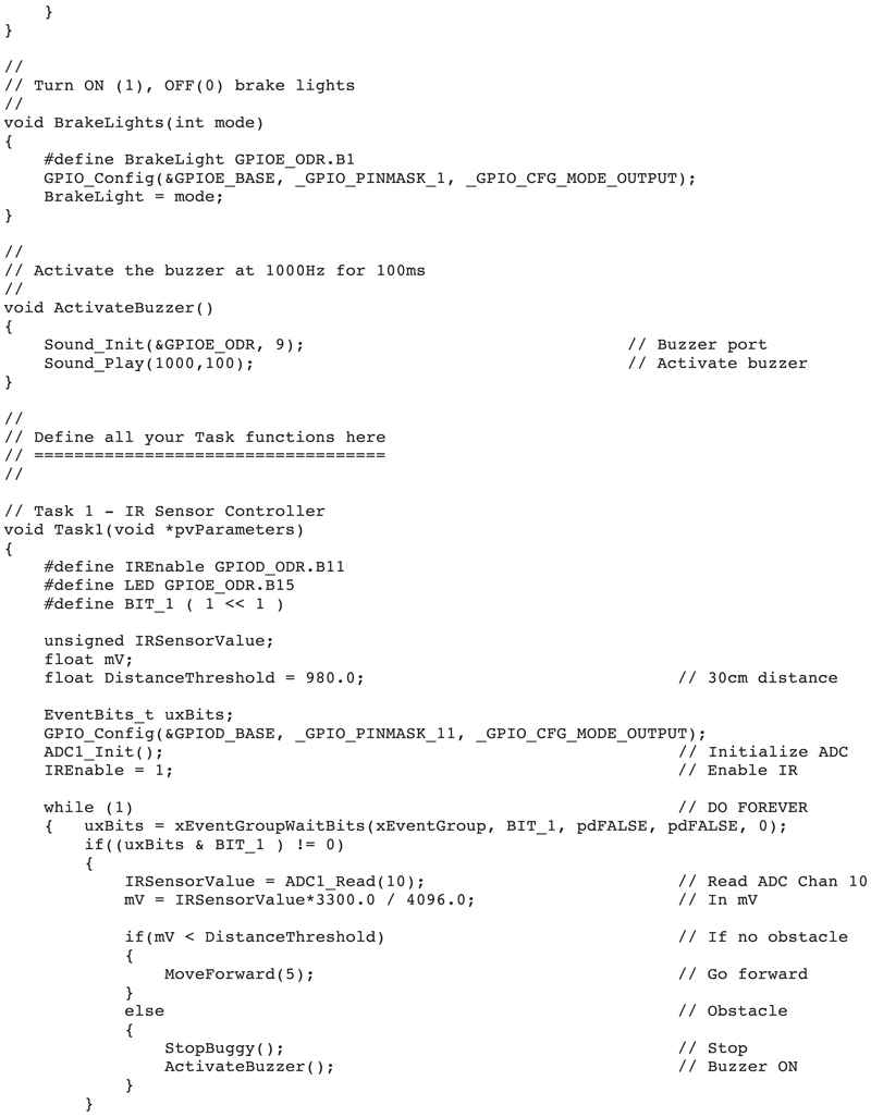
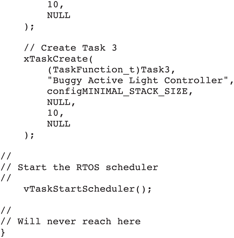
Program listing: Fig. 22.22 shows the program listing (program: obstacle.c). The program consists of four tasks excluding the Idle task. The operation of each task is described below:
Figure 22.22obstacle.c program listing.
Task 1 (IR sensor controller)
Define the IR Distance Threshold
Initialize the ADC
DO FOREVER
Read distance to obstacle
IF distance to obstacle < IR Distance Threshold THEN
Move Forward
ELSE
Stop the Buggy
Turn ON Brake lights
Activate buzzer
Flash the left signal lights
Turn OFF Brake lights
Turn left
ENDIF
ENDDO
Task 2 (head lights controller)
Define the Dark Threshold
Initialize the ADC
DO FOREVER
Read light level
IF light level < Dark Threshold THEN
Turn ON the head lights
ELSE
Turn OFF the head lights
ENDIF
ENDDO
Task 3 (active light controller)
DO FOREVER
Turn ON on-board LED at port PE12
Wait 200 ms
Turn OFF on-board LED at port PE12
Wait 200 ms
ENDDO
Task 4 (emergency stop controller)
DO FOREVER
IF ambient sound detected THEN
Stop the Buggy
Turn OFF the head lights
Turn OFF the Brake lights
Suspend the scheduler
ENDIF
ENDDO
The analog output of the IR distance sensor board is connected to port pin PC0, which corresponds to channel 10 of the ADC on the development board. It was determined by experimentation that when the distance in-front of the Buggy is about 30 cm, then the value returned by the IR Distance Sensor Click board was about 980 mV. This value was, therefore, used to determine when an object was in-front of the Buggy. If the returned value is less than 980 mV, then it is assumed that the obstacle is about 30 cm away from the Buggy. When this happens, the Buggy is stopped to avoid collision with the obstacle. The brake lights are turned ON, the buzzer is activated for a short time and the left signal lights are flashed 3 times. Then, the brake lights are turned OFF and the Buggy makes a 90-degree left turn with the hope to avoid the obstacle. The Buggy then moves forward if there are no more obstacles within 30 cm. The speed of the Buggy is set to 1/5th of its full-scale value to make the Buggy move slowly. Notice that because there are no encoders on the wheel motors, it is not possible to turn the Buggy exactly by 90 degrees. The functions to control the motors and lights are similar to the ones given in the previous project. The buzzer is activated using the built-in Sound Library (this library must be enabled in the Library Manager before the program is compiled) where a 1-kHz signal is sent to the buzzer for the duration of 100 ms.
The analog output of the Ambient Click is connected to port pin PC1 which corresponds to channel 11 of the ADC on the development board. This board measures the ambient light level in-front of the Buggy. It was determined by experimentation that the value of about 105 mV corresponds to a dark level threshold below which the head lights of the Buggy are turned ON, and above this value the head lights are turned OFF using the following code:
while(1)
{
AmbientSensorValue = ADC1_Read(11);
mV = AmbientSensorValue*3300.0 / 4096.0;
if(mV < DarkThreshold)
HeadLights(1);
else
HeadLights(0);
}
The on-board LED connected to port pin PE12 of the development board flashes rapidly (every 200 ms) to indicate that the Buggy is active.
The Buggy can be stopped on emergency by clapping hands near the microphone of the sound sensor board. The potentiometer of this sensor board should be adjusted carefully so that the output of the board is normally at logic 0 when the Buggy is operating. The output should go to logic 1 when hands are clapped close to the sound sensor. When the output of the sound sensor board goes to logic 1, the wheel motors are stopped, head lights and the brake lights are turned OFF (if they are ON), and finally the FreeRTOS scheduler is suspended so that all the tasks stop.
22.8. Project 60: controlling the Buggy remotely
Description: In the previous project, we have learned how to control the Buggy in a multitasking environment and developed an obstacle avoiding mobile robot using the Buggy together with a number of sensors. In this project, we will be controlling the Buggy remotely using radiofrequency (RF) transmitter and receiver modules. An RF receiver module is mounted on the Buggy which receives commands from an RF transmitter module interfaced to a PC via the USB socket. In addition, an IR distance sensor click board is mounted in-front of the Buggy and a Buzz click board is plugged-in to mikroBUS 1 socket on the development board as in the previous project. The movements, signal lights, head lights, and brake lights of the Buggy are controlled by sending commands from the PC. The following are the valid commands:
F:
go forward
L:
turn left
R:
turn right
S:
stop
H:
turn ON the head lights
h:
turn OFF the head lights
B:
turn ON the brake lights
b:
turn OFF the brake lights
P:
flash the left signal lights 3 times
Q:
flash the right signal lights 3 times
Command F moves the Buggy forward at a reduced speed. As in the previous project, if there is an obstacle in-front of the Buggy as it is moving forward, then it stops and activates the buzzer for a short time. Commands L and R turn the Buggy left and right, respectively. Since there are no encoders on the wheel motors, it is not possible to turn exactly by 90 degrees. Command S stops the Buggy. Commands H and h turn ON and OFF the head lights, respectively. Similarly, commands B and b turn ON and OFF the brake lights, respectively. Commands P and Q flash the left and the right signal lights 3 times, respectively, at a rate of 100 ms.
Block diagram: Fig. 22.23 shows the block diagram of the project. The Buggy with all the components mounted on it is shown in Fig. 22.24. The IR distance sensor click board and the Buzz click board were used in the previous project and their details are not repeated again.
Figure 22.23Block diagram of the project.
Figure 22.24The Buggy with the components.
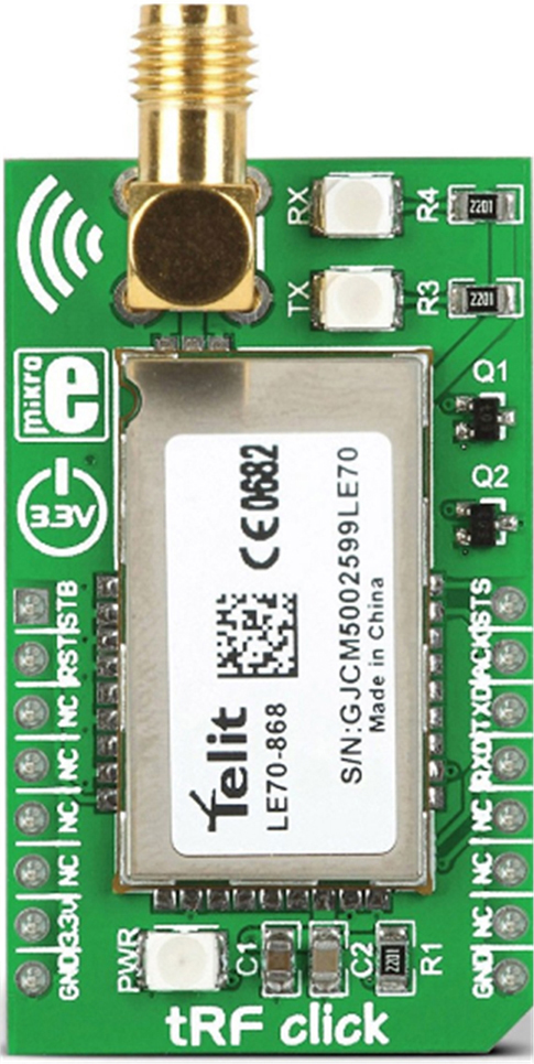
Communication between the PC and the Buggy is via a pair of RF transmitter/receiver modules known as the tRF click boards. tRF click board (Fig. 22.25) is based on the LE70-868 RF module from Telit. tRF click is a complete short-range RF communication solution, operating in the 868 MHz ISM license-free frequency band. It features the complete RF, software stack, and packet handling onboard, exposing just a simple UART interface, offering familiar Hayes AT command set. It can be used in PTP (Point to Point) or Star topology wireless networks, using the Telit proprietary protocol. This module is also capable operating as the smart repeater, greatly improving the network range.
Figure 22.25tRF Click board.
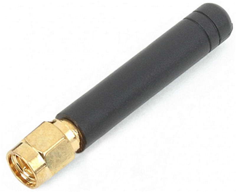
tRF includes both an RF transmitter and a receiver, and it is interfaced to a host computer through its UART ports. The operating voltage of the device is +3.3 V. A suitable 868-MHz antenna must be connected to the device before it is used (Fig. 22.26). tRF has an output power of 500 mW, which is within the acceptable license limits. Manufacturer’s data sheet quotes that the device has a range of around 10 km in PTP applications, where the transmitter and the receiver antennas are in sight of each other (the range can be increased by directional antennas).
Figure 22.26tRF antenna (a 90-degree antenna is also available).
Circuit diagram: The click boards are connected to the mikroBUS sockets on the Buggy as follows (see Fig. 22.24):
Click board
mikroBUS socket
Place of the mikroBUS socket
IR distance sensor
mikroBUS 1
Front of the Buggy
Buzz
mikroBUS 1
Clicker 2 for STM32
tRF click
mikroBUS 2
Clicker 2 for STM32
When connected to mikroBUS 2 socket on the development board, the tRF UART pins are by default connected to UART pins PD8 and PD9 of the development board. The interface between the click boards used in this project and the corresponding Clicker 2 for STM32 pin names is as follows (see the Buggy user manual at:
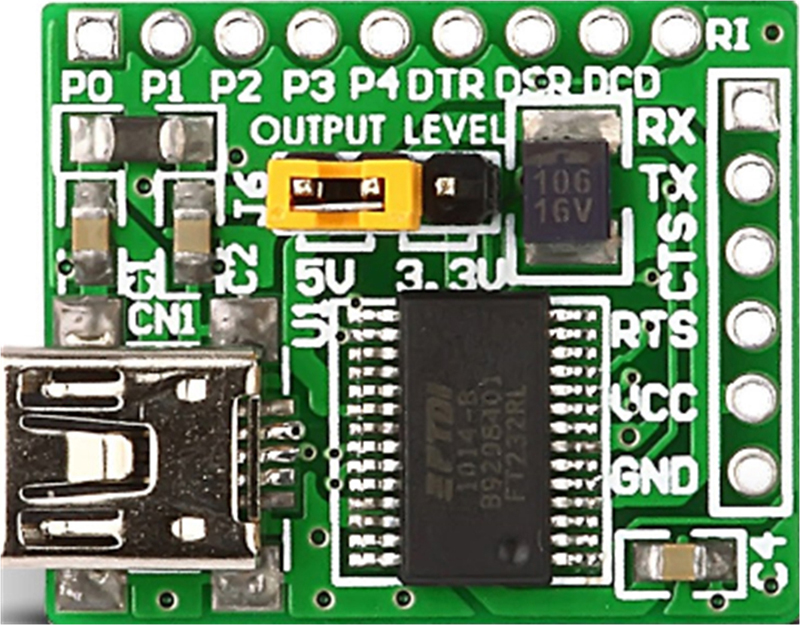
The Buggy communicates with the PC wirelessly by connecting a tRF click board to the PC via the USB port of the PC. A USB UART board is used to interface the PC to the tRF click board. UAB UART board (Fig. 22.27) consists of a mini USB socket, a UART chip, and a jumper used to select the output voltage between +3.3 and +5 V. Because the tRF click board operates at +3.3 V, the jumper on the USB UART board must be set to +3.3 V (see Fig. 22.27).
Figure 22.27USB UART board.
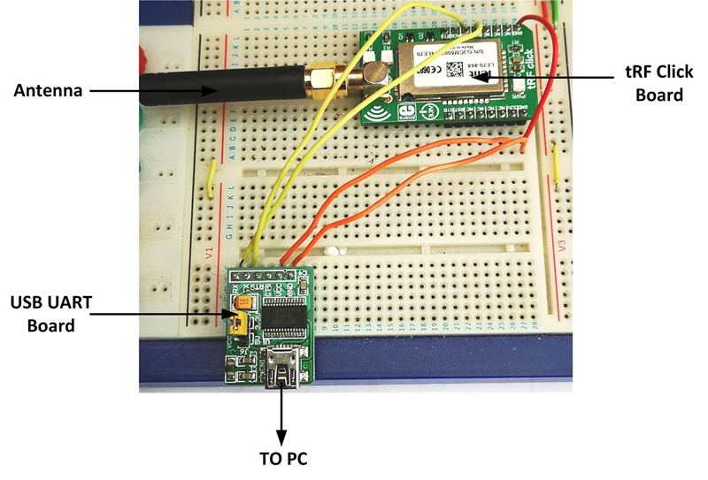
The connections between the USB UART board and the tRF click board are as follows (see Fig. 22.28):
USB UART board
tRF click board
VCC
+3.3 V
GND
GND
TX
TXD
RX
RXD
Figure 22.28Connecting USB UART board to tRF click board.
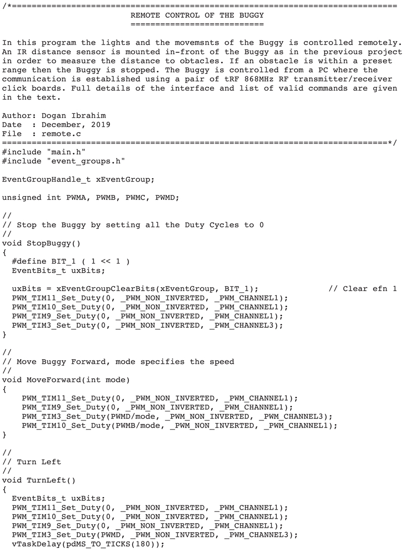
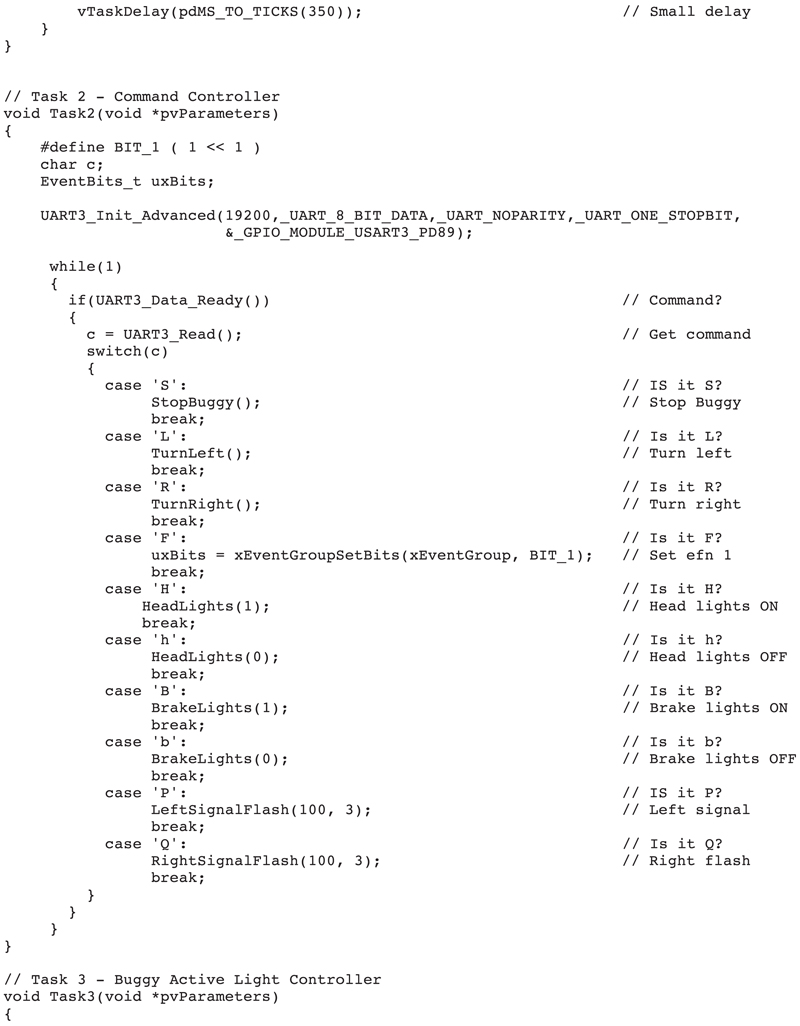
Program listing: Fig. 22.29 shows the complete program listing (program: remote.c). The program consists of three tasks in addition to the Idle task. The tasks perform the following operations:
Figure 22.29remote.c program listing.
Task 1 (IR distance sensor click)
Define distance threshold
Initialize ADC
Enable IR distance sensor click
DO FOREVER
Check event flag 1
IF event flag 1 is set THEN
Read distance to obstacle
IF distance to obstacle < distance threshold THEN
Move forward
ELSE
Stop Buggy
Activate buzzer
ENDIF
ENDIF
ENDDO
Task 2 (command controller)
Set tRF port baud rate to 19200
DO FOREVER
IF a command is entered THEN
IF command is S THEN
Stop the Buggy
ELSE IF command is L THEN
Turn left
ELSE IF command is R THEN
Turn right
ELSE IF command is F THEN
Set vent flag 1
ELSE IF command is H THEN
Turn head lights ON
ELSE IF command is h THEN
Turn head lights OFF
ELSE IF command is B THEN
Turn brake lights ON
ELSE IF command is b THEN
Turn brake lights OFF
ELSE IF command is P THEN
Flash left signal light 3 times
ELSE IF command is Q THEN
Flash right signal light 3 times
ENDIF
ENDIF
ENDDO
Task 3 (active light controller)
Turn the on-board LED ON
Wait 200 ms
Turn the on-board LED OFF
Wait 200 ms
When a command is entered at the PC keyboard, this command is transmitted to the tRF module mounted on the Buggy which is then read by the UART of the Clicker 2 for STM32 development board. Commands are received using the standard UART data receive commands. Command F sets event flag 1 which then enables Task 1 to call function MoveForward to move the Buggy forward. If the Buggy detects an obstacle in-front of it within the pre-specified distance, then it stops and activates the buzzer for a short time. Event flag 1 is cleared when the Buggy stops. Commands L and R turn the Buggy left and right respectively. The Buggy can be turned wither after it is stopped, or while it is moving forward. Event flag 1 is set inside the left and right turn functions so that the Buggy starts moving if it was stopped either by the S command or after encountering an obstacle.
Testing the program: The steps to test the program are given below:
• Compile the program and upload it to the development board
• Connect a USB cable between the PC USB port and the USB UART board (see Fig. 22.28)
• Start a terminal emulation program on the PC (e.g., Hyperterm or Putty) and set the baud rate to 19200 (default baud rate of the tRF module)
• Put the Buggy on the floor
• Enter command H on the PC keyboard. The head lights should come ON. Entering command h should turn OFF the head lights
• Enter commands B and b to turn the brake lights ON or OFF, respectively
• Test the signal lights by entering commands P and Q
• Enter command F on the PC keyboard. The Buggy should start moving forward and it will stop when an obstacle is within the pre-specified threshold distance from the Buggy.
• Turn L or R to turn the Buggy as required
• Test the S command to make sure that the Buggy stops when this command is entered