This chapter describes a car park management system where the idea is to control the operation of an imaginary car park using the FreeRTOS application program interface (API) functions. It is assumed that the car park has only one level. An LCD display close to the car park shows the number of free spaces available in the car park. Members of the car park are allowed to use the car park where each member is given an RFID (Radio Frequency IDentification) card for identification. A barrier is placed at the entrance to the car park, which is lifted up with a stepper motor. If there are spaces in the car park and when a member customer places an authorized RFID card close to the card reader near the entrance to the car park, then the barrier lifts up to let the car enter the car park. This chapter describes the design and programming of the car park system.
Keywords:
Clicker 2 for STM32
FreeRTOS
mikroC Pro or ARM
car park
car cark controller
stepper motor
pressure switch
RFID tag
RFID reader
RDM6300
20.1. Overview
In the previous chapters, we have covered most features and application program interface (API) functions of the FreeRTOS kernel. We have also developed many simple projects to show how different functions and features can be used in practical applications.
In this chapter, we develop a more complex multitasking project as a car park management system, using several sensors and a servo motor in a multitasking environment with the FreeRTOS kernel and the Clicker 2 for STM32 microcontroller development board.
20.2. Project 55: car park control
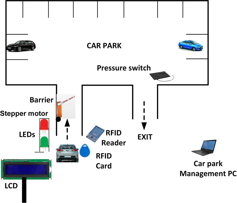
Description: This is a car park management system where the idea is to control the operation of a car park. It is assumed that the car park has one level with a capacity of 100 cars. An LCD display close to the car park shows the number of free spaces available in the car park. Only members of the car park are allowed to use the car park where each member is given an RFID (Radio Frequency IDentification) card for identification. A barrier is placed at the entrance to the car park that is operated (i.e., lifted up) with a stepper motor. If there are spaces in the car park and when a member customer places an authorized RFID card close to the card reader near the entrance to the car park, then the barrier is lifted up automatically to let the driver into the car park. Unauthorized RFID cards are rejected and the barrier is not lifted up. There is no barrier at the exit from the car park, but a passive pressure switch is placed under the exit route that detects the vehicles as they leave the car park. The number of spaces available inside the car park is calculated as the cars enter and leave the car park and this is displayed on the LCD continuously. The barrier is not lifted up if there are no spaces inside the car park. A Red and a Green light (e.g., LED in this project) are mounted at the entrance to the car park. When the Red LED is ON, the driver is required to wait until the Green LED comes ON. The Green LED comes ON when the barrier is lifted up so that a car can enter the car park. When the barrier is down, the Red LED comes ON and the Green LED is turned OFF. The car park is managed from a PC, where the person in charge can set the capacity of the car park. Although the default capacity is 100, this can be changed from the keyboard, for example, when part of the car park is not available for parking. All of the operations of the car park are controlled using a Clicker 2 for STM32 microcontroller development board together with the mikroC Pro for ARM compiler and FreeRTOS kernel as in the previous projects in this book.
Aim: The aim of this project is to show how some of the FreeRTOS API functions we have covered in the earlier chapters can be used in a practical application.
Block diagram: Fig. 20.1 shows the block diagram of the car park. Interface to the microcontroller development board is not shown in this figure.
Figure 20.1Block diagram of the car park.
The stepper motor
Stepper motors are rotary actuators that allow for precise control of the angular position of an object connected to the shaft of the motor. As was described in Chapter 14, stepper motors can be driven by several ways, such as using bipolar transistors, MOSFET transistors, or integrated circuits such as L293, ULN2003, and so on. In this project, the 28BYJ-48 unipolar stepper motor is used (see Fig. 14.29) with the ULN2003 IC-based motor driver module (see Fig. 14.30) to control the barrier at the entry to the car park. The stepper motor rotates anticlockwise by 90 degrees to lift the barrier up to let a car into the car park. Similarly, it is rotated by 90 degrees clockwise to close the barrier after the vehicle is entered the car park.
The pressure switch
A pressure switch is placed under the road in the path of the exit route that detects when a car is leaving the car park. The state of this switch is at logic 0 and goes to logic 1 when a car is over the switch. This is detected by the system and is used in calculating the available free spaces in the car park.
The RFID reader
RFID systems consists of RFID devices (or readers) and RFID tags (or cards). RFID devices use electromagnetic fields to automatically identify and track compatible RFID tags. The tags contain unique electronically stored information, which is read by the RFID readers. RFID tags are used in many industries and commonly in security applications. For example, the reader-tag pairs can be used to unlock doors, they can be attached to possessions or implanted in animals and people so that they can be tracked. RFIDs are similar to barcodes used in supermarkets to identify products, but unlike the barcodes, the tags do not need to be within the line of sight of the readers. Additionally, tags can contain much more information than the simple barcodes.
RFID tags can be either passive or active (battery operated). Passive tags are cheaper and smaller and are used more commonly. Passive tags must be placed very close to the RFID readers (e.g., at 5 cm) so that their contents can be read. These tags can be read-only or read-write type. Read-only tags are pre-programmed in factory with unique numbers and these numbers can be read using compatible RFID readers. Active RFID tags have the advantages, in that they can be read from longer distances, but they are much more expensive than the passive tags.
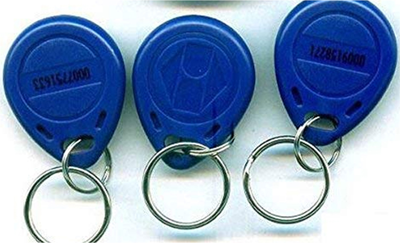
In this project, a passive RFID tag system is used. The RFID reader used in this project is the RDM6300 type UART-based reader (see Fig. 20.2). This reader is EM4100 protocol compatible and operates with the 125-kHz RFID tags (see Fig. 20.3). The basic features of the RDM6300 readers are as follows:
• Operating frequency: 25 kHz
• Working voltage: +5 V
• Current consumption: <50 mA
• Receive distance: <5cm
• Working temperature: −10°C to +70°C
Figure 20.2RDM6300 RFID reader.
Figure 20.3125-kHz RFID tags.
The RDM6300 is sold with a coil antenna that communicates with the RFID cards. This antenna must be connected to the reader board. Fig. 20.4 shows the pin configuration of the RDM6300 reader.
Figure 20.4RDM6300 pin configuration.
There are three headers on the board with the following functions. Notice that Header 3 is for testing where an optional external LED can be connected to this header. The LED goes from logic HIGH to LOW when an RFID tag is present:
Header P1
Pin number
Description
1
TX (UART transmit)
2
RX (UART receive)
3
Not used
4
GND
5
+5 V power supply
Header P2
1 Antenna
2 Antenna
Header 3
1 External LED
2 +5 V power supply
3 GND
The RDM6300 reader operates at 9600 Baud, eight data bits, one stop bit, and no parity bit. At 9600 baud, the bit time is 104 μs. The interface protocols available for this reader are the Weigang26 and TTL level RS232. In this project, the TTL level RS232 interface and protocol is used. Normally, the standard RS232 signal voltage levels are ±12 V. TTL-based RS232 signal voltage levels are 0 or +5 V (or 0 to +3.3 V) where the line is normally at +5 V and goes to 0 V at the beginning of data transmission (i.e., the start bit is at logic 0 V). The reader output consists of 14 bytes as follows:
• 1 byte start flag (0 × 02)
• 10 ASCII data characters
• 2 byte checksum
• 1 byte end flag (0 × 03)
The start and end flags are always 0 × 02 and 0 × 03, respectively. The checksum is calculated by exclusive Or’ing all the data bytes.
Notice that the card numbers marked on the RFID cards is a 10-digit decimal number. For example, if the decimal number on the card is 007564912, this corresponds to hexadecimal number 00736E70.
Circuit diagram: The circuit diagram of the project is shown in Fig. 20.5. The LCD is connected to the Clicker 2 for STM32 development board as in the previous projects using LCDs. The stepper motor is attached to the motor driver board and the board pins IN1, IN2, IN3, and IN4 are connected to port pins PC0, PC1, PC2, and PC3, respectively. The motor driver board is powered from an external +5 V power supply. The pressure switch is connected to port pin PA4. The output of this switch is at logic 0 and goes to logic 1 when a car is present on the switch. The RFID reader module is connected to UART pins PD5 (TX) and PD6 (RX). Power to the RFID reader module is supplied from the development board. The two LEDs on the development board are used: LED at port pin PE12 is assumed to be the Red LED, and the LED at port pin PE15 is assumed to be the Green LED.
Figure 20.5Circuit diagram of the project.
The interface between the development board and the various peripheral devices is summarized as follows:
External device
Clicker 2 for STM32 pin
Pressure switch
PA4
RFID reader
PD5 (TX), PD6 (RX)
Stepper motor
PC0, PC1, PC2, PC3
Red LED
PE12
Green LED
PE15
LCD
PE7, PE8, PE9, PC10, PC11, PC12
USB UART Click board
mikroBUS 2
The antenna of the RFID reader module is connected to header pins P2. The LED interface of the RFID reader module is not used in this project.
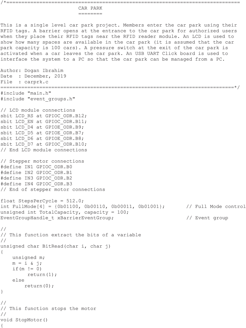
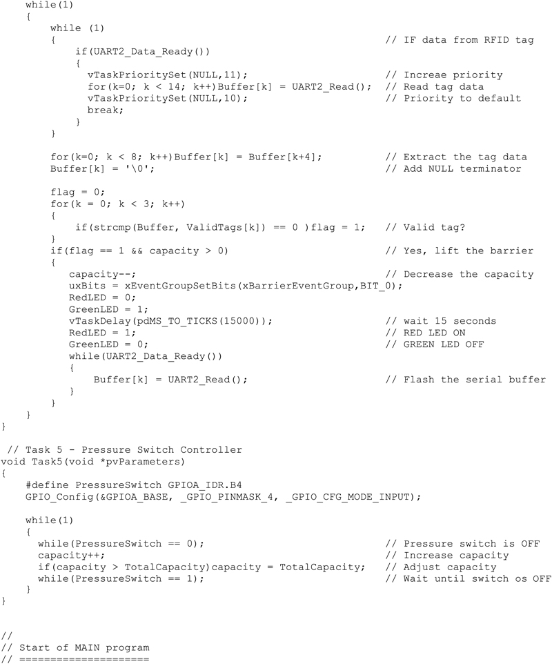
Program listing: Fig. 20.6 shows the program listing (program: carprk.c). The program consists of five tasks in addition to the Idle task. The tasks are:
TASK1: Stepper motor controller
TASK2: LCD controller
TASK3: UART controller
TASK4: RFID controller
TASK5: Pressure switch controller
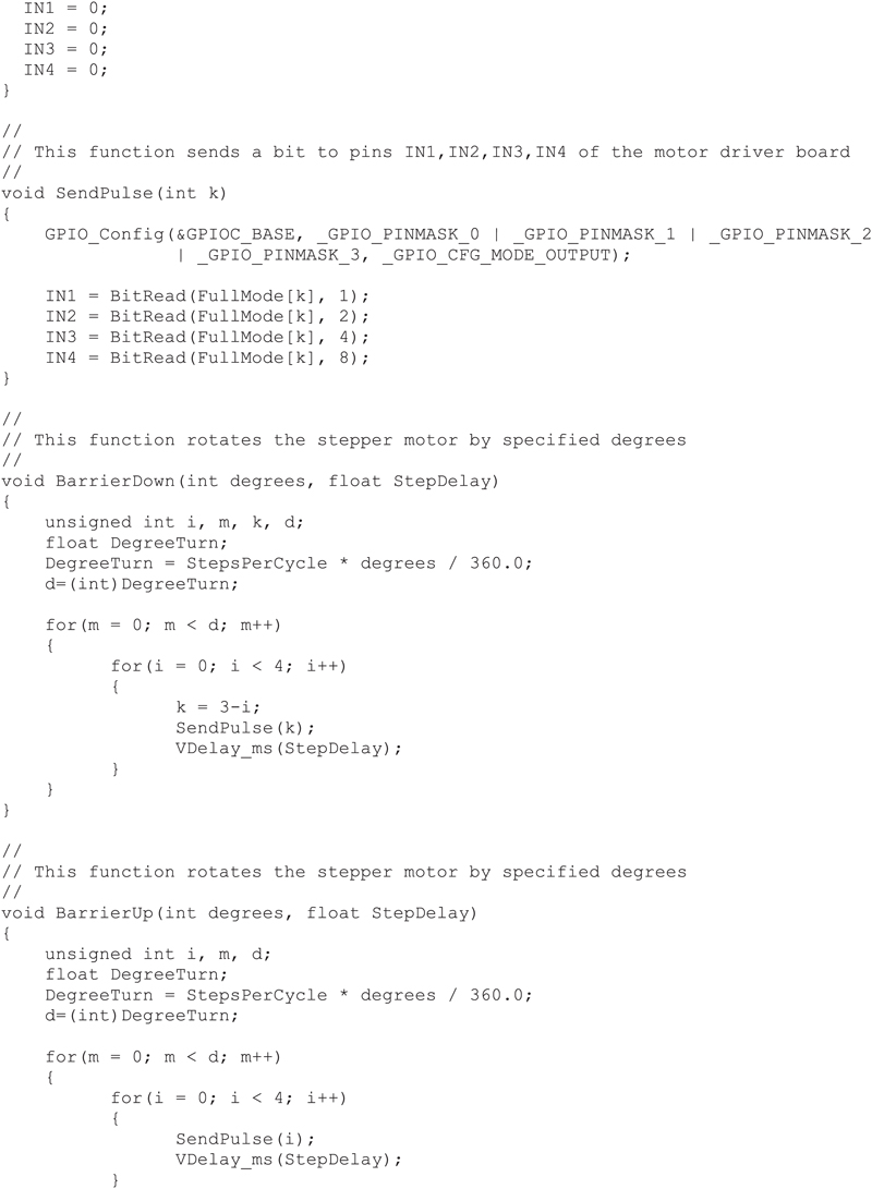
Figure 20.6carprk.c program listing.
The operation of each task is described using PDL statements:
TASK1 (stepper motor controller)
DO FOREVER
Wait for event flag 0 to be set
Increase task priority
Lift up the barrier
Task priority back to default
Wait for 10 seconds for a car to enter
Increase task priority
Lower the barrier
Task priority back to default
ENDDO
TASK2 (LCD controller)
Initialize the LCD
Display heading “Free Spaces:” at row 1
DO FOREVER
Display free spaces at row 2
ENDDO
TASK3 (UART controller)
Set the UART baud rate
DO FOREVER
Display heading “CAR PARK MANAGEMENT SYSTEM”
Display “Enter the Car Park Capacity:”
Read the car park capacity
ENDDO
TASK4 (RFID controller)
Set the UART baud rate
Turn ON Red LED
Turn OFF Green LED
DO FOREVER
Read RFID tag number
IF this is a valid tag and there are free spaces in the car park THEN
Decrement free space count by one
Turn ON Green LED
Turn OFF Red LED
Set event flag 0 so that the barrier is lifted up
Wait 15 seconds for the barrier
Turn OFF Green LED
Turn ON Red LED
ENDIF
ENDDO
TASK5 (pressure switch controller)
DO FOREVER
IF a car is present on the switch THEN
Increment free space count by one
Wait until the car is not on the switch
ENDIF
ENDDO
A typical operation cycle of the car park is as follows:
On entry:
• Car park capacity is displayed on the LCD.
• Red LED is ON, Green LED is OFF.
• A car approaches the car park.
• Member places the RFID tag close to the tag reader.
• The card is accepted.
• Car park free space count is decremented by 1.
• Barrier is lifted up.
• Green LED is ON, Red Led is OFF.
• Car enters the car park.
On exit:
• Car is on the pressure switch at the exit.
• Increment the free space count by 1.
• Wait until the car leaves.
Management:
• Car park manger is prompted to enter the car park capacity.
• New car park capacity is accepted.
At the beginning of the program, the interface between the LCD and the development board is defined. Also, the interface between the stepper motor and the development board is defined. The program then defines some of the variables, such as the StepsPerCycle, FullMode, and default capacity.
The motor RPM is set to 10 in Task 1. This task waits until event flag 0 is set. When this flag is set, function BarrierUP is called to lift the barrier up. The stepper motor is requested to turn by 90 degrees anticlockwise to open the barrier. This is done after the priority of the task is increased so that the task cannot be interrupted by other tasks in the system. A complete turn of the stepper motor requires StepsPerCycle steps, where each step consists of 4 pulses. Since a complete turn is 360 degrees, 90 degrees of rotation is achieved by sending DegreeTurn steps to the motor where:
DegreeTurn=StepsPerCycle×degrees360.0
After the barrier is lifted up, the task priority is lowered to its default value and the task waits for 10 seconds so that the car is entered the car park. The priority of the task is increased again, and the barrier is lowered.
The LCD controller task gets the free space count from variable capacity and then displays the free spaces in the second row of the LCD.
New capacity is entered through the PC keyboard. UART3 of the development board is used to interface to the PC. As soon as the capacity is changed, the new capacity is displayed on the LCD. Notice that variable capacity is the number of free spaces at any time and variable TotalCapacity is the actual capacity of the car park.
In this program, three valid RFID tags are used for demonstration purposes. Notice that the card reader returns 14 bytes, but only the bytes that represent the number on the cards are extracted and used in the program. These valid tags had the following identities:
Number on the tag
Number returned by the tag reader
0014913318
00E38F26
0007564912
00736E70
0007576514
00739BC2
The valid tags are stored in a two-dimensional character array called ValidTags:
UART2 of the development board is interfaced to the RFID tag reader. If a character is available at the UART buffer, then the priority of Task 4 is increased so that the UART is not interrupted by other tasks, and the tag data are read and stored in character array called Buffer. The priority is then lowered back to its default value. The tag number is then checked against the valid tags:
flag = 0;
for(k = 0; k < 3; k++)
{
if(strcmp(Buffer, ValidTags[k]) == 0)flag = 1;
}
Variable flag is set to 1 if the tag read is a valid tag. Event flag 0 is then set if the car park has free spaces available. Red LED is turned OFF and Green LED is turned ON so that the car is given permission to enter the car park.
The output state of the pressure switch is at logic 0. When a car is present on this switch, the switch state goes to logic 1. This change of state is detected by the program and the free space count is increased by 1 as a car is leaving the car park.
Fig. 20.7 shows an example display on the PC screen prompting the user to enter the car park capacity.
Figure 20.7Display on the PC screen.
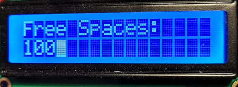
The LCD displays the free space available at the cark park and an example display is shown in Fig. 20.8.