The term microcomputer is used to describe a system that includes a minimum of a microprocessor, program memory, data memory, and input-output (I/O). Some microcomputer systems include additional components such as timers, counters, analog-to-digital converters, and so on. Thus, a microcomputer system can be anything from a large computer having hard disks, floppy disks, and printers, to a single chip embedded controller. This chapter is an introduction to microcontrollers and it describes the basic differences between the microprocessors and microcontrollers. Additionally, the chapter describes briefly the various components of a microcontroller, such as the types of memories used, input-output, timers, interrupts, ADC and DAC, Wi-Fi, Ethernet, and so on. The differences between the Von Neumann and Harvard architectures are explained. Finally, the important topic of RISC (reduced instruction set computer) and CISC (complex instruction computer) is explained briefly.
Keywords
microcontroller
microprocessor
microcontroller components
Von Neumann architecture
Harvard architecture
RISC machine
CISC machine
1.1. Overview
The term microcomputer is used to describe a digital processing system that includes a minimum of a microprocessor, program memory, data memory, and input-output (I/O). Some microcomputer systems include additional components such as timers, counters, analog-to-digital converters, and so on. Thus, a microcomputer system can be anything from a large computer having hard disks, optical disks, SSD drives, printers, and plotters to a single chip embedded controller.
In this book we are going to consider only the type of microcomputers that consists of a single silicon chip. Such microcomputer systems are also called microcontrollers and they are used in many household goods such as microwave ovens, TV remote control units, cookers, hi-fi equipment, CD players, personal computers, fridges, games consoles, etc. There are a large variety of microcontrollers available in the market place, ranging from 8-bits to 32-bits or even 64-bits. In this book we shall be looking at the programming and system design using a member of the 32-bit STM32 family of microcontrollers, manufactured by the STMicroelectronics. As we shall be seeing in the next chapter, STM32 family is based on the highly popular ARM processor architecture. In this chapter we shall be looking at the features of the microcontroller systems and describe their basic building blocks.
1.2. Microcontroller systems
A microcontroller is a single-chip computer. Micro suggests that the device is small, and controller suggests that the device can be used in control applications. Another term used for microcontrollers is embedded controller, since most of the microcontrollers are built into (or embedded in) the devices they control.
A microprocessor differs from a microcontroller (or a microcomputer) in many ways. The main difference is that a microprocessor requires several other components for its operation, such as program memory and data memory, input-output devices, clock circuit, interrupt circuits, etc. A microcontroller, on the other hand, has all the support chips incorporated inside the same chip. All microprocessors and microcontrollers operate on a set of instructions (or the user program) stored in their program memories. A microcontroller fetches the instructions from its program memory one by one, decodes these instructions, and then carries out the required operations.
Microprocessors and microcontrollers have traditionally been programmed using the assembly language of the target device. Although the assembly language is fast and results in less memory usage, it has several major disadvantages. An assembly program consists of mnemonics and it is difficult to learn and maintain a program written using the assembly language. Also, microcontrollers manufactured by different firms have different assembly languages and the user is required to learn a new language every time a new microcontroller is to be used for a project. Microcontrollers can also be programmed using a high-level language, such as BASIC, PASCAL, C, etc. High-level languages offer many advantages: it is much easier to learn a high-level language than an assembler language. Also, very large and complex programs can easily be developed using a high-level language. It is much easier to maintain a program written using a high-level language. Programs written using a high-level language can easily be ported to run on different microcontrollers with simple or no modifications to the source codes. In this book we shall be learning the programming of STM32 family of microcontrollers using the popular mikroC Pro for ARM language and the IDE (integrated development environment), developed by mikroElektronika (www.mikroe.com).
In most microcontroller-based applications, a microcontroller is used for a single task, such as controlling a motor, controlling the temperature, humidity or the pressure, turning an LED ON or OFF, responding to external switches, and so on. In this book we are interested in using a microcontroller in real time as well as in multitasking applications. A real-time application differs from a normal application as it requires a very quick response from a microcontroller. For example, in a position control application it may be required to stop a motor as soon as an input condition changes. Or, in digital signal processing applications the processor is required to respond to input signal changes very quickly. In multitasking applications, there could be several interrelated tasks running on a single microcontroller such that the CPU time and the microcontroller resources are shared between these tasks. A scheduler runs in the background and it makes sure that the tasks run correctly and share the CPU as required by the application. In this book, the highly popular FreeRTOS real-time multitasking kernel is used in the projects. The book describes the operation of the FreeRTOS and gives example projects to show how the various functions supported by the FreeRTOS kernel can be used in practical applications. Many tested and working projects are given in later chapters of the book.
In general, a single chip is all that is required to have a running microcontroller system. In practical applications, however, several additional external components may be required to allow a microcomputer to be interfaced with its environment. The resulting system is then usually called a microcontroller development kit (or microcontroller development board). Microcontroller development kits simplify the tasks of developing programs greatly, since the required project is developed using the hardware kit that has already been tested by the manufacturers.
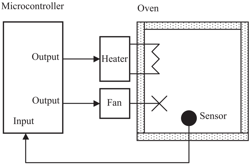
Basically, a microcontroller executes a user program which is loaded in its program memory. Under the control of this program, data is received from external devices (inputs), manipulated, and then sent to external devices (outputs). For example, in a microcontroller-based oven temperature control system, the temperature is read by the microcomputer using an external temperature sensor. The microcomputer then operates a heater or a fan to control and keep the temperature at the required set value. Fig. 1.1 shows the block diagram of our simple oven temperature control system.
Figure 1.1Microcontroller-based oven temperature control system.
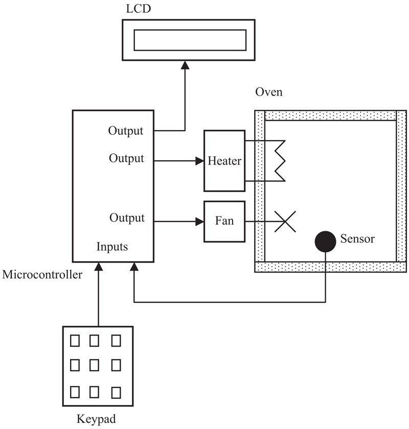
The system shown in Fig. 1.1 is a very simplified temperature control system where the microcontroller software runs in an endless loop and its only task is to control the temperature of the oven. In such a simple system the set point temperature is usually preset in the software and cannot be changed while the program is running. This is an example of a system having only one task. In a more sophisticated system we may have a keypad to set the temperature externally while the program is running, and additionally an LCD to display the current temperature and the set point temperature. Fig. 1.2 shows the block diagram of such a more sophisticated temperature control system. The system shown in Fig. 1.2 is a multitasking system where there are more than one task running on the same microcontroller and sharing the CPU and the system resources. Here, one of the tasks is controlling the temperature, while at the same time the other task responds to the keypad entries.
Figure 1.2Temperature control system with a keypad and LCD.
We can make our design even more sophisticated (see Fig. 1.3) by adding an audible alarm to inform us if the temperature is outside the required set point value. Also, the temperature readings can be sent to a PC every second for archiving and further processing. For example, a graph of the daily temperature changes can be plotted on the PC. The system can be made even more complex and more sophisticated as shown in Fig. 1.4 if we add Wi-Fi capability so that the temperature can be monitored and controlled remotely from anywhere on the Earth. As you can see, because the microcontrollers are programmable, it is very easy to make the final system as simple or as complicated as we like. It is obvious from this simple example that as the system becomes more complex, it becomes necessary to divide the system into several interrelated tasks and then use a multitasking kernel to achieve the required control and synchronization between these tasks.
Figure 1.3More sophisticated temperature controller.
Figure 1.4Temperature control system with Wi-Fi capability.
Microcontrollers are classified by the number of bits they process. Although the 8-bit microcontrollers have been very popular in the past, the 32-bit microcontrollers, such as the STM32 family are becoming very popular, especially in complex applications that may require high speed, precision, large amounts of data and program memories, and many other resources.
The simplest microcontroller architecture consists of a microprocessor, memory, and input-output. The microprocessor consists of a central processing unit (CPU), and the control unit (CU). The CPU is the brain of the microcontroller and this is where all of the arithmetic and logic operations are performed. The control unit controls all the internal operations of the microprocessor and sends out control signals to other parts of the microcontroller to carry out the required instructions. For example, in a simple addition operation, the control unit fetches data from the memory and loads into the arithmetic and logic unit for the addition to be performed. The result is then sent back to the memory under the control of the CU.
Memory is an important part of all microcontroller systems. Depending upon the type used, we can classify memories into two groups: program memory, and data memory. Program memory stores the program written by the programmer and this memory is usually nonvolatile, that is, data is not lost after the removal of power. Data memory is where the temporary data used in a program are stored and this memory is usually volatile, that is, data is lost after the removal of power.
There are basically six types of memories as summarized below.
1.2.1. RAM
RAM means random access memory. It is a general-purpose memory which usually stores the user data in a program. RAM memory is volatile in the sense that it cannot retain data in the absence of power, that is, data is lost after the removal of power. Most microcontrollers have some amount of internal RAM. Several megabytes are a common amount, although some microcontrollers have more, some less. In some microcontrollers it may be possible to extend the available RAM memory by adding external memory chips.
1.2.2. ROM
ROM is read only memory. This type of memory usually holds programs or fixed user data. ROM is nonvolatile. If power is removed from ROM and then reapplied, the original data will still be there. ROM memories are programmed at the factory during the manufacturing process and their contents cannot be changed by the user. ROM memories are only useful if you have developed a program and are completely happy with its operation and wish to order several thousand copies of it.
1.2.3. PROM
PROM is programmable read only memory. This is a type of ROM that can be programmed in the field, often by the end user, using a device called a PROM programmer. Once a PROM has been programmed, its contents cannot be changed. PROMs are usually used in low production applications where only several such memories are required.
1.2.4. EPROM
EPROM is erasable programmable read only memory. This is similar to ROM, but the EPROM can be programmed using a suitable programming device. EPROM memories have a small clear glass window on top of the chip where the data can be erased under strong ultraviolet light. Once the memory is programmed, the window can be covered with dark tape to prevent accidental erasure of the data. An EPROM memory must be erased before it can be reprogrammed. In the past, many development versions of microcontrollers were manufactured with EPROM memories where the user programs could be stored. These memories have recently been replaced with flash memories. EPROM memories are erased and reprogrammed until the user is satisfied with the program. Some versions of EPROMs, known as OTP (one time programmable), can be programmed using a suitable programmer device but these memories cannot be erased. OTP memories cost much less than the EPROMs. OTP is useful after a project has been developed completely and it is required to make many copies of the memory chips.
1.2.5. EEPROM
EEPROM is electrically erasable programmable read only memory, which is a nonvolatile memory. These memories can be erased and also be reprogrammed using suitable programming devices. EEPROMs are used to save configuration information, maximum, and minimum values, identification data, passwords, etc. EEPROM memories are usually very slow and their cost is much higher than that of an EPROM chip. Many microcontrollers nowadays offer some amount of on-chip EEPROM memories.
1.2.6. Flash EEPROM
This is another version of EEPROM type memory. This memory has become popular in microcontroller applications and is used to store the user program. Flash EEPROM is nonvolatile and is usually very fast. The data can be erased and then reprogrammed using a suitable programming device. Some microcontrollers have only several kilobytes of flash EEPROM while some others have several megabytes or even more. All microcontrollers nowadays have built-in flash EEPROM type memories.
1.3. Microcontroller features
Microcontrollers from different manufacturers have different architectures and different capabilities. Some may suit a particular application while others may be totally unsuitable for the same application. The basic hardware features of microcontrollers in general are described in this section.
1.3.1. Supply voltage
Most microcontrollers operate with the standard logic voltage of +5V or +3.3V. Some microcontrollers can operate at as low as +2.7V and some will tolerate +6V without any problems. You should check the manufacturers’ data sheets about the allowed limits of the power supply voltage.
A voltage regulator circuit is usually used to obtain the required power supply voltage when the device is to be operated from a mains adaptor or batteries. For example, a 3.3V regulator is required if the microcontroller is to be operated using a 9V supply (e.g., a battery).
1.3.2. The clock
All microcontrollers require a clock (or an oscillator) to operate. The clock is usually provided by connecting external timing devices to the microcontroller. Most microcontrollers will generate clock signals when a crystal and two small capacitors are connected. Some will operate with resonators or external resistor-capacitor pair. Some microcontrollers have built-in timing circuits and they do not require any external timing components. If your application is not time sensitive, you should use external or internal (if available) resistor-capacitor timing components for simplicity and low cost. For applications that may require accurate timing, it is recommended to use an external crystal to generate the timing pulses. An instruction is executed by fetching it from the memory and then decoding it. This usually takes several clock cycles and is known as the instruction cycle. The STM32 family of microcontrollers can operate at up to 168 MHz clock.
1.3.3. Timers
Timers are important parts of any microcontroller system. A timer is basically a counter which is driven either from an external clock pulse or from the internal oscillator of the microcontroller. A timer can be 8-bits,16-bits, or 32-bits wide. Some microcontrollers have only a few timers, while some others have ten or more timers. Data can be loaded into a timer under program control and the timer can be stopped or started under program control. Most timers can be configured to generate internal interrupts when they reach a certain count (usually when they overflow or underflow). The interrupts can be used by the user programs to carry out accurate timing-related operations inside the microcontroller.
Some microcontrollers offer one or more capture and compare facilities, where a timer value can be read when an external event occurs, or the timer value can be compared to a preset value and an interrupt can be generated when this value is reached.
1.3.4. Watchdog
Most microcontrollers have at least one watchdog facility. The watchdog is basically a timer which is refreshed by the user program and a reset occurs if the program fails to refresh the watchdog. The watchdog timer is used to detect a system problem, such as the program being stuck in an endless loop. A watchdog is a safety feature that prevents runaway software and stops the microcontroller from executing meaningless and unwanted code. Watchdog facilities are commonly used in real-time systems where it is required to regularly check the successful termination of one or more activities.
1.3.5. Reset input
A reset input is used to reset a microcontroller externally. Resetting puts the microcontroller into a known state such that the program execution usually starts from address 0 of the program memory. An external reset action is usually achieved by connecting a push-button switch to the reset input such that the microcontroller can be reset when the switch is pressed.
1.3.6. Interrupts
Interrupts are very important concepts in microcontrollers. An interrupt causes the microcontroller to respond to external and internal (e.g., a timer) events very quickly. When an interrupt occurs the microcontroller leaves its normal flow of program execution and jumps to a special part of the program, known as the interrupt service routine (ISR). The program code inside the ISR is executed and upon return from the ISR the program resumes its normal flow of execution.
The ISR starts from a fixed address of the program memory. This address is also known as the interrupt vector address. Some microcontrollers with multi-interrupt features have just one interrupt vector address, while some others have unique interrupt vector addresses, one for each interrupt source. Interrupts can be nested such that a new interrupt can suspend the execution of another interrupt. Another important feature of a microcontroller with multi-interrupt capability is that different interrupt sources can be given different levels of priorities, and higher priority interrupts can grab the CPU from lower priority interrupts.
1.3.7. Brown-out detector
Brown-out detectors are also common in many microcontrollers and they reset a microcontroller if the supply voltage falls below a nominal value. Brown-out detectors are safety features and they can be employed to prevent unpredictable operation at low voltages, especially to protect the contents of EEPROM type memories.
1.3.8. Analog-to-digital converter
An analog-to-digital converter (ADC) is used to convert an analog signal such as voltage to a digital form so that it can be read and processed by a microcontroller. Most microcontrollers nowadays have built-in ADC converters. It is also possible to connect an external ADC converter to any type of microcontroller. ADC converters are usually 10 or 12 bits, having 1024–4096 quantization levels.
The ADC conversion process must be started by the user program and it may take several hundreds of microseconds for a conversion to complete. ADC converters usually generate interrupts when a conversion is complete so that the user program can read the converted data as quickly as possible. ADC converters are very useful in control and monitoring applications since most sensors in real life (e.g., temperature sensor, pressure sensor, force sensor, etc.) produce analog output voltages.
1.3.9. Serial input-output
Serial communication (also called RS232 communication) enables a microcontroller to be connected to another microcontroller or to a PC using a serial cable. Some microcontrollers have built-in hardware called USART (universal synchronous-asynchronous receiver-transmitter) to implement a serial communication interface. The baud rate and the data format can usually be selected by the user program. If any serial input-output hardware is not provided, it is easy to develop software to implement serial data communication using any I/O pin of a microcontroller.
The original RS232 protocol was based on using ±12V for logic signal levels. Nowadays, TTL-based RS232 signals are used commonly where the original data transmission protocol remains the same but the logic signal level is reduced to ±5V or ±3.3V to make it compatible with the microcontroller inputs.
1.3.10. SPI and I2C
Nowadays, most microcontrollers incorporate SPI (serial peripheral interface), I2C (integrated inter connect). SPI and I2C protocols are mainly used in multisensor- and/or multiactuator-based applications to receive data from a number of sensors or to activate actuators.
1.3.11. LCD drivers
LCD drivers enable a microcontroller to be connected to an external LCD display directly. These drivers are not common since most of the functions provided by them can be implemented in software using general-purpose microcontrollers.
1.3.12. Analog comparator
Analog comparator modules are used where it is required to compare two external analog voltages. These modules are usually implemented in most medium to high-end microcontrollers.
1.3.13. Real-time clock
Real-time clock (RTC) enables a microcontroller to have absolute date and time information continuously and independent of the processor. Built-in real-time clock modules are not common in most microcontrollers since they can easily be implemented by either using a dedicated real-time clock chip, or by writing a program. STM32 family of microcontrollers offers internal real-time clock nodules.
1.3.14. Sleep mode
Some microcontrollers offer power management functions such as built-in sleep modes, where executing this instruction puts the microcontroller into a mode where the internal oscillator is stopped and the power consumption is reduced to an extremely low level. The main reason for using the sleep mode is to conserve battery power when the microcontroller is not doing anything useful. The microcontroller usually wakes up from the sleep mode by an external reset or by a watchdog time-out.
1.3.15. Power-on reset
Some microcontrollers have built-in power-on reset circuits which keep the microcontroller in the reset state until all the internal circuitry has been initialized correctly. This feature is very useful as it starts the microcontroller from a known state on power-up. An external reset can also be provided where the microcontroller can be reset when an external button is pressed.
1.3.16. Low power operation
Low power operation is especially important in portable applications where the microcontroller-based equipment is operated from batteries. Some microcontrollers can operate with less than 2 mA with 5V supply, and around 15 μA at 3 V supply. Some other microcontrollers, especially microprocessor-based systems where there could be several chips may consume several hundred milliamperes of current or even more.
1.3.17. Current sink/source capability
It is important to know the current sink/source capability of a microcontroller input-output port pin before connecting an external device to the microcontroller. The current capability can in general be increased by connecting external transistor switching circuits or relays to the output port pins.
1.3.18. USB interface
USB is currently a very popular computer interface specification used to connect various peripheral devices to computers and microcontrollers. Some microcontrollers offer USB ports that can be used to interface them to other USB compatible devices, for example, to PCs. STM32 family of microcontroller development systems have USB interfaces to enable them to be connected to a PC for programming purposes.
1.3.19. CAN interface
CAN bus is a very popular bus system, used mainly in automation applications. Some microcontrollers offer built-in CAN modules so that they can be connected to other CAN compatible devices. If a built-in CAN module is not available, it is possible to connect an external CAN module to the input-output ports.
1.3.20. Ethernet interface
Some microcontrollers provide Ethernet interface capabilities that enable them to be connected to the Ethernet directly for network-based applications.
1.3.21. Wi-Fi and/or Bluetooth interface
Some microcontrollers offer Wi-Fi and/or Bluetooth modules so that they can easily be connected to Wi-Fi routers, or communicate with other Bluetooth compatible devices, such as with PCs or mobile phones.
1.4. Microcontroller architectures
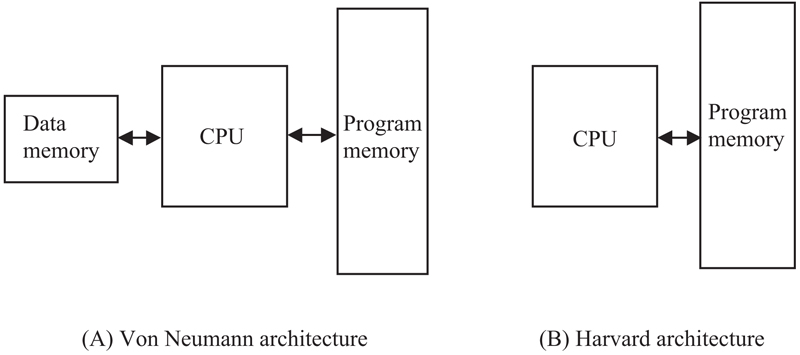
Usually, two types of architectures are used in microcontrollers (see Fig. 1.5): Von Neumann architecture and Harvard architecture. Von Neumann architecture is used by a large percentage of microcontrollers and here all memory space is on the same bus and instruction and data use the same bus. In the Harvard architecture, code and data are on separate busses and this allows the code and data to be fetched simultaneously, resulting in improved performance and simpler chip design.
Figure 1.5Von Neumann and Harvard architectures.
1.4.1. RISC and CISC
RISC (reduced instruction set computer) and CISC (complex instruction computer) refer to the instruction set of a microcontroller. In an 8-bit RISC microcontroller, data is 8-bit wide but the instruction words are more than 8-bit wide (usually 12-, 14- or 16-bits) and the instructions occupy one word in the program memory. Thus, the instructions are fetched and executed in one cycle, resulting in improved performance.
In a CISC microcontroller both data and instructions are 8-bit wide. CISC microcontrollers usually have over 200 instructions. Data and code are on the same bus and cannot be fetched simultaneously.
1.5. Summary
In this chapter we have looked at the main differences between microprocessors and microcontrollers. Additionally, we have briefly covered the various basic components of typical microcontrollers.
In the next chapter we shall be looking briefly at the architecture of the ARM family of microcontrollers, especially we will concentrate on the highly popular STM32F407 family of ARM microcontrollers since this is the microcontroller used in all the projects in this book.