Applying Flash Filters
Animating Filter effects with Motion tweens
Comparing the Adjust Color filter and Advanced Color Effects
Working with Blends
Setting and modifying Timeline Effects
Importing custom Timeline Effects
In this chapter, we'll introduce you to some of the key tools in the Flash authoring environment that support expressiveness — another term for creative options for designers. If you've worked with other graphics programs, you'll appreciate the creative potential of the Filters panel and the Blend menu built into the Property inspector. If you've never used a filter or heard of a blend mode, you'll be relieved to discover how easy it is to apply these features and will be amazed at how much they can do to enhance your projects.
Note
Flash CS3 now includes a handy option in the Filters panel that enables you to copy and paste Filter effects from one item to another.
Filters offer shortcuts for adding visual polish to your Flash designs. Rather than manually editing shapes to create drop shadows or adjusting gradient fills to create bevels, you can simply apply a live filter and use the built-in settings to adjust the final effect. Unlike Timeline Effects, filters are rendered on the fly and do not result in any additional symbols being generated and added to the Library. In addition, filters do not interfere with the "editability" of your content — you can always modify the original text or symbol instance without "breaking" the filter effect. Filters can be layered in any order, and you can make modifications to the individual filter settings at any time. You can also add or control filters at runtime with ActionScript, but for now we'll focus on applying filters in the authoring environment — which doesn't require any code! Filters are rendered as you add or adjust them so you can always see just what you'll get when the final movie is published.
As shown in Figure 12.1, the Filters panel is grouped with the Property inspector in the default Flash Workspace layout. To apply a filter, follow these easy steps:
Select an item on the Stage that is compatible with filters — a MovieClip instance, Button symbol instance, or text field.
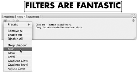
Open the Filters panel (or activate the Filters tab in the Property inspector), then click the plus symbol in the top-right corner to access the drop-down list of available filters.
After a filter is selected from the drop-down menu, it will appear in a live list on the left side of the Filters panel and you will see the filter effect (with default settings) applied to your selected item.
As shown in Figure 12.2, the settings for each filter are loaded into the main part of the panel when an applied filter is selected in the live list. The settings vary for each filter, but once you become familiar with the options, you'll find it easy to adjust individual filters. To remove a filter at any time, simply select the name of the filter in the live list and click the minus (–) symbol at the top of the panel.
Tip
Applied filters can be temporarily toggled off (and back on) to preview different filter combinations by clicking the check mark (or cross icon) that appears to the left of the filter name in the live list.
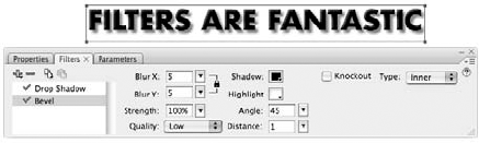
Figure 12.2. Individual settings for applied filters can be adjusted at any time by selecting a filter in the Filters panel live list.
The default filter settings (shown in Figure 12.3) are a good starting point, and in some cases they might even give you the result you want, though in most cases, you'll need to modify the settings to achieve a satisfactory final effect.
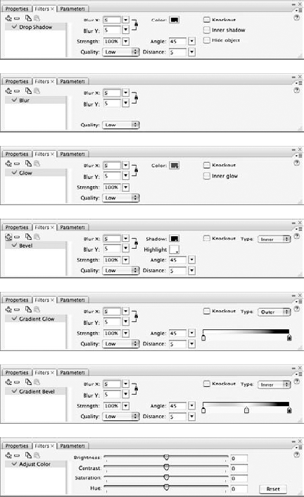
Figure 12.3. Some Filter effects have unique controls, but most are created with different combinations of a series of basic settings.
It would be an overwhelming task to document every combination of settings on every filter, but an overview of the main settings will provide you with some guidance for experimentation:
Blur X, Blur Y: Sets the distance that the edge of a shape will be extended horizontally (X) and vertically (Y) to create a graduated or softened edge for shadow, blur, bevel, and glow effects. This has the same effect as the distance setting in the Soften Fill Edges dialog box for shapes. The default blur distance is 5 and the range is from 0 to 100. By default, the lock icon is turned on to constrain the X and Y settings to the same value, creating a symmetrical, graduated effect. If you prefer to make the X and Y settings independent of each other, toggle the constrain option off by clicking the lock icon.
Strength: Sets the opacity of the rendered effect. The default setting is 100. The range is from 0 to 1,000. However, for all practical purposes, the effective range for most filters is from 0 (invisible) to 100 (solid center area with normal fall-off in graduated area). Increasing the strength of a filter beyond 100 percent adds opacity to the stepped (or softened) areas of the shape. The opacity is increased incrementally from the most solid area to the least solid area of the stepped edge.
Warning
At the maximum Strength setting of 1,000 percent, all the steps within the Blur distance of a filter are rendered at 100 percent opacity, which usually counteracts the visual impact of the filter. The result is an expanded solid shape with a slightly jagged edge, rather than a nice-looking shadow, blur, or bevel.
Quality: Sets the fidelity or smoothness of the rendered effect. This setting has a major impact on the performance of the published movie. By default, Quality is set to Low. As the quality is increased to Medium or High, gradients are rendered more smoothly and the steps in blurs are softened, but the performance of the final movie is reduced. Your Flash movies will perform better if you can achieve the visual effect you need by making adjustments to the Color and/or Blur settings rather than increasing the Quality setting.
Color: Click color chips to access currently loaded swatches and set colors used to render Drop shadow or Glow effects. The default solid color for Drop shadow is Black (#000000); the default solid color for Glow is Red (#FF0000). The solid color that is set with the Color chip will automatically fade from solid to transparent to create a soft glow or shadow effect. The Bevel filter requires both a Shadow and a Highlight color — by default, these are set to black (#000000) and white (#FFFFFF), respectively. The Gradient Bevel and Gradient Glow filters make it possible to add multiple colors to rendered gradient effects. Click the color anchors on the gradient strip to access currently loaded swatches and set control points in the gradient.
Note
The opacity of the center color anchor for Gradient Bevels and the left (outer) color anchor for Gradient Glows are fixed in position and set to 0 percent Alpha. The color of these pointers can be changed, but the Alpha level and anchor position can only be changed on the other anchors (or new anchors added to the gradient strip).
Angle: Sets the direction of offset to be applied with the Distance setting. If Distance is set to 0, changing the Angle (or degree of offset) will have no visible effect. The default is a 45-degree angle and the range is 0 to 360 degrees. You can change this setting by manually entering a number (decimals are allowed) or by dragging a small circle icon around a fixed 360-degree arc invoked by clicking the arrow (drop-down menu) icon next to the Angle value field. The higher the Distance setting, the more obvious the offset direction or Angle will be.
Distance: Sets the pixel value for the distance between the center point of the original item and the center point of the rendered filter (gradient). The default setting is 5 and the range is from −32 to 32 pixels. If the distance setting is 0, the rendered gradient and the original item will be center-aligned.
Warning
If the Distance setting is 0 and the Blur setting is less than 5, it can be hard to see a filter effect if it is rendered outside (or behind) the original item.
In addition to the adjustable settings, there are some check box options that expand the visual possibilities for filters:
Knockout: Converts the original shape into a transparent area, while leaving the rendered effect visible in any area that was not cut out by the original shape.
Filter types: For Blur and Drop Shadow filters, this is a check box to switch the rendered gradient from outside to inside the boundary of the original shape. For the multicolor gradient filters (Bevel, Gradient Glow, and Gradient Bevel), the options are listed in a drop-down menu that enables the filter to be set to render inside (Inner), outside (Outer), or inside and outside (Full) the boundaries of the original item.
Warning
The Bevel filter works best when left at the default Inside setting. Outside and Full bevels require some adjustment to create a realistic, dimensional result rather than a messy, doubled-up drop-shadow effect.
Tip
Inner Gradient Glow effects are easier to create using a custom gradient fill instead of applying the Gradient Glow filter with the Inner setting. A gradient fill will also be less demanding at runtime than a Gradient Glow filter.
Hide object: This option is the secret to creating sophisticated Drop shadows (as we describe later in this chapter). When Hide object is enabled, the original object disappears, but the drop-shadow is preserved.
Note
Although Hide object and Knockout both convert the original shape into a transparent area, they do not have exactly the same result. The Hide object option preserves the entire gradient area rendered by a filter effect, while the Knockout option creates a "cutout" effect when combined with filters that are not set to render inside the boundaries of the original shape. Although Hide object can be selected when the Knockout option is also selected, there is no visible difference to the rendered graphic. If you decide to use the Knockout option, it is best to uncheck the Hide object option to avoid rendering redundant filters at runtime.
The filter settings we have described thus far relate to the various gradient-based filters. As you can see from Figure 12.3, the Adjust Color filter settings are unique. The sliders available with the Adjust Color filter settings for adjusting various color qualities will be familiar to anyone who has worked in image editing programs like Photoshop or Fireworks. Flash updates the selected item on the Stage as you make color adjustments, so it is easy to experiment with the filter settings. However, it is important to know when to apply the Adjust Color filter and when to use the color controls available from the Properties panel.
One limitation of the Drop Shadow filter is that it does not have a built-in skew setting. The workaround for creating a drop-shadow with more depth illustrates how you can use the Hide object option and the Transform panel to enhance shadows created with the Drop Shadow filter. Here are the steps:
Place a Text field, Movie Clip, or Button instance on the Stage.
Create a new layer below the original content layer: Click the Insert Layer icon in the Timeline (or choose Insert

Copy the item from Step 1 to the new layer: Select the keyframe where the item exists and hold the Option key while dragging the keyframe content to the new layer, or select the item and use the copy command (Ctrl+C or

Select the duplicate item on the lower layer and use the Transform panel to apply a stretch and skew. As shown in Figure 12.4, we set the vertical scale to 130 percent and the horizontal skew to −45 degrees.
Open the Filters panel or activate the Filters tab in the Property inspector.
Click the plus symbol and select Drop Shadow from the filters list. In the Drop Shadow settings, select the Hide object check box. Otherwise, the default settings are a good place to start.
As shown in Figure 12.5, the default settings can be modified to create a softer shadow. In our example, the shadow Color was changed to medium gray (#666666), the Strength was set to 50 percent, and the Quality was set to Medium.
Note
We've included the finished file shown in Figure 12.5 on the CD-ROM so you can see how the shadow animates along with the original character. CharacterAnim_Shadow.fla and CharacterAnim_shadow.swf are both in the DropShadow subfolder of the ch12 folder on the CD-ROM.

You can add multiple filters to one item and they will be rendered in the order they appear in the live list, from top to bottom. Changing the order of filters by dragging a filter name up or down in the live list will change the final result of the combined effect, but the settings for each filter will be preserved and editable.
If you have created a special combination of filters or found a custom filter setting that you would like to reuse, the Presets option makes it easy to save and access your own list of filter effects.
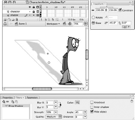
Figure 12.5. A Drop Shadow filter applied to the skewed symbol instance with the Hide object option enabled, and a few adjustments to the default settings, result in a realistic, dimensional shadow.
To save a filter setting or filter combo to the presets menu, follow these steps:
Select the item that has the filters and settings applied that you would like to save.
Note
All filters in the live list for the selected item will be saved with the preset — including any filters that are toggled off. When the custom filter is applied from the Presets menu to another item, the settings will be identical.
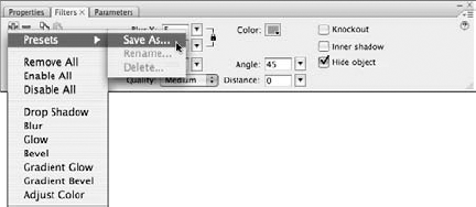
In the Filters panel, click the plus icon (+) to invoke the filter menu (as shown in Figure 12.6), and from the Presets submenu, select Save As.
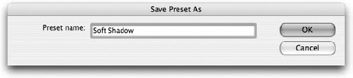
Enter a name for your custom filter settings or filter combo (as shown in Figure 12.7) and click OK.
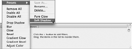
The named preset will be added to the bottom of the Presets submenu, along with any other saved Presets (in alphabetical order, as shown in Figure 12.8), and can be applied to other items.
Warning
When a Preset is applied to an item, any other filters that have been applied to that item will be cleared and replaced with the filters (and settings) that were saved with the Preset.
After a Preset is applied to an item, the settings can be modified on that item without corrupting the saved Preset. Unfortunately, the Presets list doesn't have a centralized edit option, but you can select the Rename or Delete option from the Preset submenu to load your list of currently saved presets into dialog boxes that enable you to rename an item or remove an item from the list. If you'd like to share your filter presets with someone else, all you have to do is provide them with the XML file that is saved for each preset in the Flash Configuration folder. The standard file paths for saved filter presets are as follows:
Windows:
C:Documents and SettingsusernameLocal SettingsApplication
   DataAdobeFlash CS3languageConfigurationEffectsfiltername.xml
Macintosh:
Macintosh HD/Users/username/Library/Application Support/Adobe/Flash
   CS3/language/Configuration/Effects/filtername.xml
Once the XML files are copied into the same location on someone else's computer, the presets will appear in her Presets menu when she starts Flash CS3. Filter swapping is an easy way to share creative resources and to keep effects consistent for projects that rely on filters for a specific look.
Although you may occasionally find it helpful to combine filters, it is best to try and achieve the result you want by first adjusting the settings of a single filter and/or modifying the symbol instance using the Color Effect settings in the Properties panel or the Transform tools. As with any intensive effect rendered at runtime, multiple filters will have a negative impact on the performance of the published Flash movie.
The Flash engineers have done a great deal of work to make it as easy as possible to combine filters with motion tweens for animated effects. The result is a very intuitive system that works behind the scenes to support tweens while preserving editable filter settings.
Note
Filters are not necessarily incompatible with shape tweens, but because filters can only be applied to symbols or text fields and shape tweens can only be applied to primitive shapes, filters and shape tweens never get a chance to work together. The only workaround for this rule is to create a shape tween inside of a Movie Clip and then apply a filter to the Movie Clip. In this case, the final visual result is a combination of a shape tween and a filter, but they remain on separate timelines.
You can apply a filter to an item and then tween it, or you can select an item that has been tweened and add a filter to enhance the motion — in most cases, you'll get exactly the animated effect you were hoping for. The only time you'll need to know what is going on behind the scenes is when you don't get the result you want on the first try.
Here are some notes that should help you troubleshoot if things go wrong when you try to combine filters and Motion tweens:
Filters "stick" to symbol instances, so if you insert a keyframe (with the same content as the initial keyframe), and set up a Motion tween, the settings and the stacking order in the live list will automatically match in the first keyframe and the last keyframe of the tween.
If you add a filter to a symbol in one keyframe of a tween, Flash automatically adds a matching filter with all the settings adjusted to create "no effect" to the symbol in the other keyframe. This is also called a "dummy filter" because it will have no visible effect on the symbol, but it is required to support the tween.
If you remove a filter from a symbol in one keyframe of a tween, Flash automatically clears the matching filter from the other keyframe.
If you apply different filters (or different combinations of filters) on two different keyframes and then apply a tween, Flash will analyze the symbol with the most filters and apply dummy filters to the symbol in the other keyframe to support the tween. The visual difference between the two symbols will be interpolated in the span of the tween.
You can modify filter settings to create a visual change from the first keyframe to the last keyframe in a Motion tween. The differences will be tweened evenly across the span unless you use easing to adjust the interpolation.
The knockout and type of gradient (such as inner, outer, or full) filter settings will not interpolate properly as part of a tween if they are set differently on the beginning and end keyframes. If the filter options in the first keyframe and the end keyframe of a tween are inconsistent and cannot be interpolated properly, Flash will apply the options set in the first keyframe to the frames in the span of the tween.
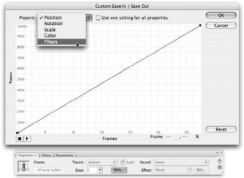
By default, the interpolation of any differences in filter settings from the first keyframe to the last keyframe will match the interpolation of the motion tween — that is, the filters will change at the same rate as any other characteristics of the item that have been modified to create animation in the tween. General Easing settings (adjusted in the Property inspector) will be applied equally to all changes in the characteristics of an item. As we described in the previous chapter, if you need more precise control over the interpolation of different aspects of a tween, you can use Custom Easing to set unique curves for Position, Rotation, Scale, Color, and/or Filters. To access Custom Easing controls, select the first keyframe in the motion tween, then click the Edit button to the right of the Easing controls in the Property inspector. As shown in Figure 12.9, the easing Property menu at the top of the dialog box enables you to load a unique interpolation curve for each of the various properties that can be animated in a tween. You can set a unique curve to apply to all properties, or set unique curves for selected properties, leaving the default curve for others.
The Adjust Color filter included in the Filter panel loads a set of controls for making color adjustment to Movie Clips, Button symbols, and text fields. The best way to explain these controls is to compare them to standard Flash color settings. Some of these controls are unique and some replicate settings available in the Color panel (for raw shapes, Shape Primitives and Drawing Objects) and/or in the Properties panel Color menu. These three different color control areas are shown in Figure 12.10, with an additional diagram to call out the features of the Color panel that overlap with slider settings for the Adjust Color filter.

Figure 12.10. The options for adjusting color in Flash include the Color panel (A), the Properties Color menu (B), and the Adjust Color filter (C) — which enables instance-level color transformations similar to the raw color edits supported in the Color panel.
The controls shown in Figure 12.10 enable various workflows for setting and adjusting color in the Flash authoring environment. In most cases, you will start with the Color panel (or Swatches panel) to choose and/or modify fill and stroke colors for initial primitive shapes or Drawing Objects. After the raw graphics are converted into reusable symbols, the Color controls available in the Property inspector and/or the Adjust Color filter can be applied to modify symbol instances without changing the original fill and stroke colors. The sliders and value fields for adjusting color with either of these options are easy to use and you will most likely achieve the result you want with just a little experimentation. However, there are important differences between the Color Properties settings and the Adjust Color filter settings, and the interaction of the different settings can become quite complex. To clarify the functions (and the advantages or limitations) of the various settings available with these two options, we have included a brief section for each.
Note
If you'd like to learn more about various color models and the differences between HSV/HSB (hue, saturation, value; or hue, saturation, brightness) and HSL (hue, saturation, lightness) color spaces, a good place to start is Wikipedia: http://en.wikipedia.org/wiki/HSB_color_space.
Figure 12.11 shows a sample of the range of color transformations that can be achieved with the sliders that load into the Filters panel when you apply the Adjust Color filter to Movie Clip instances, Button instances, or text fields.

Figure 12.11. The color controls loaded in the Filters panel when the Adjust Color filter is applied enable subtle color transformations of symbol instances and text fields.
Note
The grayscale version of the sample color transformations shown in Figure 12-11 gives you a hint of what is possible with the Adjust Color filter, but the color version of this figure included in the color insert in this book is much more informative.
Note
We have included the source file with the various transformed Movie Clip instances shown in Figure 12.11 on the CD-ROM. Open AdjustColorFilter.fla from the ch12 folder on the CD-ROM to see the samples in the Flash authoring environment. To see these same transformations applied to a sample bitmap, open AdjustColorFilter_bitmaps.fla from the same location.
Finally, you can make subtle adjustments (on an instance level) to Movie Clips, Button symbols, and text fields, without having to go back to the Color panel and change the stroke and fill colors of the original symbol. Unlike the Color control options in the Properties panel, the Adjust Color option in the Filters panel makes it easy to combine different types of color transformation without manually adjusting individual RGB values. By default, all settings are loaded as "neutral" — sliders are set to 0 so that no color transformation is visible on the selected item when the filter is first applied. Color transformations are applied for instant visual feedback as the slider controls or text values are adjusted. Filters apply on an instance level, and settings can be modified at any time by selecting an instance and choosing Adjust Color from the live filter list in the Filters panel. The following values can be applied individually or in combination to Movie Clips, Button symbols, and text fields:
Brightness: Alters the RGB values for the original color to make it appear lighter or darker without changing the hue. The range for filter Brightness is −100 to +100. The default or no change value is 0. The numeric value that appears in the Brightness field is added to the RGB values of the original color to create a new shade, within the minimum and maximum values of 0 and 255, respectively. For example, a red fill (255, 0, 0) set to +50 brightness will be transformed into light red (255, 50, 50). The same red fill (255, 0, 0) set to −50 brightness will be transformed into dark red (205, 0, 0). As shown in Figure 12-12, the results of adjusting Brightness in the Filters panel are different than the results of adjusting Brightness in the Properties panel.
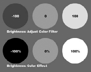
Figure 12.12. Numeric settings applied with the Adjust Color filter Brightness result in less extreme value changes than Percentage settings applied with the Color property Brightness.
Note
Although the range for the Brightness filter and the Brightness option in the Color menu might seem the same at first glance, the significantly different results that these two options achieve are due to one being a relative (or percentage-based) setting and the other being an absolute (or decimal-based) setting. The Brightness filter is applied as an absolute numeric value while the Color property Brightness setting is applied as a relative percentage-based value. Regardless of the original color, setting Color property Brightness to 100% shifts the RGB values to white (255, 255, 255) and −100% Brightness shifts the RGB values to black (0,0,0). Any other Brightness setting is calculated as the percentage between these two extremes, and the RGB values are transformed accordingly.
Contrast: At the minimum contrast setting of −100, all RGB values are forced to 64, 64, 64, making everything medium gray. The RGB values at the maximum contrast setting of 100 will vary depending on the original colors, but they will be forced closer to 0 or 255. The default or no change value is 0. The greater the numeric difference between RGB values, the greater the amount of contrast. In visual terms, light colors get lighter and dark colors get darker as contrast is increased, whereas all colors are brought closer to medium gray as contrast is decreased.
Saturation: Saturation can also be thought of as the intensity or purity of color. At the minimum saturation setting of −100, the image will be rendered in grayscale with no color intensity — similar to the hues found closer to the bottom of the color selection field in the Color panel. At the maximum saturation setting of 100, the colors will be as intense or as close to pure color as possible — similar to the hues found closer to the top of the color selection field in the Color panel.
Hue: The Hue slider has a different range than the other Adjust Color filter sliders. To span the full range of the 360-degree color wheel, the slider values are from −180 to 180. The default or no change value is 0. If you were looking at a real color wheel, reducing the hue value would be equivalent to moving counterclockwise around the wheel, while increasing the hue value would be equivalent to moving clockwise around the wheel. At either extreme (−180 or 180), the resulting color would be directly opposite the original color on the color wheel. The relationship of colors directly opposite on the color wheel is known as complementary.
Note
There are many books and online resources dedicated to color theory and there are many different versions of the color wheel. A good explanation and an illustration of an RBG color wheel can be found at www.color-wheel-pro.com/color-theory-basics.html. Color Wheel Pro is one of many software programs available to help designers create successful color schemes using color wheel relationships as a guideline.
Warning
Flash Filters (including the Adjust Color settings) are only compatible with Flash Player 8 and higher. If you plan to publish content for older versions of the Flash Player, you are limited to using the Color controls in the Property inspector to make adjustments to the appearance of symbol instances, or using the Color panel to modify the original stroke and fill colors in primitive shapes.
As we introduced in Chapter 6, "Symbols, Instances, and the Library," the Color menu in the Property inspector provides some options for modifying the appearance of symbol instances without changing the original symbol stored in the Library. After a Color adjustment type is selected from the Color drop-down menu, the controls needed to apply the color adjustment appear in the Property inspector. By default, "neutral" settings (0-percent change) are loaded as a starting point. After the values for a property are modified, they will be stored and loaded as the default when you select another instance. The settings loaded in the Property inspector for the items in the Color menu are simple and intuitive and enable you to make basic color adjustments using familiar controls:
Brightness: The Brightness Color property has the same range as the Brightness slider in the Adjust Color filter (−100 to 100); however, as we described previously, the Brightness property creates more drastic color transformations because it is applied as a relative or percentage-based value. At the minimum Brightness setting (−100), all RGB values are forced to black (0,0,0), and at the maximum Brightness setting (100), all RGB values are forced to white (255,255,255).
Tint: The color theory definition of a tint is a color produced by adding white to a pure color. The Tint property in Flash enables you to select any color (not just white) to "mix" with the original color. You can also select how much of the new color you want to mix with your original colors — from the lowest setting of 0 percent to the maximum setting of 100 percent. At the minimum setting, the original colors will be unchanged. At the maximum setting, the new tint color will completely replace all of the original colors. At the default setting of 50 percent, the rendered color values will be an even mix of the original colors and the selected tint color.
Alpha: This setting controls how opaque the selected instance will be. The values that control alpha are counterintuitive (as they are in the Color panel). At the minimum alpha level of 0 percent, the item will be transparent. At the maximum alpha level of 100 percent, the item will be fully opaque or "solid."
The Advanced Effect dialog box shown in Figure 12.13 includes two columns of settings for Red, Green, and Blue color channels, plus the setting for Alpha. This dialog box is invoked when a symbol instance is selected on the Stage by selecting Advanced from the Color drop-down menu on the Property inspector, and then clicking the Settings button. Although these columns may seem redundant at first, they actually provide very different options for controlling the appearance of instance color. The important difference between these two types of controls is that the first column creates relative changes by applying percentage-based adjustments, while the second column creates absolute change by adding or subtracting integer values.
Tip
The most recent transformation that was applied to an item using the simple Color controls will be preserved if you decide to switch to the Advanced option from one of the other options in the Color menu. The equivalent values will be transferred to the RGB or Alpha value fields in the Advanced Color Effects dialog box. This is a helpful way to get started with more complex transformations rather than starting from scratch. For example, you could select a Tint setting and then switch to the Advanced Color option to add an alpha setting that would be combined with the RGB values carried over from the original tint.

Figure 12.13. The Advanced Effect dialog box shown with the symbol instance testStar, with no effect applied
Other than playing with these settings, the easiest way to understand what some of the possible combinations produce is to dig out your calculator and find a chart of RGB color swatches (with decimal values rather than Hex values). By taking the RGB values in your original instance, multiplying them by the percentage entered in the relative value field, and adding the value shown in the absolute color field, you will arrive at the new RGB value that will appear in the symbol instance when the effect is applied. If this sounds confusing, read on.
Note
Because color examples are not very helpful illustrated in black and white, we have included the relevant graphics in a Flash file that you can open for reference. Compare the Advanced Color Effect (relative) layer with the Advanced Color Effect (absolute) layer in colorEdits.fla in the ColorEffectsVsFilters folder in the ch12 folder on the CD-ROM.
The first column of values adjusts the color of the instance relative to the percentages of color (or alpha) present in the original with a range of −100 percent to 100 percent. The default, or "no effect," setting is 100 percent. With these controls, 100 percent red does not change everything to pure red or 255 red, but rather it displays 100 percent of the current percentage of red in the existing colors. For example, yellow (255, 255, 0) cannot be made more orange by increasing the amount of red because 255 × 100 percent is still 255 — the maximum amount of red. However, if you reduce the percentage of green to 45 percent of the original value, the ratio of red will be increased, making the visible color shift to orange (255, [255 × 45 percent], 0 or 255, 102, 0).
This process of reducing the amount of the opposite (or complementary) color to alter the ratio of colors is called subtractive color adjustment, and it can be helpful to remember some basic color theory to predict how it will alter the appearance of your symbol instance. Because the color value changes that you make are applied to all the colors in your symbol, the overall effect can be more complex than just shifting one color in your palette. You will find, for example, that reducing the percentage of red and green to 0 for the testStar symbol instance (see the colorEdits.fla file on the CD-ROM) will cause the gray and white areas to shift to blue, whereas the red and green areas will shift to black, and the originally black areas will remain unaltered.
Because the maximum value for relative Alpha is also 100 percent, this control cannot be used to increase the alpha setting of an instance. For example, a symbol that has an alpha fill of 50 percent cannot be made to appear more solid because 100 percent of 50 percent is still only 50 percent alpha.
The settings in the right column are referred to as absolute color controls because they add or subtract color in concrete amounts regardless of the color values in the symbol instance. The scale of absolute color is from −255 to 255 and the default or "no effect" setting is 0. When absolute color is applied to a symbol instance, it is possible to make more drastic global color changes than you can make with relative color adjustments.
The effect of absolute color value changes made in the Advanced Effect dialog box is similar to the effect of using the Tint option of the Color menu. What makes these controls more advanced is that not only can you add a tint by increasing the value of certain colors, but you can also add an inverse tint by using negative values. So, for example, you could add a red tint to all the colors present in the testStar symbol instance, with the exception of white and pure red (which already contain 255 red), by entering a value of 255 Red, or you could add a yellow tint to all colors containing blue by entering a value of −255 Blue; this would make pure blue (0, 0, 255) turn to black (0, 0, 0), and white (255, 255, 255) turn to pure yellow (255, 255, 0).
Note
You can see the original testStar symbol instance and several modified examples, including those described in this section, in the Advanced Color Effect (absolute) layer of colorEdit.fla in the ColorEffectsVsFilters folder in the ch12 folder on the CD-ROM.
Perhaps one of the most unique feats that absolute values can perform is to make a symbol instance that contains alpha fills or strokes appear less transparent. Because the alpha settings are absolute, it is possible to shift an item with an original alpha setting of less than 100 percent to any opacity level between invisible (−255) and completely solid (255).
If you've entered negative values in the relative alpha setting, it is even possible to make an area with an alpha fill visible while solid areas are made invisible. Consider a shape that has an area of solid fill (100 percent or 255 alpha) and an area of transparent color (40 percent or 102 alpha). If this shape is converted into a symbol and then modified using the Advanced Effect options, you could enter a relative alpha value of −100 percent and an absolute alpha value of 255. When these effect settings are applied, the solid fill in the symbol instance would be invisible with 0 percent alpha (255 × −100 percent + 255 = 0), whereas the originally transparent fill would be visible with 60 percent alpha (102 × −100 percent + 255 = 153). Compare the modified testStar instance shown in Figure 12.14 with the original instance shown in Figure 12.13.
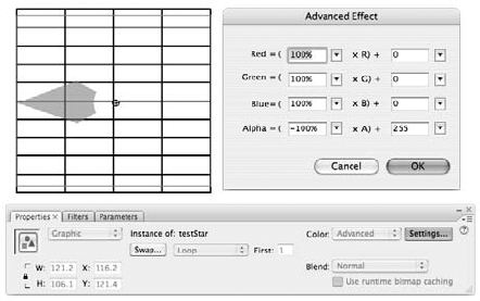
Figure 12.14. Using a combination of relative and absolute Alpha values, the transparency levels in the original testStar instance can be inverted.
The confusion that these settings sometimes cause has created debate about whether negative alpha settings can really be applied. As long as you can remember that outside of the absolute settings in the Advanced Effect dialog box, 0 percent alpha is invisible, whereas inside the Advanced Effect dialog box a 0 alpha setting is equal to no effect, you will be able to prove as we just did, that negative alpha effects can be used to invert alpha values, similar to the way that negative color effects can be used to invert color values.
If you use Photoshop or other image editing applications, you may be familiar with using blend modes, although for many people this remains a somewhat mysterious tool. Blends are rendering tools that analyze the pixel values of overlapping images (the blend image and the underlying base images) to create a rendered image that is a mix of the two. The type of blend applied will determine the formula used to generate the pixel values in the combined image. Blend modes can be applied to Movie Clip and Button symbol instances in the authoring environment using the Blend mode menu in the Properties panel (shown in Figure 12.15). The blend image will interact with any underlying images that it overlaps — even if they are not on the same layer.

Figure 12.15. The Blend mode menu is available in the Property inspector when you select a Movie Clip or Button instance
Tip
The dotted line breaks that separate the blend modes in the Blend menu may seem arbitrary, but they actually differentiate the blend modes into groups based on the type of effect they will have on images. Keep this in mind while you read the descriptions of each blend mode in the next section — you will start to notice similarities in the modes that are grouped.
Predicting the exact outcome of various blend modes is tricky because blends use different formulas on a pixel-by-pixel basis to mix the blended image with underlying images, and the result depends on the pixel values of both the underlying images (or base color) and the overlapping image (or blend color). The most common advice for working with blends is to experiment until you get a result that you like — we encourage you to do exactly that! However, it is helpful to have some idea of how each blend works and what visual problems they can solve. Compare Figure 12.16, which shows two source bitmaps (left and center), overlapped with blend mode set to Layer or Normal (right), to Figure 12.17, which shows how the images appear with Flash blend modes applied to mix the images in various ways.

Figure 12.16. A base image (left) and a blend image (center) overlapped with blend mode set to Normal or Layer create a standard layered graphic with no mixing of pixel values (right)
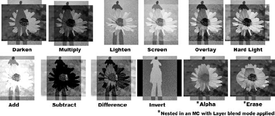
Figure 12.17. The 12 different effects that can be created by applying Blend modes to layered images — the results will vary depending on the images that are combined, but the formula used for each blend type is consistent. Unlike other blend modes, the Alpha and Erase blend modes require a nested structure with a Layer blend applied to the parent symbol instance.
Note
You'll notice that we didn't include an image in Figure 12.17 to illustrate the Layer blend mode applied by itself. That is because the Layer blend mode has no effect, unless it is combined with a nested Erase or Alpha blend mode.
The Blend modes available in Flash include the following:
Normal: The default blend mode for new symbol instances. No interpolation is applied and pixel values are left unchanged.
Layer: Creates no visual effect on its own, but is required for Alpha and Erase blend modes to work.
Darken: Compares the brightness of the pixels in the base image with the pixels in the blend image. Pixels in the base image that are lighter than the blend image are replaced with pixels from the blend image. Pixels in the base image that are darker than the blend image are left unchanged.
Multiply: Multiplies the RGB values of the pixels in the base image with the pixels in the blend image. The resulting pixels are a darkened combination of both the base image and the blend image. Multiplying any color with black results in solid black; multiplying any color with white leaves the pixels unchanged.
Lighten: Compares the brightness of the pixels in the base image with the pixels in the blend image. Pixels in the base image that are darker than the blend image are replaced with pixels from the blend image. Pixels in the base image that are lighter than the blend image are left unchanged. The blend image always disappears when it's layered over white.
Screen: Analyzes the color values and multiplies the inverse of the blend and base colors. The resulting pixels are a lightened combination of both the base image and the blend image. Screening with black leaves the base image unchanged. Screening with white produces solid white. The blend image always disappears when it's layered over white.
Overlay: Pixels are screened or multiplied depending on the pixel values in the base image. If the base color is lighter than mid-gray, the image is lightened (screened), and if the base color is darker than mid-gray, the image is darkened (multiplied). The blend image overlays the base image while preserving the highlights and shadows of the base image. The resulting image is an even blend of the base image and the blend image, usually with increased contrast in both images. Overlaying black results in a shaded version of the base image. Overlaying white results in a bleached version of the base image. The blend image disappears when it's layered over any pure color (black, white, pure red, pure green, etc.).
Hard light: Pixels are screened or multiplied, depending on the pixel values in the blend image. If the blend color is lighter than mid-gray, the image is lightened (screened). If the blend color is darker than mid-gray, the image is darkened (multiplied). The base image is mixed with the blend while preserving the highlights and shadows of the blend image. Overlaying pure black or pure white results in solid black or solid white, respectively.
Add: Adds the color values of the blend image to the color values of the base image. The result is a bleached-out combination of the two images. Adding pure white results in a solid white image; adding pure black has no effect on the base image.
Subtract: Subtracts the blend color value from the base color value. The result is a darkened combination of the two images. Subtracting pure white from any color results in a solid black image. Subtracting pure black has no effect on the base image.
Difference: Analyzes the color values in the base and the blend and subtracts the brighter values from the darker values. The result is a reversal of color values. Black blended with any color has no effect. White blended with any color inverts the color. The resulting image looks like a film negative of the combined images.
Invert: Inverts the base image in any areas overlapped by the blend image. The contents of the blend image have no bearing on the transformation of the base color values — the blend image acts merely as an "active area" for the inversion effect.
Alpha: Alpha blend mode can be used to apply the contents of a nested Movie Clip with alpha areas as a mask for an image in a parent Movie Clip with Layer blend mode applied.
Erase: Erase blend mode can be used to apply the contents of a nested Movie Clip as an eraser to cut out an area of an image in a parent Movie Clip with Layer blend mode applied.
Tip
Using a solid fill with Alpha set to 0% in an Alpha blend will have the same effect as using a solid fill in an Erase blend.
That's a lot of visual calculation to try and imagine without actually using blends. The steps for applying the "basic blends" (all but Alpha and Erase) are straightforward:
Select a Movie Clip or Button symbol instance that you want to use as a blend image to layer with underlying base images.
Tip
Images on layers above the layer with the blend symbol instance will not be transformed by the blend mode. Don't forget that you can use the Modify
Click the Properties tab in the Property inspector, and from the Blend menu, select a blend type.
That's it! You can see how the blend image interacts with different base images by dragging it to overlap other images in your Flash authoring environment. The Color menu and Filters can be used in combination with blend modes to get different effects. All of these effect tools will interact to transform graphics rendered in the authoring environment, but they will remain editable and each can be adjusted independently on an instance level. You can apply multiple blend modes on the same layer, but only one blend mode to any single symbol instance. The only compound blend modes are Alpha and Erase, which must be applied on a symbol timeline and combined with a Layer blend mode on the parent symbol instance, as we describe in the next section.
Warning
The background color of your Flash movie will interact with blend modes too. This is helpful to remember if the blend image is larger than the base image and you start getting unexpected results in the overhang areas. Applying a Layer mask to the blend image so that it is trimmed to match the base image will remove any unwanted overhang areas that are mixing with the background color.
Alpha and Erase blends are a great complement to Flash's standard masking tools — which can be counterintuitive at times. If you want to create a cutout in a shape using a traditional mask, you actually have to create a shape on a mask layer that covers all the areas except the area you wish to cut out. If you have been working in Flash for a while, this workflow is probably second nature, but when it comes to more subtle mask effects, like gradients or irregular shapes, it can be a headache to have to reverse-engineer a mask graphic. With Alpha blends, what you see is what you get — or rather, what you don't see is what you won't get! The steps for creating a compound blend are as follows:
Create a Movie Clip with content that will function as the base image (or convert an existing graphic that you want to mask into a Movie Clip).
Open the Movie Clip in Edit mode to access the Movie Clip timeline: Double-click an instance on the Stage or the symbol name in the Library list.
Create a new layer on the Movie Clip timeline above the existing content that will be the base image for the Alpha or Erase blend. To protect the base image(s), you may want to lock all layers but the new layer.
Note
The base image or color can be any graphic type — primitive shape, Drawing Object, bitmap, or symbol instance — as long as it is nested inside of a Movie Clip or Button symbol. The blend image has to be a Movie Clip or Button symbol instance.
In the new layer, create a graphic that will act as a mask — blend masks are the opposite of normal Flash layer masks in that the content in the Alpha or Erase blend symbol instance will define an area to make invisible in the base image rather than define an area to make visible.
Warning
Any content in a symbol instance with an Erase blend mode applied will define the area to be punched out of (or erased from) the underlying base image. The content of a symbol instance with an Alpha blend mode applied will have no effect unless it contains areas with transparency — the amount of information erased from the base images will match the level of Alpha transparency in the blend symbol instance. A symbol instance with content set to 0 percent Alpha and applied as an Alpha blend will have the same effect as an Erase blend.
Convert the content on the blend layer into a Movie Clip or Button symbol.
Select the symbol instance and position it on the Stage (still on the base image Movie Clip timeline) to overlap the base image so that it defines the area you want to Erase or Alpha out, then use the Blend menu in the Properties panel to apply an Alpha or Erase blend mode. The content of the blend image will disappear, but don't panic — continue to the next step to complete the compound blend.
Return to the Main Timeline: Double-click an empty area of the Stage or use the Scene button above the Timeline.
Select the parent symbol instance (that contains your base image and the currently invisible blend image), and use the Blend menu to apply a Layer blend. (If you opened the base symbol from the Library in Step 2, make sure you have an instance dragged onto the Stage on the Main Timeline so you can apply the Layer blend mode to the instance.)
Voila! You should see the content of your blend image punched out (Erase blend) or rubbed out (Alpha blend) of the base image — either the background color of the Flash movie or any underlying images on the Stage will be visible through the empty areas created in the base image.
In addition to supporting a more intuitive workflow for creating masks and enabling Alpha-based masks, compound blends can be used to create animated transition effects. Continue to the next section if you would like to try using an Alpha blend to create an animated color fade effect.
The following example uses an animated Alpha blend to selectively fade out a black and white image to reveal a color image. The trick for this effect is to use two instances of the same color image, with the Adjust Color filter applied to make one instance a grayscale version. There are a lot of steps, but the final file structure is straightforward and the effect is pretty cool, so let's get started:
Open a new Flash document.
Import a color bitmap and convert it to a Movie Clip (or place an existing Movie Clip instance on the Stage — preferably one with bright colors).
Place two instances of the Movie Clip on the Stage so that they are layered and aligned — select both instances and use the Vertical Center and Horizontal Center align commands.
Select the topmost Movie Clip instance and use the Adjust Color filter to set the Saturation of the image to −100 — this will drain the color out so that it looks grayscale.
With the grayscale Movie Clip instance still selected, use the Blend menu in the Properties panel to apply Layer blend mode. You won't see any visible change yet.
Double-click the grayscale Movie Clip instance to access the Movie Clip timeline in Edit mode.
Create a new layer at the top of the layer stack in the Movie Clip Timeline. Lock the other layer(s) with the bitmap or graphics you plan to use as a base image.
Select the Oval tool (O) in the Tools panel and set the Fill color to use a default radial gradient. Use the Color panel to apply 0 percent Alpha to the right color anchor. This should create a circular gradient fill that has a transparent center that fades out to black. Set the stroke color to None.
Click and drag on the Stage to create a circle that covers only a small area in the center of the original image — in our file, the circle image was 100 × 100 pixels.
Select the new circle and convert it into a Movie Clip named
alpha circle.Use the Blend menu in the Properties panel to apply Alpha blend mode to the
alpha circleMovie Clip instance. The circle Movie Clip will disappear, but don't panic. As you can see by the filled keyframe on the layer, the content is still there and you can select it to see the selection outline for the invisible instance.Double-click the
alpha circleinstance to access the Movie Clip timeline and insert frames (F5) to extend the span of the circle graphic to frame 20. Convert frame 20 into a keyframe (F6).Select the circle graphic in keyframe 20 and use the Transform panel to increase the size of the circle so that it is larger than the bitmap base image. We scaled the circle up to 400 × 400 pixels.
Select keyframe 1 (still in the alpha circle timeline), and apply a Motion tween to animate the small circle scaling up to the size of the larger circle in frame 20.
In order to see the Alpha blend applied as a mask, you have to return to the Main Timeline (click the Scene button).
The grayscale bitmap image should now have an area in the center that is "erased" in a soft, gradient circle that allows some of the color image to show through.
The animated effect will only be visible in the published .swf file or the Test movie environment. Use Ctrl+Return or
Note
To see the final result of our example file, open
anim_Alpha_blend.swffrom theBlendsfolder in thech12folder on the CD-ROM. To analyze the file structure, openanim_Alpha_blend.flafrom the same location.
You can always go back inside the nested symbols to modify the level of alpha in the blend image or change the style of fill from a radial gradient to a linear gradient or even a solid fill (with alpha set to less than 100 percent). The level of masking will match the level of alpha in the contents of the Alpha blend symbol instance. Alpha blends can be used to mask any type of image — even bitmaps or primitive shapes. The only requirement is that the Alpha blend must be applied to a symbol instance and that symbol instance must be nested inside a Movie Clip with a Layer blend applied. This is just one way of using a blend mode to create an interesting visual effect. There are many other possibilities, and once you understand the workflow for applying basic and compound blends, the rest is just a matter of experimentation!
Flash MX 2004 introduced a new way of creating animation and visual effects. Rather than manually placing symbol instances on the Stage and inserting tweens on the Timeline, you can simply select an item (shape or symbol) on the Stage and choose a static or animated effect from the Timeline Effect menu. The specific functionality of manual tweens and the differences between Shape tweens and Motion tweens are relatively easy to explain. Timeline effects are a bit more of a muddle. They can be used for effects on static graphics or for adding multiframe animation. Some Timeline effects can only be added to symbols, but most can be added to either shapes or symbols. By default, most Timeline effects render as Graphic symbols on the Timeline, but if they're applied to a Movie Clip symbol, they will inherit that behavior. The only definitive thing we can say about Timeline effects is that they offer some very intriguing possibilities for noncoders to add more sophisticated graphics to their projects. With prebuilt JavaScript-Flash code, Timeline effects make it possible to select an item on the Stage and control its appearance and motion by simply making selections in a Settings dialog box. After you preview and apply your chosen settings, Flash automatically converts the selected item to a Graphic symbol and renders a nested symbol on the Stage and frames on the Timeline to hold the finished Effect or animation. Easy so far, right?
The Timeline effects listed in the application menu under Insert
The magic of Timeline effects is simply that they can save you a lot of time and make it much less painstaking to change the timing or placement of a rendered animation or visual effect. The mayhem of Timeline effects comes in when you look in your project Library. Adobe has done a great job of organizing this automated process, but you may still be a little confused by all the symbols and folders that show up in the Library panel after you've applied a few Timeline effects.
If you're planning to just apply some effects, publish an .swf file and move on; you needn't worry about understanding the symbol structures and editing "rules" for Timeline effects. However, if you plan to integrate Timeline effects with other animation that you've created, or if you decide you want to edit an item after an effect has been rendered — which of course you will! — we hope this section makes the process a little less mysterious.
You can do great things with Timeline effects. But before you vow never to use a manual Motion tween again, we'd like to give you a few cautionary notes to consider:
Symbols with Timeline effects added to them cannot be opened in Edit mode without breaking the settings option. You can still edit the nested symbols in a Timeline effect, but you have to open them from the Library list rather than from the instances on the Stage. Unfortunately, the changes you make to the source symbol may not always be carried over to all instances in the nested effect symbol until you preview it again in the Settings dialog box.
Practically, you are limited to the options available in the Settings dialog box for each Timeline effect. So for example, if you decide you prefer to have a skewed drop-shadow, you will either have to break the settings option to edit the symbols individually, or you'll have to make your own layered symbol instances.
In order to layer multiple Timeline effects (such as adding a fade Transition to an item with a Drop shadow), you have to manually nest the Timeline effect Graphic symbols inside of other symbols.
Timeline effects are generally rendered as nested Graphic symbol structures. The benefit is that you can see animated effects by scrubbing the Timeline. The drawback is that you will end up with redundant symbols in your Library if you apply a Timeline effect to an existing Graphic symbol. Also, your animation will be tied to the Timeline unless you nest it inside a Movie Clip symbol.
Timeline effects add auto-named symbols and layers to your project file, which can make it harder to keep your naming systems consistent and meaningful.
You can rename generic symbols and folders in your Library and layers in your Timeline that have been generated by a Timeline effect. However, if you edit the settings on any of your Timeline effects, these items will revert to the generic naming sequence.
You must apply (or reapply) Behaviors after you have added Timeline effects. Timeline effects added to an item with an assigned Behavior will nullify the action controlled by the Behavior because it changes the symbol type of the item.
Now, if that wasn't enough to dissuade you from using Timeline effects — and it shouldn't be, unless you are a symbol structure and naming purist — we'll move on to investigate some of the animated Timeline effects that are included with Flash.
The Timeline effects that ship with Flash are organized into three categories in the Timeline Effects menu (under Insert in the application menu or in the contextual menu for items selected on the Stage):
Assistants: These Effects give you a more streamlined way to complete authoring tasks that you could otherwise accomplish using the Transform and Align panels with Color effects or filters.
Copy to Grid: This makes it possible to duplicate and distribute multiple copies of an item in rows and/or columns. This effect does not make any change to the appearance of the item, but it gives you the controls you need to create an organized layout of multiples (see Figure 12.18).
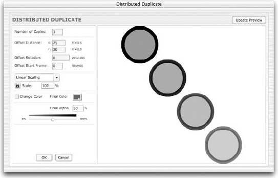
Distributed Duplicate: This effect, demonstrated in Figure 12.19, creates a series of copies of an item, distributed along a tangent that can be set by entering the x and y offsets. The copied items can also be shifted in scale, color, and transparency.
Effects: These Effects modify the graphic content of your original item:
Blur: Adds something similar to an animated soften fill edges effect with settings for duration, scale, resolution, and direction. Could also be described as an animated "glow" or "drag" effect.
Drop shadow: Adds a static duplicate "shadow" with settings for color, alpha, and offset. This sounds as if it's an effect that you would use a lot, but the truth is, you will most likely get better-looking drop-shadows if you use the Drop Shadow filter or make them manually.
Expand: This is hard to describe, but the best analogy we can give in print is filling a balloon with water. You can specify the direction and amount for an item to stretch and/or squash over a given span of frames. If you want to make an item look as if it is breathing, this is the effect to use.
Explode: If you've been waiting to blow up some logos in Flash, now's your chance! You can specify the size and direction of the pieces and even how far and how fast they fly.
Transform/Transition: These Effects are used to add animated changes to the display or position of your original item over a specified range of frames. The most subtle and flexible group of Effects, these are the two that you'll use most often to save production time.
Transform: Change position, scale, rotation, color, and/or alpha
Transition: Wipe and/or Fade an item in or out

The static Timeline effects include those listed in the Assistants category, plus the Drop Shadow effect. The Drop Shadow filter produces better visual results and is easier to edit than the Drop Shadow Timeline effect, so for all practical purposes, this Timeline effect is deprecated.
The Timeline effects in the Assistants category are still useful and easy to apply:
Select an item on the Stage — it can be a shape, Drawing Object, or symbol. As with tweens, it is best to apply Timeline effects to items that exist on their own layer.
Use the Insert menu (or the contextual menu) to access Timeline effects. Choose a category and select the effect you want to apply.
The specific result of frames and symbols rendered by different Timeline effects will vary, but the steps for adding a Timeline effect are consistent.
To add an animated Timeline effect to a shape or symbol, follow these steps:
Select an item on the Stage — it can be a shape or a symbol. In our example, we used an imported bitmap. As with Shape or Motion tweens, it is best to apply effects to items that exist on their own layer.
Warning
Although you can select an item in the first keyframe of an existing Motion or Shape tween and apply a Timeline effect to it, in most cases the tween will be broken when the Timeline effect is rendered because the item will be moved to a new layer. As we discuss later in this section, it is best to render the Timeline effect on a separate timeline if you want to combine animation methods.
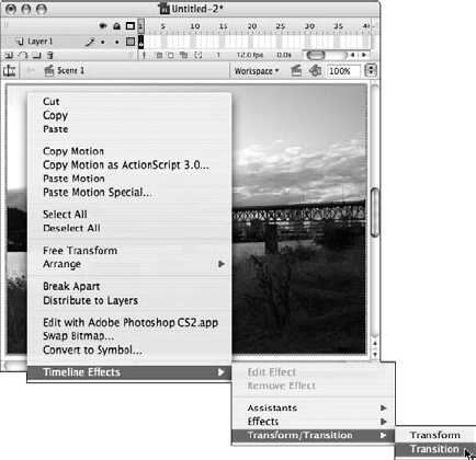
Use the Insert menu (or the contextual menu) to access Timeline effects. Choose a category and select the effect you want to apply. For this example, we'll apply the Transition effect (as shown in Figure 12.20).
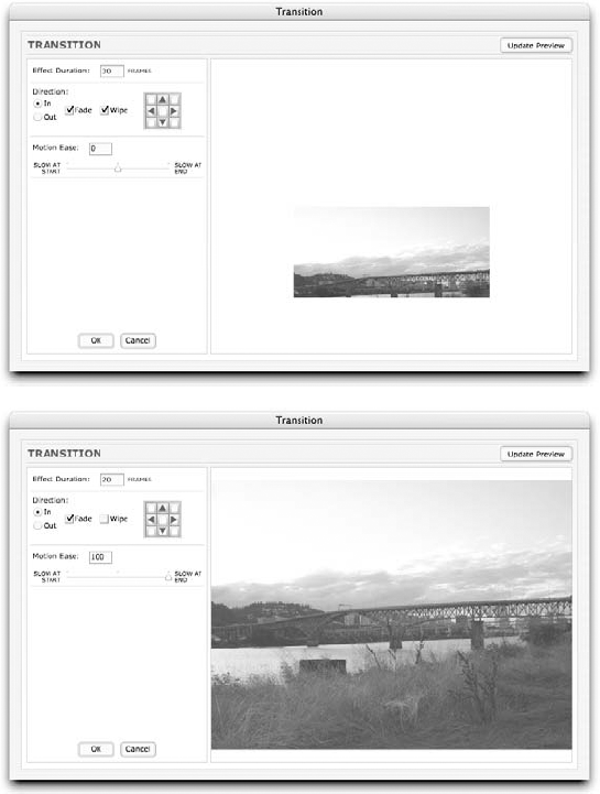
In the Settings dialog box, a preview of the animation will be rendered with the default settings. Modify the settings and use the Update Preview button to test the result until you achieve an effect that you like. (Our Transition example is shown in Figure 12.21.)
Click OK to close the Settings dialog box and render the effect.
If you have applied a complex Timeline effect, it may take a few seconds for Flash to render the symbols and insert the frames on your Timeline to hold the effect.
Note
If there is no other artwork on the layer with the item to which you added a Timeline effect, Flash simply renames the layer when the effect is applied. If there are other symbols or artwork on the layer with the item to which you added the Timeline effect, Flash moves the item to a new layer when the effect is applied. This can lead to duplicate layer names that should be manually changed to keep the structure of your document clear.
After the effect is finished, you will see a layer in your Timeline auto-named to indicate the effect that was rendered and the sequence that it was rendered in during your project authoring process. In our example, the layer is named
Transition 1(see Figure 12.22).
Figure 12.22. After a Timeline effect is rendered, you will see a newly named layer for the animated frame span, and you will find symbols in the Library that were generated by Flash to create the effect from your original item.
Tip
If you have created an animation that starts with an alpha setting of 0, you won't see anything on the Stage in the first frame of the new animated frame span. However, if you click the frame, you will see the blue selection box on the Stage to indicate the position of your "invisible" artwork.
A frame span will extend on the Main Timeline for the duration of the animation if you applied an animated effect to a shape, bitmap, Graphic symbol, or Button symbol. You can preview the animation by scrubbing the Timeline in the authoring environment.
Note
If you apply an animated Timeline effect to a Movie Clip symbol, the animation span is rendered on a Movie Clip timeline, so you will not see frames added to the Main Timeline and you will have to preview the animation in Test Movie mode.
As shown in Figure 12.22, you will also find new symbols that Flash rendered to create the Timeline effect added to your Library list. These symbols are given default names that will indicate the type of effect applied and the sequence that it was created in during an edit session.
Warning
This is the only time in this book that we will advise you not to change the default symbol and layer names right away. If you decide to edit the settings for your animated effect, the symbols and layers rendered by Flash will be renamed anyway. The best approach is to rename these items only as a final step in your editing process.
And there you have it — a lovely fade transition that can be adjusted without touching the Timeline or moving any keyframes. If you want to change the pacing or the look of the Timeline effect, use the Edit Effect option in the Timeline effects menu to open the Settings dialog box again. If you decide that the effect is not really what you wanted, use the Remove Effect option in the Timeline effects menu to get rid of it without deleting your original item.
If you are accustomed to working with tweened animation or compound symbol structures that you have made manually, there are a few differences that will come up when you start working with Timeline effects. Although the symbols added to your Library when you apply a Timeline effect have the same icon as any other Graphic symbol, there are some special rules about how they can (or cannot) be modified.
Flash renders an effect based on the settings you enter in the Timeline Effect dialog box, so once the Graphic symbols for the effect have been rendered, you cannot edit the top-level Graphic symbol directly. Although you can't open the top-level Graphic symbol (with the final rendered effect) in Edit mode without disabling the Edit Effect option, you can edit the nested Graphic symbols that are stored in the Effect folder. In most cases, the changes you make to the nested Graphic symbol are passed on to all instances used in the final rendered effect. However, in cases where the effect required incremental mathematical adjustments (such as on a Color Change), you have to use the Edit Effect command to open the Settings dialog box so that the effect can be re-rendered in the Preview window (it will automatically update to include any changes you made to the nested symbols in the Library). You can make additional changes to the effect using the options in the Settings dialog box, or you can simply click OK to close it and go back to the Stage — where you should now see the changes passed on to all of the instances of the effect.
You can also use the instance-editing options available in the Property inspector and the Transform panel to adjust the appearance of a rendered (or top-level) Timeline effect symbol without disabling the Edit Effect option. With the Free Transform tool added to the mix, you should be able to squish, stretch, rotate, tint, and otherwise adjust rendered Timeline effect symbols to suit your fancy. If you are working with a Timeline effect nested in a Movie Clip, you can also use Filters to increase your creative options.
Using Custom Timeline Effects, by Samuel Wan
Authors' Note: Although it is beyond the scope of this book to describe the steps involved in actually scripting your own Timeline effects, we can tell you how to use custom effects that other developers have made. One of the developers making cool effects is Samuel Wan. He has kindly agreed to let us include the code for one of his very first Flash Timeline effects on the CD-ROM. This brief tutorial is adapted from Sam's notes on how to install and use his "Jitter" effect. We hope you will be able to follow these same steps to use other custom effects available from Adobe or from generous developers in the Flash community.
The first step to using a custom Timeline Effect is to find the files that Flash needs to make the Effect Settings appear in the authoring environment and to render the final Effect. Unless you happen to know some brainy coders, the best place to look for new Timeline Effects is on the Adobe Web site.
The two files you will need to install any custom effect are
An XML file that describes the parameters or "properties" of the effect and how the parameters can be customized. These files can be recognized by the .xml file extension.
A JavaScript-Flash file that implements the required methods for manipulating the Flash-authoring tool based on parameters specified by the XML file. These files can be recognized by the .jsfl file extension.
Note
We have included
Jitter.xmlandJitter.jsflon the CD-ROM in theTFX_customsubfolder of thech12folder. To see the rendered effect, openJitterSample.fla(or .swf) from the same location.Both of these files have to be saved in your Flash CS3 Effects folder so that a custom effect can be applied in the authoring environment:
The standard directory path on Windows is:
C:Documents and Settings(username)Local SettingsApplication
DataAdobeFlash CS3(language)ConfigurationEffects
The standard directory path on Mac is:
[Start up drive]Users[Your username]LibraryApplication
SupportAdobeFlash CS3[Your language]ConfigurationEffects
After you save the XML file and the JSFL file to the Effects folder on your system, you will need to restart Flash to see the custom effect in the Timeline Effect menu.
The steps for applying a custom Timeline effect are the same as the steps for applying a built-in Timeline effect, but the settings available for the effect will be unique. To apply the Jitter effect, follow these steps:
Select an item on the Stage (a shape or a symbol).
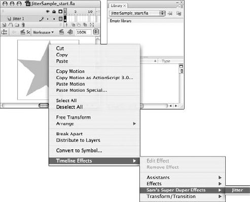
Access the Timeline Effect menu from the Insert menu or from the contextual menu. As shown in Figure 12.23, a new category of effects has been added — Sam's Super Duper Effects are now listed along with the other categories that were described earlier in this chapter. Select Sam's Jitter effect.
A Settings dialog box appears on Stage so that you can enter values to control the rendered Jitter effect (refer to Figure 12-24).
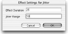
Figure 12.24. The Settings dialog box for custom Timeline effects may have a more generic appearance than the Settings dialog box for built-in Timeline effects.
Note
As shown in Figure 12.24, the Settings dialog box for the Jitter effect looks quite different than the Settings dialog box used to apply the Transition Timeline effect we showed you earlier in this chapter (see Figure 12-21). This is one of the quirks of custom Timeline effects. Some developers will include an .swf control for the settings that generates a dynamic preview of the effect, while others will only build the .jsfl and .xml files, which results in a more generic-looking Settings dialog box — similar to the dialog box for drawing tool settings. The purpose and effect of the settings are the same in either interface. The main difference is that you can't preview the effect before you apply it unless you're using an .swf settings dialog box. Fortunately, it is easy to remove an effect at any time, so the generic settings box is not a huge problem — most custom effects will be worth the extra trouble of testing and removing a few different settings before you decide what works best.
After you enter values for the frame duration of the effect and the pixel offset, or the amount of jitter, click OK.
The animation will be rendered on the Timeline in a layer called "Jitter 1." If you look in the project Library, you will see that the original selected shape has been converted to a Graphic symbol ("Symbol 1") and nested in an animated Graphic symbol ("Jitter 1"), both now stored in the Library (refer to Figure 12.25).

Note
To see the final animated Jitter Effect, have a look at the JitterSample.swf file in the TFX_custom subfolder of the ch12 folder on the CD-ROM.
That seems like a lot of steps, but it certainly takes less time to install a custom effect than it does to make one from scratch! We hope there will be many more useful and creative effects available that will open new possibilities for your Flash designs. You can continue to save other custom effects files to your Effects folder and they will be added to the Timeline Effects menu.
Warning
Obviously, it would be a big mistake to save a custom effect file to your Effects folder if it had the same name as an existing effect. Unless you want to overwrite existing Timeline effects, make sure you're using unique names for any custom effects that you add. If you'd rather not change the name of an effect, simply add a unique number to the effect name to avoid overwriting other files with the same name.
If you decide you don't need an effect anymore, or if your Timeline Effect menu gets too cluttered, simply remove the relevant .xml and .jsfl files from the Effects folder (save them somewhere else if you liked the effect; trash them if you didn't). The next time you restart Flash, the effect will no longer show up in the menu.
Note
We'd like to know what you think about this chapter. Visit www.flashsupport.com/feedback to send us your comments.
The intuitive Filters panel supports a variety of Filter options, including layering filters and saving presets, without any scripting or special timeline structures required.
The built-in Filters are somewhat limited on their own. The good news is that Filters can be combined with Blend modes, Properties, Transform tools, Timeline Effects, and tweens with Custom Easing curves to expand their potential well beyond the default settings.
The new option to Copy and Paste Filters from one item to another is a time-saver if you want to reuse a specific Filter set on multiple elements in your movie.
Custom Easing extends the power of easing beyond linear Ease In and Ease Out — the Custom Easing dialog box launched from the Properties panel enables you to control easing with a curved interpolation path that can have multiple control points for adjusting animated elements. You can apply a single curve to all properties of the tween, or create unique curves to adjust the progression of various properties individually within the same tween.
The Blend mode menu in the Properties panel brings some of the power of Photoshop into the Flash authoring environment — graphics can be blended in more subtle and interesting ways.