
Chapter 7
Wielding the Pen and Anchor Point Tools
IN THIS CHAPTER
![]() Understanding the foundational role of the Pen tool
Understanding the foundational role of the Pen tool
![]() Drawing curves
Drawing curves
![]() Adding, deleting, moving, and connecting anchors
Adding, deleting, moving, and connecting anchors
![]() Editing anchors with the Anchor Point tool
Editing anchors with the Anchor Point tool
In this chapter, I show you how to use the Pen tool to draw, use the Direct Selection tool to select and move anchors, and use the Anchor Point tool to tweak curves you've created with any tool (even shapes).
These techniques can be used to create a drawing from scratch. More typically, you will deploy them later in the design process, after you use quicker and easier — but less precise — tools to rough out your illustration.
A typical workflow (to the extent that there is such a thing) might start with one of the basic shape tools (see Chapter 4) or with the Pencil, Curvature, or Paintbrush tools (see Chapter 8). Or you might draw a sketch on a mobile device in Adobe Draw — Adobe’s free app for sketching vectors on iOS or Android devices — bring that sketch into Illustrator, and then touch it up using the Pen tool with the techniques I cover in this chapter.
The point is, at the end of the day, you need the level of power and detail of the Pen tool, as well as the other path-editing tools you explore in this chapter, to put the finishing touches on most projects. And some drawings, such as the waveform you explore here, are best created from the start by using the Pen tool.
Editing Anchors
We start our journey into editing anchors by demystify vector curves. A vector curve breaks down to a collection of anchors and defined path segments. You might, for example, get inspiration from seeing an adorable slug, and quickly sketch it with the Paintbrush tool. That happens. Maybe not every day, but after a rain.
If I use the Selection tool to select the set of objects that make up a sketch of an adorable slug, as I have in Figure 7-1, you can see underlying paths. To emphasize, the Selection tool revealed paths but not anchors.

FIGURE 7-1: Revealing paths by using the Selection tool.
But having used the Selection tool to select all the objects, if I then click the Direct Selection tool, the individual anchors that make up those curves are revealed, as you see in Figure 7-2.
You can select these anchors individually, and then use the Direct Selection tool to move or delete each one. And while I chose a sketch of a slug to demonstrate what is revealed with the Direct Selection tool, the technique I just walked you through applies to any drawing.
Selecting and moving anchors
To select an individual anchor, hover your cursor over the anchor until it expands and the word anchor appears, and then click. Selected anchors are displayed as solid squares, as shown in Figure 7-3.
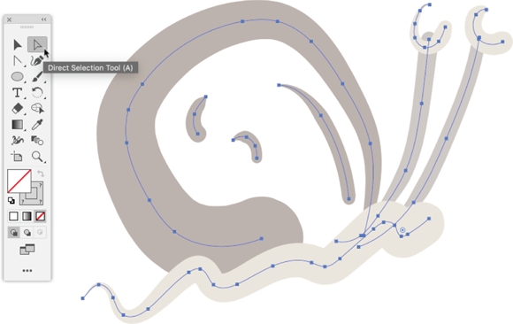
FIGURE 7-2: Exposing anchors by using the Direct Selection tool.

FIGURE 7-3: Selecting an anchor.
To delete a selected anchor, just press Delete. To move a selected anchor, and thus change the shape of a path, click and drag, as shown in Figure 7-4.
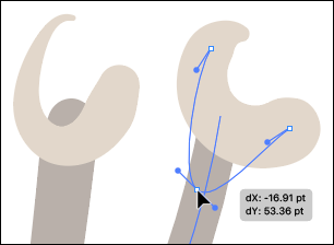
FIGURE 7-4: Moving an anchor.
When you move anchors, you can hold down the Shift key to constrain the movement to increments of 45 degrees.
 Use the Direct selection to move a single anchor or selected anchors when you need to reshape an object. But is not advisable to use the Direct Selection tool to change the location, the size, or the height-to-width aspect ratio of an object. You can do those tasks more easily — and with less chance of inadvertently changing the shape of the object — by using the Selection tool.
Converting open paths to closed paths and vice versa
An open path is one that has a beginning and end, and the beginning and end points are not connected. An ellipse is not an open path. A line segment is an open path.
To connect the beginning and end of an open path, first select the beginning and end anchors with the Direct Selection tool. You can do that by Shift-clicking each anchor, or by using the Direct Selection tool to draw a marquee, as shown in Figure 7-5.

FIGURE 7-5: Selecting the beginning and end anchors.
With the anchors selected, click the Connect Selected End Points icon in the Control or the Properties panel, or choose Object ⇒ Path ⇒ Join from the menu to convert the object into a closed path, as shown in Figure 7-6.
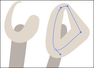
FIGURE 7-6: Closing an open path.
You can also quickly and easily divide an object by cutting a closed path at two selected anchor points. Select the two anchors, and click the Cut Path at Selected Anchor Points tool in the Control or Properties panel. Selecting only one anchor will create an open path.
You can also quickly and easily connect two discrete (not connected) path segments by selecting one anchor in each path, and clicking the Connect Selected Anchor Points icon in the Properties panel or the Control panel, as shown in Figure 7-7.
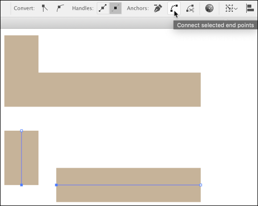
FIGURE 7-7: Connecting anchors from two separate paths to form a single object.
Editing Curves with the Anchor Point Tool
The Anchor Point tool allows you to alter the nature of anchors by moving handles, the tiny circles at the end of thin lines that extend from an curved anchor.
An anchor can be have no, one, or two handles. If an anchor has one or two handles, the position of these handles controls the curvature of the path that is anchored by the selected anchor. I used anchor as a noun and a verb on purpose here to emphasize that anchors are points but also perform an action (defining location) whereas handles adjust a curve.
Illustrator paths can have three kinds of anchor points: corner anchors, smooth anchors, and combination anchors, which connect a curve and a straight line path.
I noted that anchors can have zero, one, or two handles. Here’s how that works: Curved anchors display two handles, tiny lines that control the curves. Combination anchors (which combine a straight angle path and a curved path) display a single handle. Corner anchors do not have active handles. Let’s explore these.
Figure 7-8, left, shows the simplest kind of anchor, a corner point anchor that connects straight line paths.
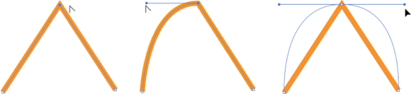
FIGURE 7-8: A corner anchor connecting two straight line segments (left), a combination curved and straight anchor (middle), and a curved anchor (right).
Figure 7-8, middle, shows a combination anchor that is connecting a straight line segment and a curved segment. The combination anchor has one control handle, which is used to control the curve.
Figure 7-8, right, shows a curved anchor with two control handles, one for each curve.
You can use the Anchor Point tool to do the following:
- Add handles to an anchor by clicking the anchor and dragging away from the anchor. You can edit the resulting curve interactively as you move the handles, as shown in Figure 7-9.
- Change an anchor to a combination of a curve and an angle by double-clicking one handle.

FIGURE 7-9: Editing a curved anchor.
- Change an anchor from a curve to an angle by double-clicking the anchor or both handles.
At any time, you can select a handle with the Anchor Point tool and click and drag to change the curvature of the path anchored by the selected anchor. This is the most powerful way to tweak the exact nature of a curved segment. You can also use icons in the Control or Properties panels to convert an anchor to a corner or smooth point.
Drawing with the Pen Tool
Drawing or editing paths by using the Pen tool is unintuitive. But odds are high that you will still need to be able to wield the mighty Pen tool (and the associated Anchor Point tool) to complete most projects.
Why is that? Good question! Here’s an analogy that you might find helpful: Today’s web design platforms, such as WordPress, Wix, or Weebly, are WYSIWYG (what you see is what you get) tools. You don’t need to know HTML (the basic language that defines web page structure) or CSS (the language that styles websites) to create a web page today. You just click and drag to generate boxes into which you enter content such as text, photos, or video. But if you want to customize colors, do some custom layouts, or change to a font of your choice, you need to push the curtain aside and edit the HTML and CSS that was generated by your WYSIWYG design platform. To continue the analogy, you don’t need to design websites with HTML and CSS or even be fluent in creating content with those languages. But you need to be conversant enough with HTML and CSS to make basic edits.
Similarly with the Pen tool. You usually don’t need to use the Pen tool to create an illustration from scratch. But you do need to know how to tweak illustrations by using the Pen tool — and how to deploy the Pen tool as your main design tool when appropriate.
Creating curved, combination, and straight anchors with the Pen tool
The most unintuitive thing about drawing with the Pen tool is that you don’t click and drag to create paths. Instead you click once, and then if you hold down the mouse key after setting the anchor and click and drag, you edit the anchor handles on the fly.
This method is easier done than said, so try using the following steps to use the Pen tool to draw a path that includes curved, combination, and straight anchors:
- Select the Pen tool and click once.
- In the workspace, click and hold down the mouse button, and then drag right (or left), as shown in Figure 7-10, to define the curve of the new anchor. If you hold down the Shift key as you drag to define the curve, you constrain the curve angle to increments of 45 degrees.

FIGURE 7-10: Defining a curve as you draw with the Pen tool.
- In the workspace, define a combination anchor as follows:
- Click with the Pen tool to create a new anchor but do not release the mouse button.
- Drag to define two curve handles.
- Release the mouse button and hover the cursor over the new anchor you created. The cursor changes to the Anchor Point tool, as shown in Figure 7-11.
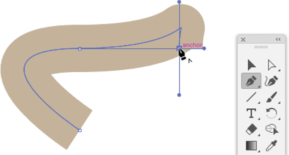
FIGURE 7-11: Preparing to remove one handle to create a combination anchor as you draw with the Pen tool.
- Click to eliminate one of the handles, resulting in a combination anchor.
- Click one last time to create a third anchor. Because the preceding anchor was a combination anchor, the resulting third anchor is a straight angle anchor, as shown in Figure 7-12.
- Press the Esc key to complete the drawing.
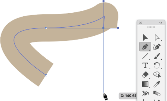
FIGURE 7-12: Adding a straight angle anchor.
Any anchor can be transformed by using the Anchor Point tool.
Adding and deleting anchors
Special Pen tools are available for adding and deleting anchors. They aren’t accessible from the basic toolbar, but they have super-intuitive keyboard shortcuts.
In a previous section, you discover how to delete anchors by using the Direct Selection tool. Another option is to use the Delete Anchor Point tool. The easy keyboard shortcut for this tool is the - (minus sign) key on your keyboard.
With the Delete Anchor tool selected, hover it over a path (regardless of what selection key you used last) until an anchor is displayed, as shown in Figure 7-13.
After you use the Delete Anchor cursor to select an anchor, click to remove the anchor.
With a path selected, moving the Pen tool over an anchor changes the tool to the Delete Anchor Point tool. Moving the Pen tool over a selected path (a section between two anchors) transforms the Pen tool into the Add Anchor Point tool.

FIGURE 7-13: Deleting an anchor by using the Delete Anchor tool.
Here’s another way to add anchors. You can switch to the Add Anchor tool by using the easy-to-remember keyboard shortcut, the + (plus) key. With the Add Anchor tool selected, hover it over any path, as shown in Figure 7-14, and click.

FIGURE 7-14: Adding an anchor by using the Add Anchor tool.
Wielding the Pen tool with shortcuts
The Pen tool is admittedly a bit unwieldy, so it’s nice to have a few handy tips, tricks, and shortcuts at your disposal. Here are some that I think will help you draw and edit paths:
-
To close a path while drawing with the Pen tool, click the first anchor you created.
 A closed path is one with no specific start or end anchor.
 - With the Pen tool selected, hold down the Alt key (Windows) or Option key (Mac) to toggle to the Anchor Point tool. This technique works as long as the Alt or Option key is pressed.
- With the Pen tool selected, you can press the Ctrl key (Windows) or ⌘ key (Mac) to toggle to the Direct Selection tool. This method works as long as the Ctrl or ⌘ key is pressed.
- With the Pen tool selected, you don’t have to switch to the Delete Anchor Point tool or the Direct Selection tool to delete an anchor. If you hover over an existing anchor with the Pen tool, the - (minus) sign appears next to the anchor, and the Pen tool converts temporarily to the Delete Anchor Point tool.
- Before you start creating a new object, tap the Esc key twice to stop drawing with the Pen tool.
Honing Pen tool skills with a waveform
The emphasis in this chapter is on using the Pen tool (and the Anchor Point and Direct Selection tools) to tweak, fine-tune, and finish projects after you've created an illustration by using quicker and easier tools such as shapes, the Pencil tool, or the Curvature tool. But sometimes the simplest workflow is to create graphics directly with the Pen tool.
Here’s one important reason to use the Pen tool from the start, when you can: Paths that you draw with the Pen tool are likely to have fewer anchors and paths, which makes them more rational and easier to edit (because there are fewer anchors to worry about). Minimizing the number of anchors and paths in an illustration also cuts down file size, which is particularly important when you export or save files for digital output.
And there some shapes and drawings are just plain easier to create with the Pen tool. One example is a waveform, as shown in Figure 7-15.
I had to create a batch of waveforms recently for a presentation on compressing digital audio for the web. I’ll spare you the technical details of that specific project, but suffice to say that I needed to draw a lot of different waveforms similar to the one in Figure 7-15.

FIGURE 7-15: A waveform created by using the Pen tool.
I walk you through how to create waveforms here. In the process, you get to develop your chops drawing with the Pen tool. The following steps create a waveform with evenly spaced, uniform curves:
- Define grids, display them, and enable snap to grids with a gridline every 72 pixels and a single subdivision as follows:
- View the Preferences dialog (Edit ⇒ Preferences in Windows, or Illustrator ⇒ Preferences on a Mac).
- Select the Guides & Grid tab.
- Set the Gridline Every value to 72 px and the Subdivisions value to 1, as shown in Figure 7-16, and click OK.
- On the View menu, if Show Grid is not enabled, select it to display gridlines.
- Again on the View menu, if Snap to Grid is not enabled, select that option to force anchors to magnetically snap to the grid.
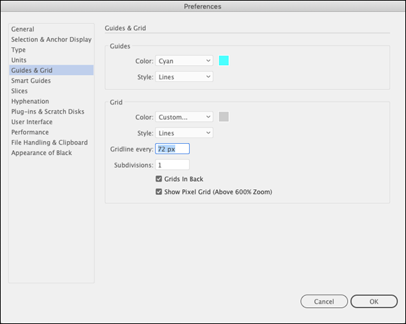
FIGURE 7-16: Defining a wave-friendly grid.
- Select the Pen tool. Then in the Control or Properties panel, select no fill, select a colored stroke (your choice), and then define a 6-pixel stroke, as shown in Figure 7-17.
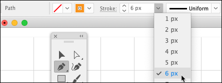
FIGURE 7-17: Setting Pen tool styling in the Control panel.
- Draw the beginning of the first curve 72 px high with a 36 px radius, as follows:
- At any intersection in the grid, click once with the Pen tool but do not release the mouse button.
- Continue to hold down the mouse button and drag the cursor two grid squares up and two grid squares to the right, then click and hold.
- Continue to hold down the mouse button, drag to the right one square, and then release the mouse button. You have just created a curve anchor half the diameter of the wave, as shown in Figure 7-18, left.
- Complete the first wave, as follows:
- Two grid squares to the right of the first anchor and two squares down, click and hold with the Pen tool.
- Still holding down the mouse button, click one square to the right. You have just defined the anchor curve for the second anchor, as shown in Figure 7-18, right.

FIGURE 7-18: Using the Pen tool to draw the first two waves in a waveform.
- Repeat Step 3 and 4 to continue defining the waveform.
-
Repeat Steps 3 and 4 again to complete the waveform, but when you create the last anchor, just click — don’t click and drag. Then press Esc twice to end the path.
The result is shown in Figure 7-19.
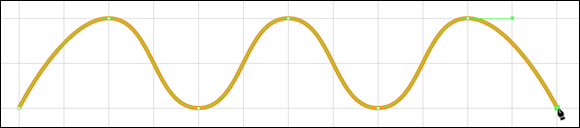
FIGURE 7-19: Completing a waveform by using the Pen tool.
 The steps for drawing the waveform by using the Pen tool involved setting some extreme grid sizes to make it easy to draw precise curves. If you completed those steps, you probably want to revert the screen to normal, smaller grid sizes. You can do that in the Preferences dialog. Select the Guides & Grid tab and set the Subdivisions value to 8.
You can enhance the waveform graphic with a text legend, a gradient background, and some vertical line segments, as I did in Figure 7-15. You learn to create gradients in Chapter 12, artistic text in Chapter 16, and line segments in Chapter 4.
The distinct elements that make up the waveform graphic in Figure 7-15 are revealed in Figure 7-20.
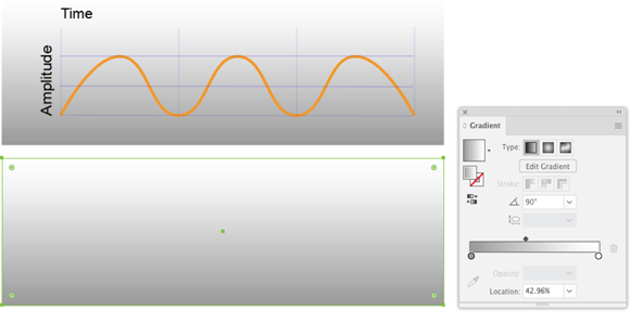
FIGURE 7-20: Adding a legend, a background gradient, and some horizontal and vertical line segments to the illustration.