
Chapter 4
Drawing Lines and Shapes
IN THIS CHAPTER
![]() Designing graphics with basic shapes
Designing graphics with basic shapes
![]() Building complex shapes
Building complex shapes
![]() Creating compound paths
Creating compound paths
![]() Drawing shapes with perspective
Drawing shapes with perspective
![]() Applying isometric effects to shapes
Applying isometric effects to shapes
Compelling graphic designs can be put together by artfully arranging simple shapes. In fact, the very simplicity of shapes makes them so widely applicable and effective.
My mission here is not to unleash a shapes-appreciation movement. I’ll leave that to Picasso and his acolytes. Seriously, take some time to explore and appreciate Picasso’s use of shapes (see, for example, the concise discussion of Cubism at www.pablopicasso.org/ ).
Okay, let’s get here-and-now practical. Contemporary print and digital designers use shapes as the foundation for the following:
- Icons
- Logos
- Symbols
- Print design elements
- Navigation buttons and other elements of app interfaces
- And much more
What do the items in the preceding list have in common? Lots of things, of course, including the fact that every designer needs to be able to create them. But here’s another feature they share: They often are built almost entirely with basic shapes.
And Adobe Illustrator is the ultimate tool for creating, transforming, and combining shapes.
Building Graphics with Basic Shapes
Creatively deploying shapes is a key element of modern aesthetics. And in Adobe Illustrator, drawing, generating, combining, and arranging shapes are core elements in contemporary graphic design for print and screen.
Digital interfaces, such as the app interface prototype in Figure 4-1, are usually built from simple shapes.

FIGURE 4-1: This app interface prototype screen is built almost exclusively with basic shapes.
Play a little “Where’s Waldo” with that figure and see how many basic shapes you can identify. See any ellipses (ovals and circles)? A triangle, or two, or three, or four, or five? A hexagon? Rectangles? Lines (horizontal and vertical, of various thicknesses)? How about stars?
Figure 4-1 demonstrates the use of shapes in digital design, but shapes are also ubiquitous in design for print. Arrangements of shapes like those in Figure 4-2 could be used with a wide array of messages in a poster.
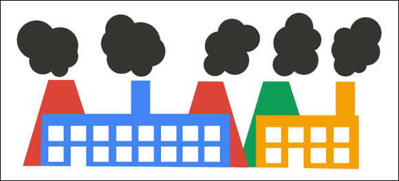
FIGURE 4-2: This graphic is built with just rectangles and ellipses.
In Figure 4-3, I selected all the paths and anchors so you could see how the illustration is composed of only rectangles, trapezoids (truncated triangles with the top chopped off), and ellipses (combined to make the billowing smoke clouds).

FIGURE 4-3: Revealed: rectangles and ellipses.
By now, I expect you’re chomping at the bit to learn not just the basics but more advanced design and workflow techniques to deploy shapes. Even though you’ve been through some basic training in creating shapes, I think you’ll find valuable tips in this lesson.
Let’s dive in then, right?
Generating shapes
The tools you need to create shapes are in the Shapes flyout in the toolbar. And if you’re going to be working with shapes intensively, you’ll likely want to pull those tools off the toolbar for easy access. So let’s do that now.
- Create a new document by choosing File ⇒ New.
- In the dialog that opens, click any of the presets and click the Create button.
- If the toolbars are not visible, choose Window ⇒ Toolbars ⇒ Basic.
- Click the Shape tool until its flyout appears.
- Click in the vertical bar to the right of the tools (it’s dimmed in Figure 4-4).
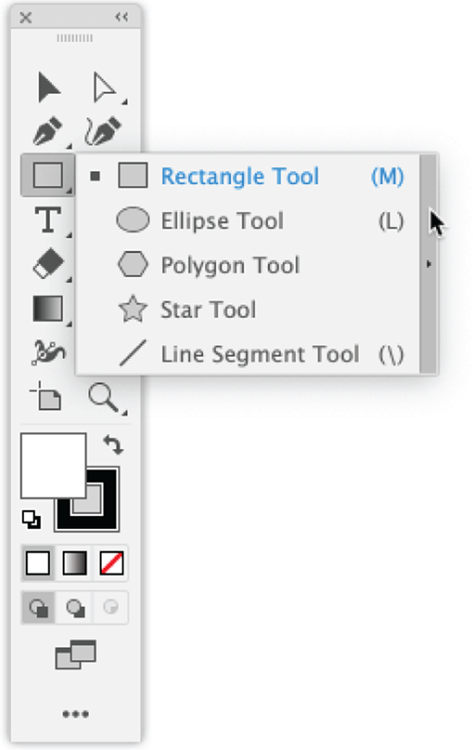
FIGURE 4-4: Pulling the Shape tool’s flyout off the toolbar.
After you pull the Shape tool’s flyout off the toolbar, you can drag that set of tools around your workspace by clicking and dragging any part of the tool set except the tools themselves, as shown in Figure 4-5.

FIGURE 4-5: Moving the shape tools flyout around the workspace.
Clicking to generate shapes
When you have a shape tool selected and click in the workspace, a dialog pops up prompting you to define a shape. This can be confusing because it’s easy to forget that clicking when a shape tool is selected does not launch a process of dragging to draw the shape. Instead, it opens a dialog.
This feature is valuable because you can define a shape with a precise size quickly and accurately instead of futzing around trying to draw the shape on the fly. You know you need a 72-pixel square? Click, enter the values 72 and 72, click OK, and you're done!
So let’s walk through generating shapes with dialogs.
Generating a rectangle
Let me illustrate the point about a dialog popping up when you click in the Illustrator workspace with a shape tool selected. In Figure 4-6, I selected the Rectangle tool, and clicked once in the workspace.

FIGURE 4-6: The Constrain Width and Height Proportions feature is turned off in the Rectangle dialog.
That action did not initiate a process by which I can draw a rectangle. Instead, it triggered the Rectangle dialog you see in Figure 4-6. Here, I can define a rectangle by entering values in the Width and Height boxes.
When you select the Constrain Width and Height Proportions icon to the right of the values, it locks in the height-to-width aspect ratio. So, for example, if you have this feature enabled and change the value of a width, the value of the height will change proportionally. To use a simple example, suppose you have the Constrain Width and Height Proportions feature selected and start with values of 100 px for both the height and the width. If you then change the height to 200 px, the width will change to 200 px as well.
You toggle this width-height constraint feature on and off by clicking its icon, as I’m doing in Figure 4-6.
After you click OK in the Rectangle dialog, Illustrator generates a rectangle whose upper-left corner is at the spot in the workspace where you originally clicked. In Figure 4-7, I used two intersecting guides to identify the origin point — that is, the point where I clicked to begin generating the rectangle. (For instructions in creating guides from rulers, see Chapter 5.)

FIGURE 4-7: Locating a generated rectangle in relation to the insertion point.
The function of that origin point varies depending on what kind of shape you’re generating. For a rectangle, the origin point defines the upper-left corner. For an ellipse, it locates the upper-left corner of the bounding box around the shape, as shown in Figure 4-8.
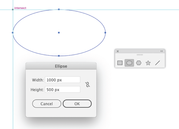
FIGURE 4-8: Locating a generated ellipse.
To round a rectangle digitally, click in the Control panel and then click Shape Properties (in Chapter 2, you find out how to view and access context-dependent features in the Control panel). You do not need to select a specific part of the rectangle first. With the Link Corner Radius Values icon selected (that’s the default), enter a value for any of the four corner radii, as shown in Figure 4-9.

FIGURE 4-9: Rounding a rectangle.
You can control corner radii values also interactively by clicking and dragging. I show you how to do that later in this chapter.
 Another technique for drawing rectangles (and other shapes) is to select the Shaper tool and draw a rough shape. Anything close to a rectangle, a triangle, or an ellipse will be converted automatically into a corresponding shape. Drawing with the Shaper tool is similar to drawing with the Pencil tool. I explore the Pencil tool detail in Chapter 8.
Generating an ellipse
Generating an ellipse (an oval or a circle) is similar to generating a rectangle, but with the following two key differences:
- The basic dialog for ellipses has width, height, and constraint options just like the one for rectangles, but the dimensions define the horizontal and vertical diameters of the ellipse.
- As I noted, an ellipse does not have an upper-right corner. So when you generate an ellipse at a point in the workspace, the upper-right corner of the ellipse’s bounding box aligns with the point where you clicked before generating the shape.
Generating polygons and stars
When you select the Polygon tool, the dialog allows you to define the number of sides for the polygon and the radius, as shown in Figure 4-10. You can generate polygons with an infinite number of shapes, but when that number starts getting high, your shape is more like an ellipse.
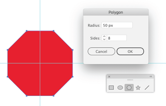
FIGURE 4-10: Defining an octagon.
More likely, you’ll use the Polygon tool for triangles, pentagons, hexagons, and octagons, all of which are used in a wide array of projects ranging from stop signs to app icons.
When you select the Star tool, the dialog allows you to define how many points the star will have, an inner radius (Radius 1), and an outer radius (Radius 2), as shown in Figure 4-11.
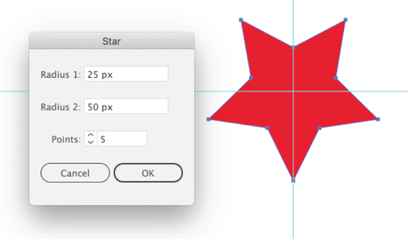
FIGURE 4-11: Defining a five-pointed star, with the outer radius twice the size of the inner radius.
 The dialogs for generating polygons, and the one for stars, locate the generated shapes differently than the dialogs for generating rectangles and ellipses. Instead of placing the generated shape with the bounding box anchored in the upper-left corner with the placement point, Illustrator places ellipses and stars using the selected point as the center of the shape, as you can see in Figures 4-10 and 4-11.
Generating a line segment
To generate a straight line, click the Line Segment tool, and then click in the workspace. The Line Segment Tool Options dialog allows you to define the length of the line and the angle (with the insertion point serving as the fulcrum, or center, that defines that angle, as shown in Figure 4-12).
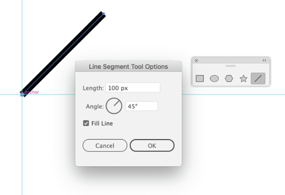
FIGURE 4-12: Generating a line segment.
A few notes about using generated line segments in designs. The segment in the name of this tool is a bit misleading. Don’t use this tool to draw multi-segment paths. For that, use the Pen tool (see Chapter 7). Line segments are for stand-alone lines.
The Fill Line check box in the Line Segment Tool Options dialog doesn’t seem to do much because when you generate a (straight) line segment, there’s no curve to fill. But if you're planning to change the segment to a curve, with a fill applied to the resulting space, you’ll want to select this box. Let me illustrate: If you adjust the curve of the segment, as shown in Figure 4-13, whether or not a fill is generated within the curve depends on how you defined the line segment. (Adjusting curves with the Anchor Point tool is explained in Chapter 7.)
The Stroke panel options are accessed by choosing Window ⇒ Stroke and then choosing Show Options from the panel menu. These options allow you to change the caps at the end of the stroke, make a line dashed, or add arrowheads, and more. The arrowheads and dashed lines are ubiquitous in flowcharts and diagrams, and the ability to style caps is useful in design.
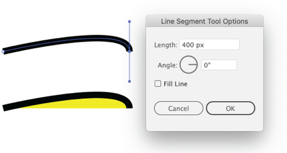
FIGURE 4-13: A line segment, curved without a fill (top) and with a fill (bottom).
In Figure 4-14, I’ve applied butt cap, a round cap, and a projecting cap to the three line segments.
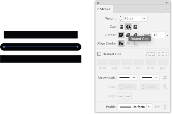
FIGURE 4-14: Applying (top to bottom) a butt, a round, and a projecting cap to a line segment.
Cataloging obscure line and shape tools
Illustrator has a bunch of additional line and shape tools that — with CC — have appropriately been exiled off the Basic toolbar. They’re esoteric (Polar Grid); redundant (Rounded Rectangle, redundant because you can easily round corners on a regular rectangle, as I explain earlier); used occasionally (Arc, Spiral, and Rectangular Grid tools); and inexplicable (Flare).
If you want to experiment with them, click the Edit Toolbar ellipses at the bottom of the toolbar and scroll through to the Draw section.
Drawing shapes interactively
Generating shapes by clicking and defining properties in the Options dialog is often an efficient way to work. You can generate the shapes you need, and then move, copy, and change them to fit your design needs. But at other times, you’ll want the freedom and flexibility of just clicking and dragging to intuitively draw a shape.
Drawing shapes is similar to generating them, except that instead of selecting a shape tool and clicking, you select a shape tool and click and draw. As you do, the dimensions of your shape are displayed, as shown in Figure 4-15.

FIGURE 4-15: Dimensions are displayed when you draw a rectangle.
Following are some tips for drawing shapes:
- To constrain dimensions to squares (for rectangles); circles (for ellipses); and no rotation (for polygons and stars), hold down the Shift key while drawing.
- To draw out from a center point, hold down the Alt key (Windows) or the Option key (Mac). This step is not necessary for polygons and stars because they are always drawn from the center point.
- You can combine these effects by holding down the Shift key and the Alt key (Windows) or Option key (Mac) at the same time.
- To interactively change the number of points on a star or sides on a polygon, use the up arrow (to add) or down arrow (to subtract) keys on your keyboard as you draw.
- Drag clockwise or counterclockwise with your mouse, touchscreen, or drawing pad to rotate as you draw.
Applying Shape Properties from the Control Panel
I walk through the Control panel and how to get your money’s worth out of it in Chapter 2, but here are some specific ways you can use the Control panel to configure shapes. The Control panel adapts itself to the context of the selected shape, so the options are different depending on which shape is selected.
Hovering your cursor over a link in the Control panel displays helpful tips. In Figure 4-16, one of those tips alerts you to the fact that you can access an alternate way to define colors for the selected object by clicking while holding down the Shift key.
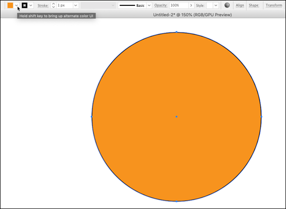
FIGURE 4-16: Exploring shape-friendly options in the Control panel.
Here’s a list of frequently used Control panel links for handy reference when editing shapes:
- The Fill and Stroke boxes open from which you can assign colors. Use the Shift key as you click either of these boxes to open an alternative mode for the color panel, instead of the default swatch panel. The flyout menu, shown in Figure 4-17, allows you to choose from additional color mode options. Here, I’m opting to define colors using RGB values.

FIGURE 4-17: Defining shape colors in RGB.
- The Stroke link opens the Stroke panel, from which you can select stroke weight (thickness), cap, dashed line properties, arrowheads, and profiles (those profiles provide a set of options for strokes of varying thickness).
- The Opacity link allows you to set opacity for both the stroke and fill of a selected shape. See Chapter 12 for details on defining transparency and opacity.
- If you have defined graphic styles, the Style drop-down can be used to apply them to the fill of a selected shape.
- The Shape link provides specific options for different kinds of shapes (and the line segment).
- The Transform link provides quick access to digitally resizing or moving objects, rotation, and shearing. I discuss these features in Chapter 5.
As if Illustrator weren't complicated enough, the Properties panel provides access to a set of features similar to those in the Control panel. My two cents’ worth on the Properties panel? Unless your monitor screen needs additional clutter, you can probably survive without activating this panel.
Reshaping Shapes
In Chapter 5, I dive into transforming any kind of object. There I explain how to use the Scale tool, the Transform panel, and other techniques for large-scale, precise scaling and rotation workflow, including rotating on fixed anchor points.
Some basic, specific techniques common to interactively transforming shapes as you design are worth a quick survey here.
Selecting, moving, and coping shapes
Moving a shape can sometimes be a hassle because you need to avoid selecting an anchor or a path, and instead select the shape itself. Do that by selecting the shape (with the Selection tool), and dragging on the Center icon, shown in Figure 4-18.
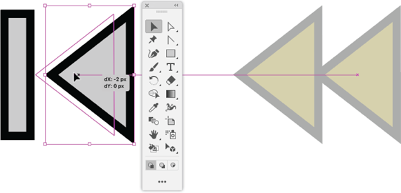
FIGURE 4-18: Moving a shape.
You can select contiguous shapes by using the Select tool, and drawing a marquee (a bounding box) around the shapes you want to transform. With the shapes selected, click and drag any of the center icons to move the selected shapes, as shown in Figure 4-19. This technique works for non-contiguous shapes too; instead of drawing a marquee to select shapes, hold down the Shift key as you select different shapes, and then drag them around the workspace by using any of the center icons.
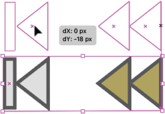
FIGURE 4-19: Moving selected shapes.
Hold down the Shift key as you move a shape or selected shapes to lock the movement into horizontal or vertical alignment, or to constrain the angle of rotation to 45 degrees.
Hold down the Alt key (Windows) or the Option key (Mac) as you move selected shapes to copy them as you move them, as shown in Figure 4-20.

FIGURE 4-20: Copying selected shapes.
Selecting and moving shape anchors and paths
You can reshape a shape (redundant as that might sound) by selecting a path with the Direct Selection tool, and then moving that path, as shown in Figure 4-21. Holding down the Shift key as you drag a path constrains the angle you can drag, which helps maintain the integrity of the shape.

FIGURE 4-21: Editing a shape path with the Direct Selection tool.
You can also use the Direct Selection tool to select and move anchors, and thus resize and reshape shapes, as shown in Figure 4-22. Here, too, holding down the Shift key as you move an anchor constrains the move to fixed angles.

FIGURE 4-22: Editing an anchor location with the Direct Selection tool.
You can also use Shift-Click to select more than one anchor, or path, and move them all together.
Interactively rescaling shapes
You can change the size of a shape or selected set of shapes by clicking and dragging an anchor. Hold down the Shift key as you resize the shape or selected shapes to maintain the height-to-width aspect ratio, as shown in Figure 4-23. Note that both the original shape sizes and the new shape size are displayed, with the new size outlined in blue.
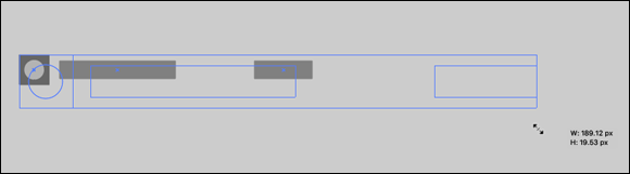
FIGURE 4-23: Resizing selected shapes while maintaining the height-to-width ratio.
If you click and drag corner anchors, you can interactively resize both the height and width of a shape or a selection of shapes. If you click and drag a side handle, you can resize either the height or the width (unless you are holding down the Shift key, in which case the height-to-width aspect ratio is locked).
If you hold down the Alt key (Windows) or Option key (Mac) while you resize a shape or shapes, the center point stays locked in position, as shown in Figure 4-24.

FIGURE 4-24: Interactively resizing a circle and two line segments while maintaining the center point.
Interactively rotating shapes
You can easily and interactively rotate a selected shape. To do so, you need to display the bounding box (the rectangle that encloses the shape). If the bounding box is not visible, choose View ⇒ Show Bounding Box.
To rotate a selected shape interactively in the workspace, hover your cursor over one of the corner or side boxes in the bounding box with the Selection tool (not the Direct Selection tool) until the rotation icon appears, as shown in Figure 4-25. Click and drag clockwise or counterclockwise to rotate the selected shape or shapes.
With Smart Guides on, Illustrator displays the rotation angle as you rotate. Holding down the Shift key constrains the rotation to increments of 45 degrees. Smart Guides are enabled by default, and I explain how to change settings in Chapter 1.

FIGURE 4-25: Interactively rotating selected shapes.
Interactively rounding rectangles
Before rounding out my Top Five list of interactive reshaping techniques for shapes (yup, it’s five, count ’em), let me show you a quick, easy interactive way to round rectangles. In today’s world of digital design, rounded rectangles are more likely to be referred to as buttons with border radii, but it’s all the same thing.
I noted earlier, in surveying shape tools that you won’t use, that the Rounded Rectangle tool (still available from the full set of tools) isn’t necessary. That’s because it’s so easy to add a corner radius to regular rectangles. Earlier in the chapter I showed you how to define a corner radius with the Shape properties link in the Control panel, but you can also do it interactively.
So, after all that buildup, here’s how to round corners (or define border radii): With the Direct Selection tool, hover your cursor over any corner of a selected rectangle and view the curve icon that appears. Drag the icon, as shown in Figure 4-26, to interactively create a border radius.

FIGURE 4-26: Defining a border radius interactively.
If you want to define the border radius for just one corner of a rectangle, select a corner anchor with the Direct Selection tool. Only one round corner icon will appear.
Building Complex Shapes
Shapes are infinitely editable when you use the Direct Selection tool to click and drag anchors, or delete anchors. I walk you through using the Direct Selection tool in Chapter 5. For now, here's a basic example. To convert a circle to a semicircle, you select one of the anchors, as shown in Figure 4-27, and delete that anchor by simply pressing the Delete key.
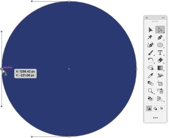
FIGURE 4-27: Selecting an anchor in a circle.
The result is the semicircle shown in Figure 4-28.
So that’s shape-editing 101, and again, I walk through how to edit paths of every kind, including shapes, with selection tools in Chapter 5. But Illustrator also comes with a very powerful set of tools for combining shapes in all kinds of ways.
Creating a compound path
Because Illustrator shapes are discrete objects, knocking out part of one shape with another shape isn’t quite as simple as you might think. For example, to get the effect of looking through narrow windows at trees, shown in Figure 4-29, I couldn’t just draw windows in the gray wall. I had to draw the windows, and then generate a compound path.
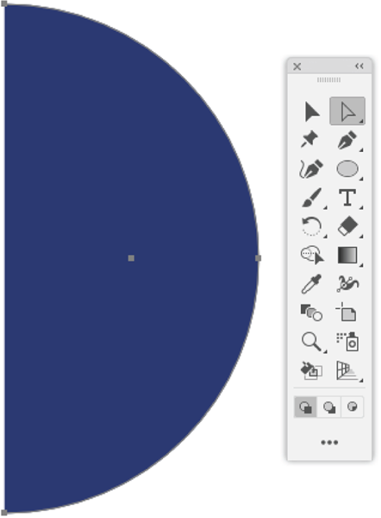
FIGURE 4-28: Creating a semicircle by deleting an anchor.
To create a compound path from overlapping objects, follow these steps:

FIGURE 4-29: A compound path was used to let the trees be visible through slats in the wall.
-
Select the object(s) to be transformed into a compound path.
For example, in Figure 4-30, I selected the gray rectangle and the white rectangles.
- Choose Object ⇒ Compound Path ⇒ Make to knock out the windows, as shown in the example in Figure 4-31.
-
Size, move, or transform the resulting object.
The resulting compound path can be transformed as a discrete object, as shown in Figure 4-32.
Using Pathfinder to combine shapes
Basically, anything you want to do to combine all or part of overlapping objects can be done with the set of tools in the Pathfinder panel or Pathfinder effects. To take a few widely applied examples:
- You can combine shapes into a single shape (using the Unite icon).
- You can knock out the area(s) where they intersect and create a new shape from the intersected region (using the Intersect icon).
- You can make the areas where they do — and don’t — intersect into distinct objects (using the Divide icon).
I mentioned two options: the Pathfinder panel and the Pathfinder effects. The former is a set of tools in a panel, and the latter are options from the Effects menu. The set of options available in the Pathfinder effects menu and those available in the Pathfinder tools panel are similar, but the two options are used differently.

FIGURE 4-30: Selecting a set of objects to combine into a compound path.
Pathfinder effects have the advantage of being effects. You can select and edit the original (uncombined) objects. And you can use the Appearance panel to modify or remove Pathfinder effects just like you can modify or remove other effects that you apply from the Effects menu. I discuss Pathfinder effects more in Chapter 14.

FIGURE 4-31: Applying a compound path to selected objects.
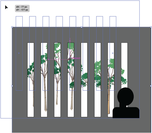
FIGURE 4-32: Moving a compound path.
The big downer, as Jeff Spicoli might put it, with Pathfinder effects from the Effects menu is that they can’t be applied to individual shapes. Huh? What good is a set of effects that can’t be applied to shapes? Well, Pathfinder effects can be applied to grouped shapes, text objects, or layers. But the inability to apply them to selected shapes drastically limits their usefulness in many design situations. Figure 4-33 shows what happens, for example, if I try to apply the Exclude effect from the menu to two selected objects.

FIGURE 4-33: Attempting to apply a Pathfinder effect from the menu to two overlapping shapes.
By contrast, when I apply the Exclude effect from the Pathfinder panel to the same two selected objects, I get the result shown in Figure 4-34.
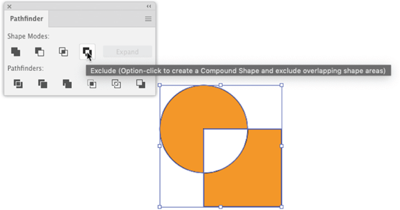
FIGURE 4-34: Applying the same Pathfinder effect from the Pathfinder panel.
Although there are times and places to use Pathfinder effects from the menu, in the interests of avoiding semi-redundancy, and because the objects to which you can apply Pathfinder effects from the Effects menu are so limited, I focus here on applying them from the panel.
It’s easier to show how Pathfinder tools work than to try to describe them, so I’ve put together a set of images in Figure 4-35 that demonstrate the panoply of effects you can generate from the Pathfinder tools when two objects are selected.

FIGURE 4-35: The effects of Pathfinder panel tools on two overlapping objects.
The four icons in the top row of the Pathfinder panel create paths or compound paths. The bottom row generates new shapes from the overlapping or intersecting parts of the objects.
Note that Figure 4-35 displays the anchors and paths generated by these tools. Why? Because sometimes the unselected objects look alike, but their underlying path structures (and thus what you can do with the result) differ.
For example, the result of applying the Unite tool (second row, first column in Figure 4-35) looks like the result of applying the Divide tool (third row, first column). But you can see that the resulting anchors and paths are different: You can pull apart the objects that resulted from the Divide tool, but you cannot pull apart formerly distinct shapes after you combine them with the Unite tool.
Figure 4-35 illustrates all the Pathfinder panel tools:
- Row 1 is the original set of two overlapping objects. Note that the magenta circle is in front of the orange square. You’ll want to keep that in mind as you explore the effect of different Pathfinder tools.
- Row 2 demonstrates the effect of the Unite, Minus Front, Intersect, and Exclude tools without holding down the Alt key (Windows) or Option key (Mac).
- Row 3 demonstrates the effect of the Unite, Minus Front, Intersect, and Exclude tools while holding down the Alt key (Windows) or Option key (Mac).
- Row 4 demonstrates the effect of the Divide, Trim, Merge, Crop, Outline, and Minus Back tools.
Yet another approach to combining shapes is to use the Shape Builder tool. I explain how that works in Chapter 8.
Drawing Shapes with Perspective
Every art student is taught how to draw with perspective — that is, setting one or two vanishing points and having objects recede in size as they approach that vanishing point. Illustrator provides the Perspective Grid to facilitate drawing with vanishing points. Since it was introduced in Illustrator CS5, it has been a feature that — as Mick Jagger says about the Stones’ “Their Satanic Majesties Request” — has received “mixed reviews.”
But I’m going to expose you to a quick look at Perspective Grid. Why? Because when you find the right time and place to deploy the Perspective Grid, it’s a powerful productivity tool for prototyping architectural renderings and other 3D projects.
I’ll demonstrate how the Perspective Grid and Perspective Grid Selection tools work to create a standard two-dimensional grid.
- Before you begin to draw, choose View ⇒ Perspective Grid ⇒ Two Point Perspective ⇒ [2p-Normal View], as shown in Figure 4-36.
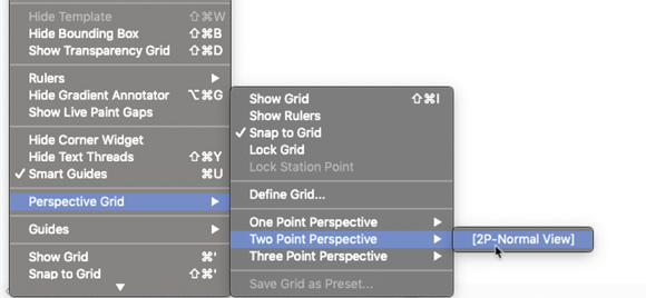
FIGURE 4-36: Defining a Perspective Grid.
- In the All Tools section of the toolbar, drag the Perspective Grid tool and the Perspective Selection tool into the toolbar, as shown in Figure 4-37.
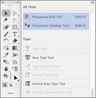
FIGURE 4-37: Accessing the Perspective Grid tool and Perspective Selection tool.
- With the Perspective Grid tool selected, adjust the horizontal and vertical vanishing points, as shown in Figure 4-38.
-
Use the Active Plane Widget to select a plane to edit, as shown in Figure 4-39.
The widget appears by default in the upper-left corner of your workspace.

FIGURE 4-38: Adjusting the vanishing points.
- With the grid defined and the pane selected, draw a rectangle on the active plane, as shown in Figure 4-40.
- Use the Perspective Grid Selection tool to edit the rectangle, as shown in Figure 4-41.

FIGURE 4-39: Selecting a pane to edit.
I think you can take it from here, adding and tweaking rectangles. A few tips:
- Define fill and stroke properties as you would for any shape not on the Perspective Grid.
- If you are creating shapes outside the grid, use the Perspective Grid Selection tool to re-access the grid environment.
- You can switch between defined planes at any time by using the Active Plane Widget.
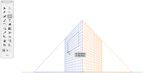
FIGURE 4-40: Drawing a rectangle on the Perspective Grid.
- If you are an experienced 3-D drafter, use the Define Perspective Grid options dialog to customize and fine-tune the perspective type, angles, and horizon height. Access the dialog by choosing View ⇒ Perspective Grid ⇒ Define Grid.
- You can also customize the display of the grid colors and opacity in the Define Perspective Grid dialog.

FIGURE 4-41: Editing a shape in the Perspective Grid.
-
 If you move or edit drawn objects in the Perspective Grid by using the regular Selection or Direct Selection tools, instead of the Perspective Grid Selection tool, you’ll lose the snap-to-grid features.
Applying Isometric Effects to Shapes
Isometric effects are a way of applying 3D to shapes, but without the vanishing points that we saw with the Perspective Grid. The drafting table in Figure 4-42 is a fun example of applying isometric effects to shapes.
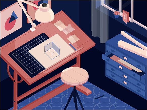
FIGURE 4-42: An illustration composed of isometric shapes.
Many techniques and tricks for drawing isometric shapes are available. If you search online, you’ll find tutorials for creating them by using special grids (laid out diagonally), breaking up hexagons into isometric shapes, and other approaches.
I’ll show you what I think is the quickest and easiest way to create isometric shapes. It is the technique used to create most of the shapes in Figure 4-42.
-
Start with a rectangle.
I won’t rehash how to do that; jump to the beginning of the chapter if you need some help.
-
With the rectangle selected, choose Effect ⇒ 3D ⇒ Extrude & Bevel.
The 3D Extrude & Bevel Options dialog opens. Many features are here, accessible from the Map Art and More Options buttons. For an exploration of those options, see Chapter 14. We don’t need those options to generate isometric shapes.
-
In the Position drop-down in the dialog, choose one of the four isometric options, and then click Preview to see how that effect will transform your rectangle.
In Figure 4-43, I’m previewing Isometric Right.

FIGURE 4-43: Previewing an isometric effect on a rectangle.
- Experiment with options:
- Extrude Depth changes the third dimension in your isometric shape.
- The two Cap options toggle between a filled in shape and hollow isometric shape.
- Bevels add a range of effects that you can experiment with by using the Preview option.
-
After you define the isometric shape, click OK to generate it.
You can scale, rotate, and in other ways transform the generated isometric shape. If you want to convert the effect to a set of shapes, choose Object ⇒ Expand Appearance.
The image you come out of these steps with can be edited like any set of shapes. Rotate it. Resize it. Move it. Make copies of it, and put the resulting shapes together to form more complex sets of isometric shapes. Or edit the paths, as shown in Figure 4-44.

FIGURE 4-44: Editing an effect expanded as isometric shapes.