1
Introduction
This chapter outlines briefly the historical development, emergence, and merging of the fundamental digital communication and optical communication techniques to fully exploit and respond to the challenges of the availability of ultra-high frequency and ultra-wideband in the optical spectra of optical fiber communications technology. The organization of rest of the chapters of the book is outlined in this chapter.
1.1 Digital Optical Communications and Transmission Systems: Challenging Issues
Starting from the proposed dielectric waveguides by Kao and Hockham [1,2] in 1966, the first research phase attracted intensive interest around the early 1970s in the demonstration of fiber optics, and optical communications has greatly progressed over the past three decades. The first-generation lightwave systems were commercially deployed in 1983 and operated in the first wavelength window of 800 nm over multimode optical fiber (MMF) at transmission bit rates of up to 45 Mbps [1, 2 and 3]. After the introduction of ITU-G652 standard single-mode fiber (SSMF) in the late 1970s [3,4], the second generation of lightwave transmission systems became available in the early 1980s [5,6]. The operating wavelengths were shifted to the second window of 1300 nm, which offers much lower attenuation for silica-based optical fiber as compared to the previous 800 nm region. In particular the chromatic dispersion (CD) factor is close zero. This spectral window is current attracting lots of interests for optical interconnections for data centers. These second-generation systems could operate at bit rates of up to 1.7 Gbps and have a repeaterless transmission distance of about 50 km [7]. Further research and engineering efforts were also devoted to the improvement of the receiver sensitivity by coherent detection techniques, and the repeaterless distance reached 60 km in installed systems with a bit rate of 2.5 Gbps. Optical fiber communications then evolved to third-generation transmission systems that utilized the lowest-attenuation 1550 nm wavelength window and operated up to a bit rate of 2.5 Gbps [7,8]. These systems were commercially available in 1990 with a repeater spacing of around 60–70 km [7,9]. At this stage, the generation of optical signals was based on direct modulation of the semiconductor laser source and either direct detection. Since the invention of erbium-doped fiber amplifiers (EDFAs) in the early 1990s [10, 11 and 12], lightwave systems have rapidly evolved to wavelength division multiplexing (WDM) and shortly after that to dense WDM (DWDM) optically amplified transmission systems that are capable of transmitting multiple 10 Gbps channels. This is because the loss is no longer a major issue for external optical modulators, which normally suffer an insertion loss of at least 3 dB. These modulators allow the preservation of the narrow linewidth of distributed feedback lasers (DFBs). These high-speed and high-capacity systems extensively exploited the external modulation in their optical transmitters. The present optical transmission systems are considered as the fifth generation, having a transmission capacity of a few terabits per second [7].
Coherent detection, homodyne or heterodyne, was the focus of extensive research and development during the 1980s and early 1990s [13, 14, 15, 16, 17 and 18] and was the main detection technique used in the first three generations of lightwave transmission systems. At that time, the main motivation for the development of coherent optical systems was to improve the receiver sensitivity, commonly by 3-6 dB [14,17]. Thus, the repeaterless transmission distance could be extended to more than 60 km of SSMF (with a 0.2 dB/km attenuation factor). However, coherent optical systems suffer severe performance degradation due to fiber dispersion impairments. In addition, the phase coherence for lightwave carriers of the laser source and the local laser oscillator were very difficult to maintain. On the contrary, the incoherent detection technique minimizes the linewidth obstacles of the laser source as well as the local laser oscillator, and thus relaxes the requirement of the phase coherence. Moreover, incoherent detection mitigates the problem of polarization control in the mixing of transmitted lightwaves and the local laser oscillator in the multiterahertz optical frequency range. The invention of EDFAs, which are capable of producing optical gains of 20 dB and above, has also greatly contributed to the progress of incoherent digital photonic transmission systems up to now.
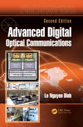
Recent years have witnessed a huge increase in demand for broadband communications driven mainly by the rapid growth of multimedia services, peer-to-peer networks, and IP streaming services, in particular IP TV. It is most likely that such tremendous growth will continue in the coming years. This is the main driving force for local and global telecommunications service carriers to develop high-performance and high-capacity next-generation optical networks. The overall capacity of WDM or DWDM optical systems can be boosted either by increasing the base transmission bit rate of each optical channel, multiplexing more channels in a DWDM system or, preferably, by combining both of these schemes. However, while implementing these schemes, optical transmission systems encounter a number of challenging issues, which are outlined in the following paragraphs Figure 1.1.
Current 10 Gbps transmission systems employ intensity modulation (IM), also known as on–off keying (OOK), and utilize non-return-to-zero (NRZ) pulse shapes. The term OOK can also be used interchangeably with amplitude shift keying (ASK) [1,2].* For high-bit-rate transmission such as 40 Gbps, the performance of OOK photonic transmission systems is severely degraded owing to fiber impairments, including fiber dispersion and fiber nonlinearities. The fiber dispersion is classified as CD and polarization-mode dispersion (PMD), causing the intersymbol interference (ISI) problem. On the contrary, severe deterioration in the system performance due to fiber nonlinearities result from high-power spectral components at the carrier and signal frequencies of OOK-modulated optical signals. It is also of concern that existing transmission networks comprise millions of kilometers of SSMF, which have been installed for approximately two decades. These fibers do not have as advanced properties as the state-of-the-art fibers used in recent laboratory “hero” experiments, and they have degraded after many years of use.
The total transmission capacity can be enhanced by increasing the number of multiplexed DWDM optical channels. This can be carried out by reducing the frequency spacing between these optical channels, for example, from 100 GHz down to 50 GHz, or even 25 GHz and 12.5 GHz [19,20]. The reduction in the channel spacing also results in narrower bandwidths for the optical multiplexers (mux) and demultiplexers (demux). On passing through these narrowband optical filters, signal waveforms are distorted and optical channels suffer the problem of interchannel crosstalk. The narrowband filtering problems are becoming more severe at high data bit rates, for example, 40 Gbps, thus degrading the system performance significantly.
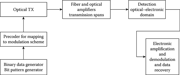
FIGURE 1.1 Schematic diagram of the modulation and the electronic detection and demodulation of an advanced modulation format optical communications system.
Together with the demand for boosting the total system capacity, another challenge for the service carriers is to find cost-effective solutions for the upgrading process. These cost-effective solutions should require minimum renovation of the existing photonic and electronic subsystems; that is, the upgrading should only take place at the transmitter and receiver ends of an optical transmission link. Another possible cost-effective solution is to extend significantly the uncompensated reach of optical transmission links, that is, without using dispersion compensation fibers (DCFs), thus considerably reducing the number of required in-line EDFAs. This network configuration has recently attracted the interest of both the photonic research community as well as service carriers.
Over the past few years, extensive research and development has proved that coherent reception incorporating digital signal processing (DSP) can push the bit rates per wavelength channel to 100 Gbps by employing 25 GBaud polarization multiplexing and QPSK (two bits/symbol) and/ or M-ary quadrature amplitude modulation (M-QAM) to aggregate to 200 Gbps or 400 Gbps. Furthermore, the channels can be made pulse shaped by using digital-to-analog converter (DAC) to pack the channels into superchannels to generate terabits per second (Tbps) per channel with subcarriers. The advances of ultra-high sampling rate analog-to-digital converters (ADCs) and DACs at 64 GSa/s allow the DSP to recover the clock, and hence the sampling rate and time, combating the linear and nonlinear impairments due to CD, PMD, self-phase modulation (SPM), cross-phase modulation (XPM), and other effects. The transmission for 100 Gbps would reach 3500 km in field trials and 1750 km for 200 Gbps over optically amplified and non-DCF fiber span transmission distances.
Therefore, the principal motivations of this book are to describe the employment of digital communications in modern optical communications. The fundamental principles of digital communications, both coherent and incoherent transmission and detection techniques, are described with a focus on the technological developments and limitations of the optical domain. The enabling technologies, research results, and demonstrations on laboratory experimental platforms for the development of high-performance and high-capacity next-generation optical transmission systems impose significant challenges for the engineering of optical transmission systems in the near future and techniques for network monitoring.
1.2 Enabling Technologies
1.2.1 Modulation Formats and Optical Signal Generation
Modulation is the process of facilitating the transfer of information over a medium. In optical communications, the process of converting information so that it can be successfully sent through the optical fiber is called optical modulation.
There are three basic types of digital modulation techniques: amplitude shift keying (ASK), frequency shift keying (FSK), and phase shift keying (PSK), in which the parameter that is varied is the amplitude, frequency, or phase, respectively, of the carrier to represent the information to be sent. Digital modulation is the process of mapping such that the digital data of “1” and “0” or symbols of “1” and “0” are converted into some aspects of the carrier such as the amplitude, the phase, or both amplitude and phase, and then transmitting the modulated carrier, which is the lightwaves in the context of this book. The modulated and transmitted lightwave carrier is then remapped at the reception systems back to a near copy of the information data.
1.2.1.1 Binary Level
Modulation is a process that facilitates the transport of information over the medium; in this book, our medium is the optical-guided fiber and associate photonic components. In digital communications, there are three basic types of digital modulation techniques: ASK, PSK, and FSK. Under these modulation techniques, the phases or amplitudes or frequencies of the lightwaves are varied to represent the information bits “1” and “0”.
In ASK, the amplitude of the lightwave carrier, normally generated by a narrow-linewidth laser source, is changed in response to the digital data, keeping everything else fixed. That is, bit 1 is transmitted by the lightwave carrier of a particular amplitude. To transmit 0, the amplitude is changed keeping the frequency unchanged, as shown in Figure 1.2. NRZ or RZ can be assigned depending on the occupation of the state 1 during the time length of a bit period. For RZ, normally only half of the bit period is occupied by the digital data.
In addition to NRZ and RZ formats, in optical communications, the carrier can be suppressed under these formats so as to achieve non-return-to-zero carrier suppression (NRZ-CS) and return-to-zero carrier suppression (RZ-CS). This is normally generated by biasing the optical modulator in such a way that the carriers passing through the two parallel paths of an interferometric modulator have a π phase shift difference with each other. Thus, the carrier at the center frequency is suppressed, but the sidebands of the modulated signals remain unchanged.
In PSK, the phase of the lightwave carrier is changed to represent the information. The phase in this context is the shift of the angle at the phasor vector initial position at which the sinusoidal carrier starts. To transmit a 0, the phase would be shifted by π and a 1 with no change of phase. The phase angle can be changed and take a value of a set of phases corresponding to the mapping of the symbols as shown in Figure 1.3.
In FSK, the frequency of the carrier represents the digital information. One particular frequency is assigned to 1, and another frequency is assigned to 0, as shown in Figure 1.4. FSK can be considered as continuous phase modulation, for example, a continuous phase modulation MSK (minimum shift keying) whose frequency separation fd is selected such that the signals carried by these frequencies are orthogonal.

FIGURE 1.2 (a) NRZ and RZ pulse amplitude-modulation formats for a sequence of {1 0 1 0 1 0 1 0 1 0 1 0} and (b) generated ASK signals with carrier (not to scale and high-density area) data and carrier-modulated NRZ and NZ formats.

FIGURE 1.3 Signal-space constellation of discrete PM: (a) binary PSK, (b) quadrature binary PSK, (c) eight PSK and (d) phase of the carrier under modulation with π phase shift of the BPSK at the edge of the pulse period.

FIGURE 1.4 Schematic diagram of a FSK transmitter. fd is the deviation frequency from the carrier frequency fc.
ASK can be combined with PSK to create a hybrid modulation scheme such as QAM, where both the phase and amplitude of the carrier are changed at the same time. The carriers are expected to follow a similar pattern as that of differential phase shift keying (DPSK) in Figure 1.3d but with different frequencies of the carrier under the envelope of the bits 0 and 1. For MSK signals, the carrier frequency is chirped up or down depending on the 0 or 1, that is, the phase of the carrier is continuously varied during the bit period, and the carrier frequencies of the bits are such that there is an orthogonality of the carriers and the signal envelope.
1.2.1.2 Binary and Multilevel
An additional degree of freedom for detection can be used to effectively enhance the capacity owing to the effective equivalence of the multilevel and symbol rates, and hence the detection of the received optical signals. A widely used and mature detection scheme for optical signals is the direct detection scheme in which the optical power P = [E]2, the square of a complex optical field amplitude. The photodetector would not be able to distinguish between a 0 or π phase shift of the carrier lightwave embedded within the pulse. The carrier phase can only be possibly extracted if and only if photonic processing to extract the phase at the front end of the receiver is performed. Thus, a + or − field complexity would be seen as identical in the photodetector.

FIGURE 1.5 Illustration of pseudo-multilevel or polybinary baseband signals. Binary data sequence, weighted signals, diphase RZ, and alternate mark inversion formats.
This ambiguity of the phase detection process would allow one to shape the optical spectra of optical signals, thus creating a modulation format more resilient to the distortion effects accumulated during the transmission process.
Formats making use of the tri-level are illustrated in Figure 1.5 and could be termed as pseudo-multilevel, tri-level, or polybinary signals. These tri-level signals can be represented in terms of the phase or frequency of the lightwave carrier.
The use of more than two symbols to encode a single bit of information is to increase the information bits carried by a symbol. However, the transmission is still at the symbol rate Bs. Under optical transmission, the −1 and +1 can be coded in terms of the variation in the phase of the carrier as there is no negative intensity representation unless the field of the lightwaves is used. The tri-level uses {+|E|, −|E|, and 0}, and its equivalent phase representation can be mapped to {0, |E|2} at the optical receiver, for example, the duobinary format, which will be described in a later chapter. A phase difference of π and 0 between the three levels would minimize the pulse dispersion as they are propagating along the fiber with a relative phase difference of π, thus resulting in destructive interference of any pulse spreading due to dispersion.
This tri-level must not be mixed up with the truly multilevel signaling in which log2M bits are encoded on N symbols, and then transmitted at a reduced rate Bs/log2N. Both multilevel amplitude or APSK and DQPSK are multilevel optical modulation techniques. The multilevel modulation formats will be described in Chapter 7.
1.2.1.3 In-Phase and Quadrature-Phase Channels
Another form of modulation that would enhance the capacity of the transmission is the use of the orthogonal channels, in which the information can be coded into the in-phase and quadrature (I–Q) components in polar or Cartesian coordinates, as shown in Figure 1.6.
QPSK is most commonly used in differential and nondifferential phase modulation, in which I and Q components are used extensively owing to its bit error rate (BER); its corresponding energy per bit is similar to that of PSK, doubling the capacity of that of PSK. QPSK is an extension of the binary PSK signals but with a phase change of only π/2 instead of π. Mathematically, the signal s(t) can be expressed as
where ps(t) is the pulse shaping of the data, M is the quantized level or the total number of phase states of the modulation, and πi is the phase modulation index. QPSK can be combined with ASK to generate QAM, where the phase and amplitude can be used to map a symbol of data information into one of the points on the signal space.
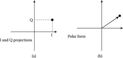
FIGURE 1.6 Signal vectors plotted in signal space: (a) Cartesian coordinates and (b) polar form.
1.2.1.4 External Optical Modulation
External modulation is the essential technique for modulating the lightwaves so that its linewidth preserves its narrowness, and only the sidebands of the modulation scheme dominate the spectral property of the generated passband characteristics. Figures 1.7 and 1.8 show the typical structure of optical transmitters for the generation of NRZ and RZ optical signals.
The laser is always switched on, and its lightwaves are modulated via the electro-optic modulator using the principles of interferometric constructive and destructive interference to represent the ON and OFF states of the lightwaves. The RZ can then be similarly generated but with an additional optical modulator that would generate periodic optical pulses whose width is half of that of the bit period. The phase and frequency modulation can also be generated using these electro-optic modulators by biasing conditions and controlling the amplitudes of the electrical pulses. These optical transmitters are described in Chapter 2. We note here that the fiber that connects the two modulators of Figure 1.8 must be of the polarization maintaining (PM) type. Otherwise, there would be polarization fluctuation and hence reduction in the coupling of the lightwave power to each other.
The laser source would normally be a narrow-linewidth laser that is turned on at all times to preserve its narrowness characteristics. The lightwaves are generated and coupled to the optical modulator via the pigtails of both devices. The modulator is driven with data pulse sequence which is the output of a bit pattern generator (BPG) whose voltage level is conditioned to the appropriate driving level required by the Vπ value of the modulator. The phase variation of the carrier can be similarly implemented for phase modulation. When a modulation format is necessary, then an electronic precoder is required to code the serial sequence for appropriate coding. The precoder can be a differential coding, multilevel coding, or IFFT to generate orthogonal data subchannels in case of orthogonal frequency division multiplexing (OFDM).
The pulses of all modulation formats can take the form of NRZ or RZ. For the RZ format, an additional optical modulator is required to generate or condition the 1 NRZ to RZ, as shown in Figure 1.8. The second modulator can exchange its position with that of the other modulator without affecting the generation of the modulation formats. This second modulator is usually called the pulse carver.
Note that if the RZ modulator is biased such that the phase difference at the biasing condition is π, then we would have carrier suppression located at the central location of the spectra. The sidebands of the optical signals remain unchanged. The bandwidth of the modulator determines the rise time and fall time of the edges of the pulse sequence shown in Figures 1.7 and 1.8. The details of the optical transmitters for different modulation formats are given in Chapter 3.

FIGURE 1.7 Generation of optical signals of format NRZ using an external modulator.
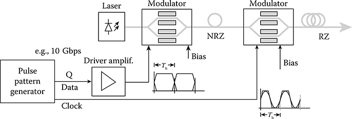
FIGURE 1.8 Generation of optical signals of format RZ.
1.2.2 Advanced Moduíation Formats
The aforementioned problems facing contemporary optical fiber communications can be effectively overcome by utilizing spectrally efficient transmission schemes via the implementation of advanced modulation formats. A number of modulation formats have recently been reported as alternatives for the OOK format, including RZ pulses in OOK/ASK systems [21, 22 and 23], DPSK [19,21, 22, 23, 24, 25 and 26], and more recently, MSK [27, 28, 29, 30, 31, 32, 33 and 34]. These formats are adopted into photonic communications from a knowledge of wireline and wireless communications.
DPSK has received much attention over the last few years, particularly when it is combined with RZ pulses. The main advantages of RZ-DPSK are (1) a 3 dB improvement in the receiver sensitivity over the OOK format by using an optical balanced receiver [22,35,36] and (2) high resilience to fiber nonlinearities [7,21,35,37] such as intrachannel SPM and interchannel XPM. Several experimental demonstrations of DPSK long-haul DWDM transmission systems for 10 Gbps, 40 Gbps, and higher bit rates have been reported recently [19,24,38, 39 and 40]. However, there are few practical experiments addressing the performance of cost-effective 40 Gbps DPSK-10 Gbps OOK hybrid systems for gradually upgrading the existing installed SSMF transmission infrastructure [41,42]. In addition, the performance of 40 Gbps DPSK for use in this hybrid transmission scheme has not been thoroughly studied.
The MSK format offers a spectrally efficient modulation scheme compared to the DPSK counterpart at the same bit rate. As a subset of continuous phase frequency shift keying (CPFSK), MSK possesses spectrally efficient attributes of the CPFSK family. The frequency deviation of MSK is equal to a quarter of the bit rate, and this frequency deviation is also the minimum spacing to maintain the orthogonality between two FSK-modulated frequencies. On the contrary, MSK can also be considered as a particular case of offset differential quadrature phase shift keying (ODQPSK) [43, 44, 45, 46 and 47], which enables MSK to be represented by I and Q components on the signal constellation. The advantageous characteristics of the optical MSK format can be summarized as follows:
Compact spectrum, which is of particular interest for spectrally efficient and high-speed transmission systems. This also provides robustness to tight optical filtering.
High suppression of spectral side lobes in the optical power spectrum compared to DPSK. The roll-off factor follows f−4 rather than f−2 as in the case of DPSK. This also reduces the effects of interchannel crosstalk.
No high-power spectral spikes in the power spectrum, thus reducing fiber nonlinear effects compared to OOK.
As a subset of either CPFSK or ODQPSK, MSK can be detected either incoherently based on the phase or the frequency of the lightwave carrier or coherently based on the popular I–Q detection structure.
Constant envelope property, which eases the measure of the average optical power.
Several studies have been conducted recently on the generation and direct detection of externally modulated optical MSK signals [27, 28, 29 and 30]. However, there are few studies investigating the performance of the externally modulated MSK format for digital photonic transmission systems, particularly at high bit rates such as 40 Gbps [27,48,49]. Furthermore, if MSK can be combined with a multilevel modulation scheme, the transmission baud rate would be reduced in addition to the spectral efficiency of the MSK formats. This is of great interest for long-haul and metropolitan optical networks and thus provides the main motivation for proposing the dual-level MSK modulation format. In addition, the potential of optical dual-level MSK format transmission is yet to be explored.
1.2.3 Incoherent Optical Receivers
The modulation formats studied in this research, optical DPSK and MSK-based formats, can be demodulated incoherently by using an optical balanced receiver that employs a Mach–Zehnder delay interferometer (MZDI). In the case of the optical DPSK format, MZDI is used to detect differentially coded phase information between every two consecutive symbols [7,35,36,50]. This detection is carried out in the photonic domain as the speed of the electrical domain is insufficient, especially at very high bit rates of 40 Gbps or above. The MZDI-balanced receiver is also used for incoherent detection of optical MSK signals [27,29,30] by also detecting the differential phase of MSK-modulated optical pulses. However, with the MZDI-based detection scheme, it is found that optical MSK provides a slight improvement for the CD tolerance over its DPSK and OOK counterparts [29,31].
As a subset of the CPFSK family, MSK-modulated lightwaves can also be incoherently detected based on the principles of optical frequency discrimination. Thus, an optical frequency discrimination receiver (OFDR) employing dual narrowband optical filters and an optical delay line (ODL) is proposed in this research. This receiver scheme effectively mitigates CD-induced ISI effects and enables breakthrough CD tolerances for optical MSK transmission, as reported in my first-authored papers [31,32]. In addition, the feasibility of this novel receiver is based on recent advances in the design of optical filters, in particular, the micro ring resonator filter. Such optical filters have very narrow bandwidths, that is, less than 2 GHz (3 dB bandwidth), and they have been realized commercially by Little Optics [51, 52, 53 and 54]. This research thus provides a comprehensive study of this OFDR scheme, from the operational principles to the analysis of the receiver design, and to the performance of OFDR-based MSK optical transmission systems.
1.2.4 DSP-Coherent Optical Receivers
Coherent detection and transmission techniques were extensively exploited in the mid-1980s to extend the repeaterless distance a further 20–40 km of SSMF with an expected improvement in the receiver sensitivity of 10–20 dB, depending on the modulation format and receiver structure using phase or polarization diversity.
In general, a coherent receiver would operate on the beating the received optical signals and that of the field of a local laser oscillator. The beating optical signals are then detected by the photodetector with the phase of the carrier preserved, which permits the detection of the phase of the carriers. Hence, the phase modulation and continuous phase or frequency modulation signals can be processed in the electronic domain. With the advancement of the digital electronic processor, the processing of the received signals either in the IF or base band of the heterodyne and homodyne detection, respectively, can be processed to determine the phase of the modulated and transmitted signals. Coherent receivers for different modulation formats are described in this book, especially in Chapter 4.
The three type of coherent receivers, namely homodyne, heterodyne, and intradyne detection techniques, are possible and dependent on the frequency difference of zero, intermediate frequency greater or smaller than the passband of the signals between the local oscillator laser and that of the signal carrier. With modern advanced optically amplified fiber communications, broadband amplified spontaneous emission (ASE) noise always exists, and under coherent detection, the beating between local laser source and ASE dominates the electronic noise of the receiver at the front end. These noise considerations are described in Chapter 4.
The advanced aspects of coherent reception systems are currently advanced by a generation by incorporating DSP subsystems and naturally the ultra-high sampling rate ADCs and DACs, permitting the bit rate per channel to reach 100 Gbps and higher by polarization division multiplexing (PDM) QPSK or an M-QAM modulation scheme with M of 16 or 32 or even higher. The DSP in association with advanced algorithms have overcome a number of the difficulties faced by “analog” coherent reception techniques extensively reported in the 1980s, such as frequency matching of the local oscillator and that of the signal carrier; clock recovery and generation of sampling for retiming; and compensation of dispersion due to CD and PMD impairments and nonlinear distortions. These DSP techniques are comprehensively covered in this second edition with four chapters and another chapter on optical hardware and digitalization circuitry for these systems.
1.2.5 Transmission of Ultra-Short Pulse Sequence
It has been proposed to employ bit rates of up to 100 and 160 Gbps for all optical transmission systems and networks. At this bit rate, the processing speed of electronics would face severe challenges. The generation of data pulse sequences at this speed can be derived from ultra-short pulses of mode-locked fiber lasers of subpicoseconds width. In order to deal with the dispersiveness of these ultra-short pulses, equalization can be done using the principles of temporal imaging or effectively focusing and defocusing time-domain pulses using optical quadratic phase modulation.
1.2.6 Etectronic Equauzation
Electronic equalizers have recently become one of the most potential solutions for future high-performance optical transmission systems. The Si-Ge technological development has enhanced electron mobility and hence has decreased the rise and fall time of pulse propagation, thus increasing the processing speed. The sampling rate can now reach several giga-samples/second, which enables the processing of 10 Gbps bit rate data channel without any difficulty. Hence, it is very likely that electronic processing and equalization will be implemented in real systems in the very near future Figure 1.9.
The channel is a single-mode optical fiber whose dispersion factor can be either negative or positive leading to some residual dispersion even if compensation of dispersion is used, such as the fiber dispersion-compensating module. Thus, the distortion of the pulse is purely phase distortion prior to the detection by the photodiode, which follows the square law rule for the direct detection case. On the contrary, for coherent detection, the beating between the local oscillator and the signal in the photodetection device would lead to the preservation of the phase, and the distortion would be considered a pure phase distortion. Again, in the case of direct detection, after the square law detection, the phase distortion is transferred to the amplitude distortion. In order to conduct the equalization process, it is important for us to know the impulse and step responses of the fiber channel hF(t) and sF(t). We will then present the fundamental aspects of equalization using feed-forward equalization, decision feedback equalization with maximum mean square error (MMSE), or maximum-likelihood sequence estimation of Viterbi algorithm (MLSE).
1.2.6.1 Feed-Forward Equalizer
The feed-forward equalization (FFE) is a linear equalizer that has been the most widely studied; a transversal filter structure would offer a linear processing of the signal prior to the decision. The structure of an FFE transversal filter consists of a cascade delay of the input sample, and at each delay the signal is tapped and multiplied with a coefficient. These tapped signals, whose delay tap time is the bit period, are then summed to give the output sample. The coefficients of the transversal filter must take values that match the channel so that the convolution of the channel impulse response and that of the filter result in unity, so as to achieve a complete equalized pulse sequence at the output. Figure 1.10a and b show the linear equalization scheme that uses either feed-forward or feedback equalization; the difference between these two schemes is the tapped signals either at the output of the transversal filter or at the output of the feedback that minimize the input sequence.

FIGURE 1.9 Schematic diagram of the location of the electronic equalizer at the receiver of an advanced optical communications system (DSP denotes digital signal processor).

FIGURE 1.10 Linear (a) feed-forward equalization (transversal equalization) and (b) feedback equalization scheme.

FIGURE 1.11 Schematic diagram of receiver using nonlinear equalization by decision-directed cancellation of ISI.
On the other hand, a decision feedback equalizer differs from a linear equalizer in that it has a decision detector that determines the signal amplitude required for feedback of the difference error at the input, as shown in Figure 1.11.
1.2.6.2 Decision Feedback Equalization
The FFE method is based on the use of a linear filter with adjustable coefficients. The equalization method that exploits the use of previous detected symbols to suppress the ISI in the present symbol being detected is termed as decision feedback equalization.
The decision feedback equalizer is shown in Figure 1.11. It consists of m coefficients and m delay taps. Each tap spacing equals the bit duration T. From Figure 1.11, we can see that the received signal sequence goes through the forward filter first. After making decisions on previously detected symbols, the feedback filter provides information from the previously detected symbols for the current estimation.
1.2.6.3 Minimum Mean Square Error Equalization
Consider next the general case where the linear equalizer is adjusted to minimize the mean square error due to both ISI and noise. This is called minimum mean square error equalization (MMSE).
1.2.6.4 Placement of Equalizers
Linear and nonlinear equalization are possible as they are well known in the field of signal processing. The principles of equalization with equalizers placed at the transmitter, or the receiver, or sharing between the transmitter and receiver are critical for practical networks.
1.2.6.5 MLSE Electronic Equalizers
Among the electronic equalization techniques, maximum-likelihood sequence estimation (MLSE), which can be implemented effectively with the Viterbi algorithm, has attracted considerable research interest [55, 56, 57, 58, 59 and 60]. However, most of the studies on MLSE equalizers have focused on either ASK or DPSK formats [55,56,59,61]. Apart from a co-authored paper reported recently [33], there has not been any study on the performance of MLSE equalizers for optical MSK transmission, especially when OFDR is used as the detection scheme. The performance of OFDR-based MSK optical transmission systems is significantly enhanced with the incorporation of postdetection MLSE electronic equalizers because the ISI problems caused by either fiber dispersion impairments or tight optical filtering effects are effectively mitigated. Therefore, this decision process considered as an equalizer is included as a case study in Chapter 14 to comprehensively investigate the performance of MLSE equalizers for OFDR-based MSK optical transmission systems.
1.2.7 Ultra-Short Pulse Transmission
The need for ultra-high-speed transmission beyond the processing speed of electronic devices drives the interest in transmission techniques in the photonic domain using ultra-short pulse with sufficient energy to interact with nonlinear SPM effects for balancing the linear dispersion, that is, the solitons. The operation of the first installed soliton long-haul transmission system between South and Western Australia has proved the superiority of solitons. However, challenges due to environmental effects still remain to be resolved. The fundamental issues of soliton transmission are described. Temporal imaging for the refocusing of dispersive pulse sequences is also outlined. This temporal imaging is also used to minimize the jittering of soliton pulses due to noise generated from cascade optical amplifiers.
1.3 Organization of the Book Chapters
The presentation of this book follows the progression of the digital communications and integration of modulation techniques in optical communications under self-coherent and coherent reception techniques (see also Figure 1.12) as follows.
In this edition, Chapter 2 introduces optical fibers as the transmission medium for long-haul, metro, and access optical networks. Both geometricaland profile structures as well as the propagation of the modulation envelope under the influence of interference due to the different propagation velocities owing to the guided mode confinement of the fiber core and the wavelength-dependent refractive index are treated to give insights into the propagation of lightwaves and distortion on the modulated signals so that the equalization and compensation in optical and DSP electronic domains can be developed in later chapters of the book.

FIGURE 1.12 Flowchart of Chapters 1, 2, 3, 4, 5, 6, 7, 8, 9, 10, 11, 12, 13, 14, 15, 16, 17 and 18. Bold letters indicate those chapters contained in the 1st edition, with updates in the 2nd edition. Likewise, unbold letters are for new chapters in this 2nd edition.
In Chapter 3, optical transmitter configurations based on the principles of operation of interferometric effects for the generation of phase and frequency modulation, either the CPFSK format or the I–Q structure of the ODQPSK format, are proposed for generating optical MSK signals. On the contrary, the generation scheme of the optical dual-level MSK format comprises two MSK optical transmitters connected in parallel. In addition, the spectral characteristics of these formats are also discussed in detail. In an optical transmitter, data modulation is implemented by using either external electro-optic phase modulators (EOPMs) or Mach–Zehnder intensity modulators (MZIMs). Phasor principles are extensively applied in this chapter to derive the modulation of the carrier phase and amplitude.
Chapter 3 also provides an insight into a number of investigated advanced optical modulation formats, including RZ, carrier-suppressed RZ (CSRZ) pulse shaping, DPSK, and DQPSK (quadrature), with discrete phase shift keying. Modulation with a continuity of the phase at the transition of the logical bits is also demonstrated, such as CPFSK, MSK, and the multilevel version of the latter, dual-level MSK. The focus of these chapters is on the generation and detection schemes of these formats. Two optical transmitter configurations that are based on the principles of either the CPFSK format or the I–Q structure of the ODQPSK format are proposed for generating optical MSK signals. On the contrary, the generation scheme of the optical dual-level MSK format comprises two MSK optical transmitters connected in parallel. In addition, the spectral characteristics of these formats are also discussed in detail. Further details of the transmitters and receivers can be found in later chapters that address optical transmission systems with advanced modulation formats.
Chapter 4 provides an insight into a number of advanced optical modulation formats, including RZ and NRZ pulse shaping, and MSK and its multilevel version, dual-level MSK. The focus of this chapter is on the generation and detection schemes of these formats. Chapter 4 also describes the modeling of critical optical subsystems of a digital photonic transmission system. The system modeling is sequentially described end to end, from the optical transmitter to the fiber channel to the optical receiver. Lightwaves generated from the optical transmitter and propagating along the optical fiber are degraded by fiber dispersion impairments and fiber nonlinearities. Detailed descriptions of these impairments, particularly fiber CD, are presented. These fiber dynamics are embedded in the nonlinear Schrödinger equation (NLSE), which is solved numerically by the symmetric split-step Fourier method (SSFM). This chapter also describes the modeling of ASE noise and receiver noise sources as well as the modeling of optical and electrical filters. Key signal quality metrics and methods used to evaluate the performance of optical transmission systems are described in detail. The final part of Chapter 4 discusses the advantages of the MATLAB® and Simulink® modeling platform developed for advanced digital photonic transmission systems.
A fast method for the evaluation of the statistical properties of the distribution of the received eye diagrams is described, enabling the measurement of the BER from the receive eye diagram rather than resorting to the Monte Carlo method, which would consume a considerable amount of time for computing the errors.
Why should Simulink be developed when there are a number of commercial simulation packages available, such as VPI Systems, and so on Simulink is a modular toolbox attached to MATLAB that is now used as a universal computing tool in the global university. Its communications blockset contains many toolboxes for digital communications in the baseband as well as the passband. Thus, these toolboxes can be used as a modular set for the generation and detection of lightwaves signals. As the frequency of the lightwaves is much higher than that of the baseband signals, it is not likely that the carrier is contained under the envelope of the signals, because an extremely high sampling rate would be required that is currently not possible in computing systems. Thus, complex envelope signals are used to represent the phase of the carrier. Therefore, the simulation models for digital optical communications can be modeled very accurately and with ease owing to the modularity of Simulink. Simulink models are given in this book, and Annex 5 is dedicated to the modeling techniques of digital optical communications. The Simulink techniques and samples of models may be made available as a toolbox in MATLAB in the future to facilitate teaching and research activities in global laboratories. Thus, the Simulink models described in this book would be easily integrated into the standard MATLAB software package in university, research, and engineering laboratories as well as in the field, especially because the toolset “Digital Optical Communications” is most universal and affordable for advanced-level students and postgraduate students of telecommunications engineering.
Chapters 4 and 5 describe fundamental techniques of self-coherent and coherent optical communications, the optical receivers, and associated noise in such receiving systems. The principal motivation behind the introduction of Chapters 4 and 5 is the emerging technological developments in photonic, optoelectronic components, and digital signal processors. The limitations and obstacles due to the linewidth of the laser source are no longer a major hurdle. They are now used in both the transmitters and as the local oscillator at the receiver. The high sampling speed of electronic digital processors enables the estimation of the phase of the lightwave carrier at the coherent receiver in which the signals are beating with the local oscillator to produce the baseband-product signals. Thus, it is necessary for coherent techniques to be described for its applications in modern digital optical communication systems. These high-speed digital signal processors are also employed as electrical equalization systems to compensate for disturbance or residual dispersion in optical transmission systems. The equalization techniques in the electrical domain of digital optical communications are described in Chapter 10. In coherent receivers, the noise sources due to the beating between the oscillator and the ASE noise sources would dominate the electronic noise at the front end of the receiver. Analysis and simulation are described in this chapter. A typical schematic of the coherent reception for PDM-QPSK 100G system is shown in Figure 1.13, in which the optical signals are polarization demultiplexed in the optical domain as well as in the real and complex parts of the QPSK channels, and then detected using balanced detection. They are next sampled by high-speed ADCs and processed by a DSP in the digital domain to recover and compensate the distortion impairment due to fibers and the frequency difference between the local oscillator and signal carriers.
Chapter 6 describes discrete phaseshift keying modulation and reception under self-coherent optical communications systems. The differential mode of detection is most appropriate for such systems in which the phases contained in the two consecutive bit periods are assigned discrete values. An experimental demonstration of DPSK modulation formats is also described. This chapter presents the theoretical and experimental results of studies on the performance characteristics of 40 Gbps optical DPSK, with the focus on its robustness and tight optical filtering. This chapter also introduces phase discrete modulation, especially differential phase coding. The purpose is to show the feasibility of implementing cost-effective hybrid optical transmission systems in which 40 Gbps DPSK channels can be co-transmitted simultaneously with 10 Gbps OOK channels over the existing 10 Gbps network infrastructure. These experiments were conducted in collaboration with commercial and industrial engineering partners, SHF Communications Technology AG (Germany) and Research Laboratories-Telstra Corporation (Australia).

FIGURE 1.13 Schematic diagram of optical homodyne detection incorporating ADC-DSP systems. Electrical line (thin line) and optical line (thick line) using an optical phase-locked loop.
Chapter 7 gives an introduction to multilevel amplitude and phase modulation formats. The driving conditions for a dual-drive MZIM for the generation of multilevel amplitude DPSK are derived, as well as the models, using the MATLAB and Simulink platform. Dual-level MSK signals are also described. A 16-ADPSK and 16-Star QAM are studied as two typical case studies that would allow the reduction of the symbol rate from 100 Gbps to 25 Gbps, at which speed electronic processing would be able to assist in the detection using either direct or coherent detection.
Chapter 8 continues with the modulation of the phase of the carrier, but the subject is continuous modulation rather than discrete modulation (as in Chapter 6), in which MSK is described extensively as it is the most efficient continuous phase modulation owing to the orthogonal properties of the spectra of the modulated signals at the two distinct carriers.
A novel self-coherent detection scheme, the OFDR, is proposed in Chapter 9 for optical MSK systems aiming to extend significantly uncompensated optical links. The receiver design is optimized by analyzing the significance of key subsystem optical components for the receiver performance. These receiver design guidelines are verified with analytical results as well as simulation results. In addition, the performance of OFDR-based optical MSK systems are evaluated numerically for the receiver sensitivities, CD and PMD tolerances, resilience to SPM nonlinear effects, and transmission limits due to the high PMD coefficient of legacy fiber.
Chapter 10 describes optical transmission systems employing partial response techniques such as duobinary optical modulation techniques, single-sideband modulation, and self-homodyne reception for the modulation systems.
Chapter 11 introduces multi-subcarrier modulation with its carriers orthogonal to each other, and OFDM, in which the FFT and IFFT digital signal processors are extensively exploited so as to combat the dispersion compensation in long-haul optically amplifier transmission systems. The roles of DAC and ADC are very important in these OFDM transmission systems. Thus, there is a possibility that dispersion-compensating fiber sections can be discarded, reducing the number of optical amplifiers in spans and hence reducing ASE noise and lengthening transmission reach. This chapter deals with multi-subcarrier transporting information data with orthogonal property of adjacent subchannels, that is, OFDM. The lowering of the data rates of the subchannels assists the mitigation of linear and nonlinear impairments of the fiber channel. The principles and performances of the scheme are described.
Chapter 12 introduces the processes in the electronic domain that equalize the transmitted pulse sequence degraded by impairments of the transmission media, the quadratic phase optical fibers. Both linear and nonlinear equalization processes are described. Noise contributions in the equalization processes are stated and derived for the BER. Transmission examples are given for duobinary modulation and MSE with Viterbi trellis tracing. The chapter briefly reviews the principles of the MLSE equalization technique, Viterbi algorithm, and state trellis structure. Detailed explanations of state-based Viterbi-MLSE equalizers for optical communications are given. The chapter then investigates the performance of MLSE equalizers for 40 Gbps OFDR-based optical MSK systems. In this receiver scheme, OFDR serves as the optical front end and is integrated with a postdetection MLSE equalizer. The CD tolerance performance of both Viterbi–MLSE and template-matching MLSE equalizers is studied. The performance limit of Viterbi–MLSE equalizers with 24–210 states is then investigated based on maximum uncompensated transmission distances. The performance of 16-state Viterbi–MLSE equalizers for PMD equalization is also investigated. This number of states reflects the feasibility of high-speed electronic signal processing in the near future. The significance of multisample sampling schemes (two and four samples per one-bit period) over the conventional single-sample sampling technique is also highlighted in this chapter [62,63].
Chapter 13 outlines the principle of self-homodyne reception and associated DSP systems and gives an introduction to algorithms for DSPs applied in self-coherent reception in which only the intensity detection with high noise level and is considered. These algorithms can also be applied in coherent reception systems, as described in Chapter 14.
Chapter 14 addresses the DSP algorithms for self-homodyne reception systems operating under the different modulation formats described in Chapters 6, 7, 8, 9, 10 and 11. Chapter 14 also describes advances in coherent reception techniques incorporating DSP and ultra-high sampling rates and processing algorithms for real-time data processing at the receiver side.
Chapter 15 completes the picture of ultra-short pulse transmission by describing the transmission of solitons over optically amplified transmission spans. Although soliton transmission was developed in the last decade of the twentieth century, the first soliton, at 10 Gbps, was installed between Adelaide and Perth in Australia in the late 1990s by Marconi Co. Ltd. of England, and proved to be robust in practice. Thus, this chapter reactivates optical soliton transmission.
Chapter 16 describes an advanced technique in digital processing applicable in both the DSP electronic and photonic domains in which multidimensional spectra are used to separate the linear and nonlinear impairments upon transmitting an optical sequence, hence compensating distortion in both regions.
Chapter 17 introduces the impulse and step responses of the quadratic phase guided optical media which are the single-mode optical fiber, then leading to the development of an all-optical equalizer by photonic modulation. This chapter describes an equivalent temporal imaging in the time domain for pulse multiplication and compensation of ultra-short pulse transmission. Simulation results are given to demonstrate the photonic equalization of ultra-short pulse propagation.
Chapter 18 summarizes the key achievements of digital optical communications in the transmission of several terabits per second capacity over single-mode optical fibers employing both self-coherent and coherent reception incorporating DSP. A brief comparison of the modulation formats is given incorporating experimentally measured data. The roles of digital communications in the emerging advanced photonic transmission systems and networks are identified. Furthermore, emerging ultra-high-speed electronic processors have made it possible to achieve real-time equalization of the distortion and other disturbance effects in long-haul ultra-high-speed optical communications. Thus, additional chapters on coherent reception and DSP algorithms for such coherent transmission technology are added in this edition. Concluding remarks are provided to give an overview of the chapters of the book. We expect an explosion in research and development in Peta-bps in the near future.
Practice problems for some chapters are given wherever appropriate at the end of each chapter. A number of appendices are provided to supplement technical information.
References
1. C. Kao and G. Hockham, Dielectric-fibre surface waveguides for optical frequencies, Proc. IEEE, Vol. 113, No. 7, pp. 1151–1158, 1966.
2. I. P. Kaminow and T. Li, Optical Fiber Communications, Vol. IVB, New York: Elsevier Science, 2002.
3. R. S. Sanferrare, Terrestrial lightwave systems, AT&T Technol. J., Vol. 66, pp. 95–107, 1987.
4. C. Lin, H. Kogelnik, and L. G. Cohen, Optical pulse equalization and low dispersion transmission in single-mode fibers in the 1. 3–1.7 mm spectral region, Opt. Lett., Vol. 5, pp. 476–478, 1980.
5. A. H. Gnauck, S. K. Korotky, B. L. Kasper, J. C. Campbell, J. R. Talman, J. J. Veselka, and A. R. McCormick, Information bandwidth limited transmission at 8 Gb/s over 68.3 km of single mode optical fiber, in Proceedings of the OFC’86, paper PDP6, Atlanta, GA, 1986.
6. H. Kogelnik, High-speed lightwave transmission in optical fibers, Science, Vol. 228, pp. 1043–1048, 1985.
7. G. P. Agrawal, Fiber-Optic Communication Systems, 3rd ed., New York: Wiley, 2002.
8. A. R. Chraplyvy, A. H. Gnauck, R. W. Tkach, and R. M. Derosier, 8x10 Gb/s transmission through 280 km of dispersion-managed fiber, IEEE Photon. Technol. Lett., Vol. 5, pp. 1233–1235, 1993.
9. H. Kogelnik, High-capacity optical communications: Personal recollections, IEEE J. Sel. Topics Quant. Electron., Vol. 6, No. 6, pp. 1279–1286, 2000.
10. C. R. Giles and E. Desurvire, Propagation of signal and noise in concatenated erbium-doped fiber amplifiers, IEEE J. Lightwave Technol., Vol. 9, No. 2, pp. 147–154, 1991.
11. P. C. Becker, N. A. Olsson, and J. R. Simpson, Erbium-Doped Fiber Amplifiers, Fundamentals and Technology, San Diego: Academic Press, 1999.
12. M. C. Farries, P. R. Morkel, R. I. Laming, T. A. Birks, D. N. Payne, and E. J. Tarbox, Operation of erbiumdoped fiber amplifiers and lasers pumped with frequency-doubled Nd:YAG lasers, IEEE J. Lightwave Technol., Vol. 7, No. 10, pp. 1473–1477, 1989.
13. T. Okoshi, Heterodyne and coherent optical fiber communications: Recent progress, IEEE Trans. Microwave Theory Tech., Vol. 82, No. 8, pp. 1138–1149, 1982.
14. T. Okoshi, Recent advances in coherent optical fiber communication systems, IEEE J. Lightwave Technol., Vol. 5, No. 1, pp. 44–52, 1987.
15. J. Salz, Modulation and detection for coherent lightwave communications, IEEE Commun. Mag., Vol. 24, No. 6, p. 38, 1986.
16. T. Okoshi, Ultimate performance of heterodyne/coherent optical fiber communications, IEEE J. Lightwave Technol., Vol. 4, No. 10, pp. 1556–1562, 1986.
17. P. S. Henry, Coherent Lightwave Communications, New York: IEEE Press, 1990.
18. A. F. Elrefaie, R. E. Wagner, D. A. Atlas, and A. D. Daut, Chromatic dispersion limitation in coherent lightwave systems, IEEE J. Lightwave Technol., Vol. 6, No. 5, pp. 704–710, 1988.
19. G. Charlet, E. Corbel, J. Lazaro, A. Klekamp, W. Idler, R. Dischler, S. Bigo, et al., Comparison of system performance at 50, 62.5 and 100 GHz channel spacing over transoceanic distances at 40 Gbit/s channel rate using RZ-DPSK, Electron. Lett., Vol. 41, No. 3, pp. 145–146, 2005.
20. P. S. Cho, V. S. Grigoryan, Y. A. Godin, A. Salamon, and Y. Achiam, Transmission of 25-Gb/s RZ-DQPSK signals with 25-GHz channel spacing over 1000 km of SMF-28 fiber, IEEE Photon. Technol. Lett., Vol. 15, No. 3, pp. 473–475, 2003.
21. K. Ishida, T. Kobayashi, J. Abe, K. Kinjo, S. Kuroda, and T. Mizuochi, A comparative study of 10 Gb/s RZ-DPSK and RZ-ASK WDM transmission over transoceanic distances, in Proceedings of the OFC’03, Vol. 2, pp. 451–453, 2003.
22. W. A. Atia and R. S. Bondurant, Demonstration of return-to-zero signaling in both OOK and DPSK formats to improve receiver sensitivity in an optically preamplified receiver, in Proceedings of the IEEE LEOS’99, Vol. 1, pp. 226–227, 1999.
23. G. Bosco, A. Carena, V. Curri, R. Gaudino, and P. Poggiolini, On the use of NRZ, RZ, and CSRZ modulation at 40 Gb/s with narrow DWDM channel spacing, IEEE J. Lightwave Technol., Vol. 20, No. 9, pp. 1694–1704, 2002.
24. A. H. Gnauck, G. Raybon, P. G. Bernasconi, J. Leuthold, C. R. Doerr, and L. W. Stulz, 1-Tb/s (6/spl times/170.6 Gb/s) transmission over 2000-km NZDF using OTDM and RZ-DPSK format, IEEE Photon. Technol. Lett., Vol. 15, No. 11, pp. 1618–1620, 2003.
25. B. Zhu, L. E. Nelson, S. Stulz, A. H. Gnauck, C. Doerr, J. Leuthold, L. Gruner-Nielsen, M. O. Pedersen, J. Kim, and R. L. Lingle, Jr., High spectral density long-haul 40-Gb/s transmission using CSRZ-DPSK format, IEEE J. Lightwave Technol., Vol. 22, No. 1, pp. 208–214, 2004.
26. A. Hirano, Y. Miyamoto, and S. Kuwahara, Performances of CSRZ-DPSK and RZ-DPSK in 43-Gbit/s/ ch DWDM G.652 single-mode-fiber transmission, in Proceedings of the OFC’03, Vol. 2, Anaheim, CA, pp. 454–456, 2003.
27. L. N. Binh and T. L. Huynh, Linear and nonlinear distortion effects in direct detection 40Gb/s MSK modulation formats multi-span optically amplified transmission, Opt. Commun., Vol. 237, No. 2, pp. 352–361, 2007.
28. J. Mo, D. Yi, Y. Wen, S. Takahashi, Y. Wang, and C. Lu, Optical minimum-shift keying modulator for high spectral efficiency WDM systems, in Proceedings of the ECOC’05, Vol. 4, pp. 781–782, 2005.
29. J. Mo, Y. J. Wen, Y. Dong, Y. Wang, and C. Lu, Optical minimum-shift keying format and its dispersion tolerance, in Proceedings of the OFC’05, paper JThB12, Anaheim, CA, 2005.
30. M. Ohm and J. Speidel, Optical minimum-shift keying with direct detection (MSK/DD), Proc. SPIE Opt. Transm. Switch. Syst., Vol. 5281, pp. 150–161, 2004.
31. T. L. Huynh, T. Sivahumaran, L. N. Binh, and K. K. Pang, Narrowband frequency discrimination receiver for high dispersion tolerance optical MSK systems, in Proceedings of the Coin-Acoft’07, paper TuA1-3, Melbourne, Australia, 2007.
32. T. L. Huynh, T. Sivahumaran, L. N. Binh, and K. K. Pang, Sensitivity improvement with offset filtering in optical MSK narrowband frequency discrimination receiver, in Proceedings of the Coin-Acoft’07, paper TuA1-5, Melbourne, 2007.
33. T. Sivahumaran, T. L. Huynh, K. K. Pang, and L. N. Binh, Non-linear equalizers in narrowband filter receiver achieving 950 ps/nm residual dispersion tolerance for 40Gb/s optical MSK transmission systems, in Proceedings of the OFC’07, paper OThK3, Anaheim, CA, 2007.
34. T. Sakamoto, T. Kawanishi, and M. Izutsu, Optical minimum-shift keying with external modulation scheme, Opt. Express, Vol. 13, pp. 7741–7747, 2005.
35. A. H. Gnauck and P. J. Winzer, Optical phase-shift-keyed transmission, IEEE J. Lightwave Technol., Vol. 23, No. 1, pp. 115–130, 2005.
36. J. A. Lazaro, W. Idler, R. Dischler, and A. Klekamp, BER depending tolerances of DPSK balanced receiver at 43Gb/s, in Proceedings of the IEEE/LEOS Workshop on Advanced Modulation Formats 2004, pp. 15–16, 2004.
37. H. Kim and A. H. Gnauck, Experimental investigation of the performance limitation of DPSK systems due to nonlinear phase noise, IEEE Photon. Technol. Lett., Vol. 15, No. 2, pp. 320–322, 2003.
38. S. Bhandare, D. Sandel, A. F. Abas, B. Milivojevic, A. Hidayat, R. Noe, M. Guy, and M. Lapointe, 2/spl times/40 Gbit/s RZ-DQPSK transmission with tunable chromatic dispersion compensation in 263 km fibre link, Electron. Lett., Vol. 40, No. 13, pp. 821–822, 2004.
39. T. Mizuochi, K. Ishida, T. Kobayashi, J. Abe, K. Kinjo, K. Motoshima, and K. Kasahara, A comparative study of DPSK and OOK WDM transmission over transoceanic distances and their performance degradations due to nonlinear phase noise, IEEE J. Lightwave Technol., Vol. 21, No. 9, pp. 1933–1943, 2003.
40. C. Xu, X. Liu, L. F. Mollenauer, and X. Wei, Comparison of return-to-zero differential phase-shift keying and ON–OFF keying in long-haul dispersion managed transmission, IEEE Photon. Technol. Lett., Vol. 15, No. 4, pp. 617–619, 2003.
41. L. N. Binh and T. L. Huynh, Phase-modulated hybrid 40Gb/s and 10Gb/s DPSK DWDM long-haul optical transmission, in Proceedings of the OFC’07, paper JWA94, Anaheim, CA, 2007.
42. T. Ito, K. Sekiya, and T. Ono, Study of 10 G/40 G hybrid ultra long haul transmission systems with reconfigurable OADM’s for efficient wavelength usage, in Proceedings of the ECOC’02, paper 1.1.4, Copenhagen, Denmark, 2002.
43. K. Iwashita and N. Takachio, Experimental evaluation of chromatic dispersion distortion in optical CPFSK transmission systems, IEEE J. Lightwave Technol., Vol. 7, No. 10, pp. 1484–1487, 1989.
44. J. G. Proakis, Digital Communications, 4th ed., New York: McGraw-Hill, 2001.
45. J. G. Proakis and M. Salehi, Communication Systems Engineering, 2nd ed., NJ: Upper Saddle River, Prentice Hall, pp. 522–524, 2002.
46. K. K. Pang, Digital Transmission, Melbourne, Australia: Mi-Tec Media, 2005.
47. K. Iwashita and T. Matsumoto, Modulation and detection characteristics of optical continuous phase FSK transmission system, IEEE J. Lightwave Technol., Vol. 5, No. 4, pp. 452–460, 1987.
48. J. Mo, Y. J. Wen, and Y. Wang, Performance evaluation of externally modulated optical minimum shift keyed data, Opt. Eng., Vol. 46, No. 3, pp. 035001–035008, 2007.
49. T. L. Huynh, L. N. Binh, and K. K. Pang, Optical MSK long-haul transmission systems, in Proceedings of the SPIE APOC’06, paper 6353-86, Thu9a, 2006.
50. A. F. Elrefaie and R. E. Wagner, Chromatic dispersion limitations for FSK and DPSK systems with direct detection receivers, IEEE Photon. Technol. Lett., Vol. 3, No. 1, pp. 71–73, 1991.
51. B. E. Little, Advances in microring resonator, in Integrated Photonics Research, Washington, D.C., June 15, 2003, session Semiconductor Micro-Ring Resonators (ITuE), invited paper.
52. V. Van, B. E. Little, S. T. Chu, and J. V. Hryniewicz, Micro-ring resonator filters, in Proceedings of the LEOS’04, Vol. 2, pp. 571–572, 2004.
53. P. P. Absil, S. T. Chu, D. Gill, J. V. Hryniewicz, F. Johnson, O. King, B. E. Little, F. Seiferth, and V. Van, Very high order integrated optical filters, in Proceedings of the OFC’04, Vol. 1, Anaheim, CA, 2004.
54. L. Brent, C. Sai, C. Wei, C. Wenlu, H. John, G. Dave, K. Oliver, et al., Advanced ring resonator based PLCs, IEEE Lasers Electro-Optics Soc., pp. 751–752, 2006.
55. N. Alic, G. C. Papen, R. E. Saperstein, L. B. Milstein, and Y. Fainman, Signal statistics and maximum likelihood sequence estimation in intensity modulated fiber optic links containing a single optical preamplifier, Opt. Express, Vol. 13, No. 12, pp. 4568–4579, 2005.
56. N. Alic, G. C. Papen, and Y. Fainman, Performance of maximum likelihood sequence estimation with different modulation formats, in Proceedings of the IEEE/LEOS Workshop on Advanced modulation Formats, pp. 49–50, 2004.
57. V. Curri, R. Gaudino, A. Napoli, and P. Poggiolini, Electronic equalization for advanced modulation formats in dispersion-limited systems, IEEE Photon. Technol. Lett., Vol. 16, No. 11, pp. 2556–2558, 2004.
58. J. D. Downie, M. Sauer, and J. Hurley, Flexible 10.7 Gb/s DWDM transmission over up to 1200 km without optical in-line or post-compensation of dispersion using MLSE-EDC, in Proceedings of the OFC’06, paper THB5, Anaheim, CA, 2006.
59. O. E. Agazzi, M. R. Hueda, H. S. Carrer, and D. E. Crivelli, Maximum-likelihood sequence estimation in dispersive optical channels, IEEE J. Lightwave Technol., Vol. 23, No. 2, pp. 749–762, 2005.
60. A. Napoli, Limits of maximum-likelihood sequence estimation in chromatic dispersion limited systems, in Proceedings of the OFC’06, paper JThB36, Anaheim, CA, 2006.
61. H. Haunstein, PMD and chromatic dispersion control for 10 and 40Gb/s systems, in Proceedings of the OFC’04, invited paper, ThU3, Anaheim, CA, 2004.
62. J. Qi, B. Mao, N. Gonzalez, L. N. Binh, and N. Stojanovic, Generation of 28GBaud and 32GBaud PDM-Nyquist-QPSK by a DAC with 11.3GHz analog bandwidth, in Proceedings of the OFC 2013, San Francisco, CA, 2013.
63. N. Stojanović, C. Xie, Y. Zhao, B. Mao, N. Guerrero Gonzalez, J. Qi, and L. N. Binh, Modified Gardner phase detector for Nyquist coherent optical transmission systems, in Proceedings of the OFC 2013, paper JTh2A.50.pdf, San Francisco, 2013.
*The OOK format simply implies the on–off states of the lightwaves where only the optical intensity is considered. On the contrary, the ASK format is a digital modulation technique representing the signals in the constellation diagram by both the amplitude and phase components.