
11
OFDM Optical Transmission Systems
This chapter deals with optical transmission employing orthogonal frequency division multiplexing (OFDM) techniques in which several subcarriers are employed to carry partitioned data for transmission over the fiber channel. The channels are frequency multiplexed and orthogonal. The orthogonality comes easily from the generation of the fast Fourier transform (FFT) and inverse fast Fourier transform of the data sequence in the electronic domain. These subcarriers in the baseband are then modulating the optical carrier under some modulation formats that are most appropriate for optical fiber channels. The narrow band of the data of subchannels ensure the low broadening of the pulses, hence combating effectively the impairments expected from the fiber. This advanced modulation and optical transmission technique (oOFDM) is emerging over the last few years as one of the most potential candidates for long-haul optically amplified communication systems and networks and for low-cost metro and access optical networks.
The main reasons are that IFFT and FFT can be implemented in the electronic digital domain at low cost due to availability of ultra-high sampling rate Analog-to-digital converter (ADC) and digital signal processing (DSP), hence the frequency shifting of subcarriers of the OFDM signals.
11.1 Introduction
OFDM is a transmission technology that is primarily known for wireless communications and wired transmission over copper cables. It is a special case of the widely known frequency division multiplexing (FDM) technique for which digital or analog data are modulated onto a certain number of carriers and transmitted in parallel over the same transmission medium. The main motivation for using FDM is the fact that due to parallel data transmission in frequency domain, each channel occupies only a “small” frequency band. Signal distortions originating from frequency-selective transmission channels, the fiber chromatic dispersion, can be minimized. The special property of OFDM is characterized by its very high spectral efficiency. While for conventional FDM, the spectral efficiency is limited by the selectivity of the bandpass filters required for demodulation, OFDM is designed such that the different carriers are pairwise orthogonal. This way, for the sampling point the intercarrier interference (ICI) is suppressed although the channels are allowed to overlap spectrally.
11.1.1 Principles of oOFDM: OFDM as a Multicarrier Modulation Format
11.1.1.1 Spectra
OFDM is a multicarrier transmission technique based on the use of multiple frequencies to simultaneously transmit multiple signals in parallel form. Each subchannel is assigned with a subcarrier which is within the range allowable for an optical channel within the DWDM Optical transmission system. Unlike the normal FDM technique in which the spectra of the subchannels are separated by a guard band such that there are no overlapping between them, in OFDM the term orthogonality comes from the property that adjacent channels are orthogonal, that is, they are perpendicular or the dot product of the channel is zero as shown in Figure 11.1a and b, respectively. This allows the overlapping of the spectra of adjacent channels without creating any cross talks between them [1]. The frequency-domain representation of an OFDM symbol in the sampled discrete plane is shown in Figure 11.2. Thus, a schematic arrangement of the generation/mapping of OFDM symbols and reception/demapping can be shown in Figure 11.3.

FIGURE 11.1 Multicarrier modulation technique: (a) spectrum of FDM subcarriers and (b) spectrum of OFDM subcarriers.
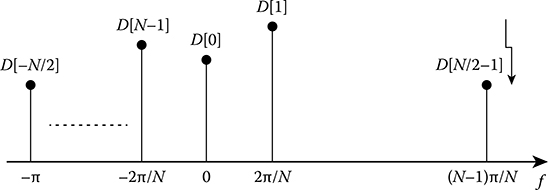
FIGURE 11.2 Frequency-domain representation of an OFDM symbol.
The entire bandwidth allocated for a wavelength channel may be occupied. The data source is distributed over all subcarriers. Thus, each subcarrier transports a small amount of the information. Thus, by this lowering of the bit rate per subcarrier channel, the ISI due to the distortion of the channel can be significantly reduced.
11.1.1.2 Orthogonality
The complex baseband OFDM signal s(t) can be written as
where k is the time index, N is the total number of subcarriers, T = NTs is the stretched OFDM symbol period as a result of the conversion from serial to parallel width, and Ts is the sampling period. an(k) is the kth data symbol of the nth subcarrier and gn(t) is the baseband data pulse given by

FIGURE 11.3 Block diagram of the sampled discrete time model of OFDM system using N-point FFT and IFFT.
g(t) is the pulse-shaping function, which normally is very close to Gaussian after propagating through the optical MZIM.
The orthogonality of the channels requires
with the asterisk * indicating the complex conjugate. Thus, it requires that the selection of the carrier frequency and the pulse-shaping function in such a way that the orthogonality can be achieved.
11.1.1.3 Subcarriers and Pulse Shaping
For orthogonality, each subcarrier should take an integer number of cycles over a symbol period T, and the number of cycles between adjacent subcarriers differs by exactly unity. That means that the frequencies of the subcarriers are multiple of each other.
The pulse shapes of the signals can take the form of rectangular or sinc function and can be written as
where α is the roll-off factor, similar to the raise cosine function.
For the rectangular pulse, we have
However, this “brick wall” pulse shape would be very difficult to be realized in practice, and the raised-cosine shape would be preferred.
The orthogonality can be achieved by setting Δf = 1/T. For simplicity, we can assume that the signals for all sub-carriers, take the shape function expressed as
where “ang(t)” is the data stream fed into each sub carrier channel from the output of the serial-to-parallel converter as shown in Figure 11.4.
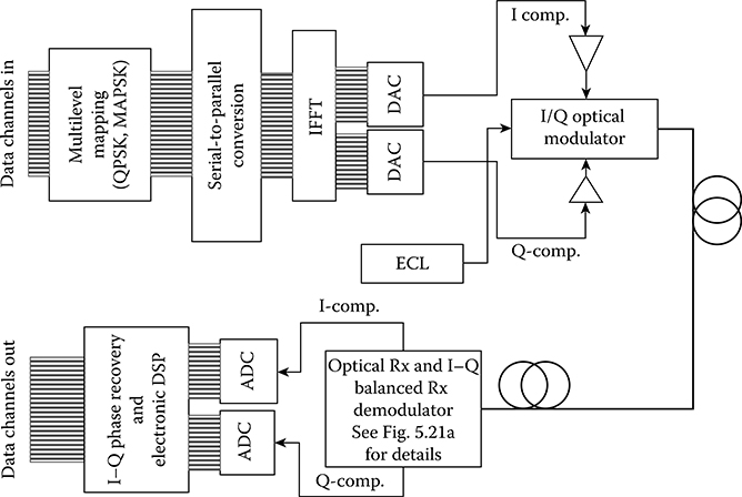
FIGURE 11.4 Schematic diagram of optical OFDM transmitter of a long-haul optical transmission system using OFDM and I–Q multilevel modulation formats. Separate polarized channels PDM are not shown. I = in-phase, Q = quadrature phase, ECL = external cavity lasers, DSP = digital signal processing, IFFT = inverse fast Fourier transform.
Taking the Fourier transform of (6) we have
which is the summation of all sinc functions if the pulse is rectangular shaped. These spectral sinc functions would cross over at the null of each other and their peaks. On the other hand if the temporal function of the data pulses for the sub-carrier channels follow a sin(t)/t profile, then the frequency spectrum of the channel would be rectangular and thus they can be separated with minimum crosstalk. Thus, we can have
with Δf = 1/T.
Therefore, the spectrum of OFDM signal takes the form
which is made up by a number of rectangular spectra separated by Δf.
In practice, the availability of rectangular time pulse shape would not be possible but with certain raised-cosine features, while for sinc shape pulses can be generated without difficulty by using a transmission filter in the electrical domain. The spectrum of OFDM signal is thus the summation of the sinc-shaped spectra of all the subchannels. If the number of subcarrier channels is sufficiently high, then one would obtain a flat rectangular spectrum [2].
The orthogonal subchannels can be generated using IFFT or FFT normally available from digital signal processors.
11.1.1.4 OFDM Receiver
In a conventional FDM system, the subchannels are normally separated by filtering using banks of filters and demodulators. For orthogonal signals, the subchannels can be separated by correlation techniques [3,4].
11.1.2 FFTand IFFT-Based OFDM Principles
To recover or demodulate the subcarrier channels, it is possible to use a bank of filters or alternatively use a local oscillator at the receiver to tune to the sub-channels in order to separate the subchannels. The use of a bank of filters is very costly and processing by DSP under FFT would ease the decoding. Recently, the speed of DSP has increased significantly. Certainly, the FFT and IFFT are the main features of these processors. The main feature of the FFT and IFFT is that the sampling and their sampled transformed subchannels are orthogonal. Thus, they can be effectively used in the transmitter and the receiver of OFDM systems. The OFDM discrete model is shown in Figure 11.4. Thus, the signal is defined in the frequency domain at the transmitter. It is a sampled digital signal and is defined such that the discrete Fourier spectrum exists only at the discrete frequencies. Each OFDM subchannel corresponds to one element of this discrete Fourier spectrum. The magnitude and phase of the carrier depends on the data transmitted. The serial-stream input data sequence is converted into parallel that would then be represented as the components of the frequency spectra, D[n], with equally spaced frequencies fn = 2πn/N for n = 0,1,…,N. Thus, D[0] represents the DC component of the frequency spectrum of OFDM signals. The frequency representation of the signal are shown in Figures 11.1 and 11.2.
An N-point inverse FFT block (the DSP Processor) then generates the time-domain components whose prefix indexes are inserted at the transmitter side and then removed at the receiving side, as shown in Figure 11.3. Thus, the signal at this stage is in analog form, as shown in Figure 11.4, padded with zeros for a cyclic discrete Fourier transform. They are then converted from parallel form into serial form and used for modulating the optical modulator. The passband optical signals are then transmitted over the channel.
The definition of the N-point inverse discrete Fourier transform (IDFT) is
where N is the symbol length. After the pulse shaping of a rectangular function of
The sequence d[n] in the time domain is given by
gn[k] can be considered as the baseband pulse, which is considered to be orthogonal and satisfying the condition.
Thus, a rectangular or sinc pulse shaper can be inserted between the serial-to-parallel and the IFFT blocks, and then multiplied by the subcarrier frequency and then superimposed and multiplied by a factor 1/N.
At the receiver, after the photodetection and electronic preamplification, the noisy time-domain OFDM samples are converted to its corresponding frequency-domain symbols by an N-point FF. The coefficients of an N-point discrete Fourier transforms (DFT) are given by
An N-point DFT is equivalent to a bank of N-orthogonal “matched filters” matched to the corresponding “baseband pulses” in IDFT, followed by samplers that sample once per N symbols. The impulse of the matched filter can be written as
This follows the logical sequence of
After sampling at the instant k = 0, the frequency spectral component C[n] becomes
which is the DFT of y[k].
11.2 Optical OFDM Transmission Systems
Orthogonality is achieved by placing the different RF carriers onto a fixed frequency grid and assuming rectangular pulse shaping. For OFDM, the signal can be described as the output of a discrete inverse Fourier transform block using the parallel complex data symbols as input. This property has been one of the main driving aspects for OFDM in the past, since modulation and demodulation of a high number of carriers can be realized by simple DSP instead of using many local oscillators in the transmitter and receiver. Recently, OFDM has become attractive for digital optical communications [5,6]. Using OFDM appears to be very attractive since the low bandwidth occupied by a single OFDM channel increases the robustness toward fiber dispersion drastically, allowing the transmission of high data rates of 40 Gbps and more over hundreds of kilometers without the need for dispersion compensation [2]. In the same way as for modulation formats such as DPSK or DQPSK that were introduced in recent years, for OFDM too, the challenge for optical system engineers is to adapt a classical technology to the special properties of the optical channel and the requirements of optical transmitters and receivers.
However, Ref. [7] shows that an optical SSB modulation can assist in the combat of fiber dispersion. SSB can be achieved by driving the MZIM with two microwave signals π/2 phase shift with each other or by optical filtering (VSB), as shown in Chapters 2 and 9. However, the truly SSB transmitter using dual-drive and π/2 phase shift is preferred so as to preserve the energy contained within the bands of the signals. In optical SSB, the phase information can be preserved after the square law detection of the photodetector and the chromatic dispersion (CD) is limited by reducing the optical spectral bandwidth by a factor of 2 [5].
Two approaches have been reported recently. An intuitive approach introduced by Llorente et al. [6] makes use of the fact that the wavelength-division multiplexing (WDM) technique itself already realizes data transmission over a certain number of different carriers. By means of special pulse shaping and carrier wavelength selection, the orthogonality between the different wavelength channels can be achieved, resulting in the so-called orthogonal WDM technique (OWDM). However, in this way, the option of simple modulation and demodulation by means of DFTs cannot be utilized as this kind of DSP is not available in the optical domain.
The basic OFDM transmitter and receiver configurations are given in Figure 11.5a [8]. Data streams (e.g., 1 Gbps) are mapped into a two-dimensional signal point from a point signal constellation such as QAM. The complex-valued signal points from all subchannels are considered as the values of the DFT of a multicarrier OFDM signal. The serial-to-parallel converter arranges the sequences into equivalent discrete frequency domains. By selecting the number of subchannels, sufficiently large, the OFDM symbol interval can be made much larger than the dispersed pulse width in a single-carrier system, resulting in an arbitrary small intersymbol interference (ISI). The OFDM symbol, shown in Figure 11.5, is generated under software processing, as follows: input QAM symbols are zero-padded to obtain input samples for inverse fast Fourier transform (IFFT); the samples are inserted to create the guard band; and the OFDM symbol is multiplied by the window function, which can be represented by a raised-cosine function. The purpose of cyclic extension is to preserve the orthogonality among subcarriers even when the neighboring OFDM symbols partially overlap due to dispersion.
The principles of FFT and IFFT for OFDM symbol generations are shown in Figure 11.3. Section 3.4.7 of Chapter 3 has also outlined the principles of a OFDM transmission system. A system arrangement of the OFDM for optical transmission in a laboratory demonstration is shown in Figure 11.5. The data sequences are arranged in the sampled domain, and then to the frequency domain, and then to the time domain representing the OFDM waves, which would look like analog waveforms, as shown in Figure 11.5b and c (see also, Section 3.4.8, Figure 3.37). Each individual channel at the input would carry the same data rate sequence. These sequences can be generated from an arbitrary waveform generator. The multiplexed channels are then combined and converted to time domain using the IFFT module, and then converted to the analog version via the two digital-to-analog converters. These orthogonal data sequences are then used to modulate I and Q optical waveguide sections of the electro-optical modulator to generate the orthogonal channels in the optical domain. Similar decoding of I and Q channels are performed in the electronic domain after the optical transmission and optical–electronic conversion via the photodetector and electronic amplifier. Figure 11.6 illustrates similar transmission systems with the demodulation of the I and Q channels in the electrical domain, while these functions are implemented in the hybrid optical coupler in the optical domain in which the π/2 phase shift for the I and Q can be done by a π/2 shift in the optical domain by using pyro-optic effects via an electrode heating to change the refractive index of the optical path of either I or Q optical signals. This is commonly done in the PLC (planar lightwave circuit) optical hybrid couple.
In comparison with other optical transmitters, the optical OFDM transmitter will require a DSP and DAC for shaping the pulse spectrum and then the IFFT operation so as to generate the OFDM analog signals to modulate the optical modulator.
The performance of an OFDM coherent and transmission under back-to-back and over 1000 km of SSMF spans without DCM (dispersion compensation modules) as shown in Figure 11.7a and b, respectively, indicates the resilience of OFDM format to dispersion with an OSNR of 8 dB for a BER of 1e−3, which is the error-free rate under FEC integration. Note that polarization multiplexing is employed in the systems where both polarized channels are detected and extracted for BER as a function of the OSNR (measured over 0.1 nm spectral width).
In OFDM, the serial data sequence, with a symbol period of Ts and a symbol rate of 1/Ts, is split up into N-parallel substreams (subchannels).
An alternative method [9] is the generation of an electrical OFDM signal by means of electrical signal processing followed by modulation onto a single optical carrier [10,11]. This approach is known as optical OFDM (oOFDM). Here, the modulation is a two-step process: first, the electrical OFDM signal is already a broadband bandpass signal, which is then modulated onto the optical carrier. Second, to increase data throughput, oOFDM can be combined with WDM, resulting in a multi-Tbps transmission system as shown in Figure 11.4. Nevertheless, oOFDM itself offers different options for implementation. An important issue is optical demodulation that can be realized either by means of direct detection (DD) or coherent detection CoDet, including a local laser oscillator. DD is preferable due to its simplicity. However, for DD, the optical intensity has to be modulated. Due to the fact that the electrical OFDM signal is quasi-analog with zero mean and high peak-to-average ratio, the majority of the optical power has to be wasted for the optical carrier. That means there is an additional DC value of the complex baseband signal, resulting in low receiver sensitivity. For chromatic dispersion (CD), in addition, the bandwidth efficiency is twice as high as for DD, since for pure intensity modulation, a double-sideband signal is inherently generated. For CoDet, a complex optical I–Q modulator, composed of two real modulators in parallel followed by superposition with π/2 phase shift, allows for transmission of twice as much data within the same bandwidth. For intensity modulation, the bandwidth efficiency may be increased by suppressing one of the redundant sidebands, resulting in oOFDM with single-sideband (SSB) transmission. First, the serial data sequence in can be converted to parallel streams. These parallel data sequences are then mapped to QAM constellations in the frequency domain, and then by IFFT converted back to the time domain. The time-domain signals are in I and Q components, which are then fed into an I–Q optical modulator. This optical modulation can be DQPSK or any other multilevel modulation subsystem. At the end of the optical fiber transmission, I and Q components are detected either by DD or CD. For coherent detection, a 2 × 4 π/2 hybrid coupler is used to mix the polarized optical fields of the local oscillator and that of the received signals. The outputs of the couplers are then fed into balanced optical receivers. The mixing of the local laser source and that of the signals preserves the phase of the signals, which are then processed by a high-speed electronic digital processor. For DD, I and Q components are detected differentially, and the amplitude and phase detection are then compared and processed similarly as for the coherent case.

FIGURE 11.5 An optical FFT-IFFT-based (a) OFDM system including representative waveforms and spectra, (b) typical time-domain OFDM signals, and (c) power spectral density normalized in the frequency domain of OFDM signal with 512 subcarriers for 40 Gbps signals and QPSK modulation. (Note: electrical mixers for I and Q components recovery in electrical domain.)

FIGURE 11.6 Schematic of an optical FFT-/IFFT-based OFDM system. S/P and P/S = serial-to-parallel conversion and vice versa. PD = photodetector, TIA = transimpedance amplifier (see also Figure 3.37 of Chapter 3 for more details). (Note electrical demodulation of in-phase and quadrature components.)
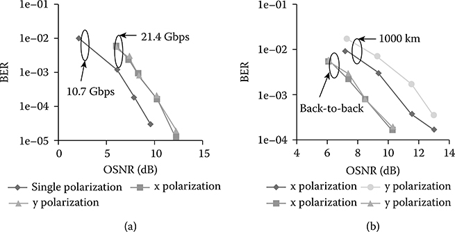
FIGURE 11.7 BER versus OSNR under coherent reception (a) back-to-back and (b) 1000 km non-DCM optically amplified spans. (Extracted with permission from W. Shieh and C. Athaudage, Coherent Optical Orthogonal Frequency Division Multiplexing, 2006.)
In order to show the robustness of oOFDM toward fiber dispersion and also fiber nonlinearity, numerical simulations are carried out for a data stream of 42.7 Gbps data rate. The number of OFDM channels can be varied between Nmin = 256 and Nmax = 2048. A guard interval of 12 ns can be inserted, a strategy belonging inherently to OFDM technology that ensures orthogonality of the different channels in case of a transmission channel with memory. For the optical modulation, intensity modulation using a single Mach–Zehnder modulator in conjunction with SSB filtering and direct detection was implemented. The nonlinear optical transmission channel consisted of eight 80 km non-DCF spans of SSMF. MZIM with linearization should be used [12]. As a criterion for performance, the required OSNR for a BER of 10−3 (Monte Carlo) is measured. Using FEC subsystem in cascade with the optical receiver, after decoding and error correction the BER is equivalent to an error rate below 10–9. This also depends on the specific code and the extra number of bits of the FEC.
Figure 11.8 [8] shows the required OSNR as a function of fiber launch power for different values of N. The transmission is error free (1e−9) over 640 km of SSMF or a dispersion factor of about 1100 ps/nm without dispersion compensation. It can be explained by the fact that, even for the lowest value of Nmin = 256, each subchannel occupies a bandwidth of approximately 42.7 GHz/256 = 177 MHz, resulting in high robustness toward fiber dispersion.

FIGURE 11.8 Simulation result for 42.7 Gbps oOFDM transmission over 640 km of SSMF; OSNR required for BER = 10−3 as function of fiber launch power. (Extracted with permission from A. Ali, Investigations of OFDM Transmission for Direct Detection Optical Systems, Dr. Ing. Dissertation, Albrechts Christian Universitaet zu Kiel, 2012.)
The principal difficulties of OFDM are that the pure delay is due to the variation of the refractive index of the fiber with respect to the optical frequency, leading to bunching of the subchannels and hence increase in the optical power; thus, unexpected SPM may occur in a random manner.
11.2.1 Impacts of Nonlinear Modulation Effects on Optical OFDM
The MZIM is biased at a quadrature point where the power transfer characteristic is linearizable. By means of low modulation depth, the nonlinear distortions due to the MZM can be considered to be arbitrarily small, hence leading to a low ratio of useful power to carrier power, and thus low sensitivity. Therefore, the modulation depth is a compromise between these constraints.
Figure 11.9 shows [8,13,14] results for the BER versus OSNR under back-to-back transmission, where the BER is obtained by Monte Carlo simulation. The OSNR for BER = 10−3 is plotted versus normalized driving voltage, as shown in Figure 11.9. The normalization is performed such that minimum and maximum optical output power can be obtained for instantaneous input voltages of −0.5 and 0.5, respectively. Beyond these values, clipping occurs, and intermodulation distortion also exists, due to MZM characteristics. The OFDM signal is analog, having nearly Gaussian amplitude distribution [4]. In good approximation, the peak voltage is within an interval from plus to minus the triple of the RMS voltage. This relation is used to create the lower from the upper of the two horizontal axes. The clipping threshold obtained for a peak voltage of ±0.5 is also given. Finally, the impact of MZM nonlinearity, which, within the range of acceptable sensitivity, obviously does not depend significantly on N, is identified by means of the dashed line.

FIGURE 11.9 Required OSNR for BER = 10−3 as a function of driving voltage swings fed to MZIM electrodes. (Extracted with permission from A. Ali, Investigations of OFDM Transmission for Direct Detection Optical Systems, Dr. Ing. Dissertation, Albrechts Christian Universitaet zu Kiel, 2012.)
Figure 11.9 depicts the nonlinear resilience of the fiber transmission link including 8 × 80 km SSMF without dispersion compensation. In order to investigate the impact of linear factor one by one, the MZM is driven in the quasi-linear range with a normalized effective voltage swing of ≈0.15, resulting in a back-to-back OSNR of ≈25.5 dB. This value is significantly above those reported, for example, in Ref. [15], which is due to incoherent detection and higher bandwidth. For low values of launch power, Figure 11.9 shows the robustness of oOFDM toward fiber dispersion, as the OSNR penalty achieved with ≈11,000 ps/nm accumulated dispersion is negligible. In the nonlinear regime, however, penalty increases rapidly. Beyond 8 dBm launch power at the fiber input, the BER does not fall below 10−3, due to strong signal distortion. The optical power consists of a strong DC component and a weaker AC component carrying the OFDM signal. Since only the AC component results in signal distortion, the acceptable launch power found in this contribution is higher than for coherent detection.

FIGURE 11.10 Eye opening penalty of OFDM as compared with NRZ-ASK with different guard interval times of 25, 50, and 100 ps for 42.7 Gbps bit rate.
Figure 11.10 shows the eye opening penalty of modulation formats NRZ-ASK and OFDM with guard intervals of 25, 50, and 100 ps. It shows clearly the superiority of OFDM over ASK at 42.7 Gbps bit rate.*
Except for the value for N = 512 at a launched power of 8 dBm, attributed to limited simulation accuracy, the result does not depend on N. Increasing N decreases the separation between the subchannels, and fiber nonlinearity is expected to cause strong XPM and FWM. However, with increasing N, the power per subchannel is decreased. Apparently, these two aspects cancelled out each other so that equal performance for all N is achieved.
The impact of nonlinear modulator characteristic and Kerr effect shows that, for an uncompensated oOFDM 8 × 80 km fiber link with a varying number N of subcarriers, both impairments are independent of N. Obviously, oOFDM is quite robust toward the specific nonlinear impairments in fiber-optic transmission systems.
11.2.2 Dispersion Tolerance
The variation of the eye opening penalty as a function of the ratio of the guard interval and the bit period with the fiber SSMF length as a parameter is obtained as shown in Figure 11.11. This indicates that the guard interval is very critical for different lengths of the fibers, and thus also the bit rate and the number of subcarriers.
11.2.3 Resilience to PMD Effects
Reference [14] reports the first experiment of PMD impact on fiber nonlinearity in coherent optical OFDM (CO-OFDM) systems. The optimal Q value at 10.7 Gbps has been improved by 1 dB after the introduction of DGD of 900 ps with the variation of the Q value against the launched power, as shown in Figure 11.12 [16]. 900 ps is equivalent to 22 symbol periods of the baud rate of 25 GB. This is a very substantial resilience rate. Note that, if both polarized channels are employed as such in the Polarization Division Multiplexing 9pDm0 systems, the two polarized channels which are received and demultiplexed, then they can be processed by 2 × 2 MIMO (multiple input multiple output) processing technique to improve the BER and minimize the required OSNR, as shown in Figure 11.7.
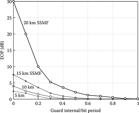
FIGURE 11.11 Eye opening penalty of OFDM against the ratio of the guard interval and bit period with fiber length as a parameter, N = 8.

FIGURE 11.12 System Q as a function of launch power for PMD-supported and non-PMD-supported OFDM-QPSK transmission systems. Note the rotation of the signal constellation. (Extracted with permission from Y. Ma et al., Electron. Lett., Vol. 43, pp. 943–945, 2007.)
11.3 OFDM and DQPSK Formats for 100 Gbps Ethernet
For 100 Gbps Ethernet, the decomposition of the bit rate to symbol rates under multilevel modulation formats can be referred to Chapter 7. The OFDM offers significantly lower symbol rate due to the decomposition into several subchannels. Reference [8] reported the transmission performance of RZ-DQPSK formats over 75 km of SSMF, as well as RZ-ASK with OSNR of 22 dB and 36 dB, respectively.
On the contrary, the OFDM can combine a large number of parallel data streams into one broadband data stream with high spectral efficiency, and would offer significant reduction of bit rates into symbol rates. This would challenge the use of multilevel modulation formats. However, there are still several issues to be examined by optical OFDM, such as high peak-to-average carrier ratio or FWM effects and other nonlinear effects.
OFDM schemes offer the following advantages to optical long-haul, metro, and access networks:
Different users can be assigned with different OFDM subcarriers within one OFDM band of N-subcarriers, as shown in Figure 11.13a. This assignment is very much suitable for the case of a massive MIMO antenna in which each antenna element would be assigned with a specific channel. These MIMO antennae would carry wireless OFDM signals, and this oOFDM transport technique would be most suitable for the convergence between wireless and optical transport layers. Furthermore, each channel can be assigned different slots for the case of TDM (see Figure 11.13b), as well as different wavelengths (see Figure 11.13c).
Regarding speed and distance: 100 Gbps/λ downstream and same for upstream. 100 km for access, 1000 km for metro, and 5000−10,000 km for long haul.
On flexibility: OFDM offers adaptive modulation and FEC on subcarrier basis, dynamic bandwidth allocation in time and frequency, transparency to arbitrary services, and optically transparent ONUs.

FIGURE 11.13 OFDM in different assignments of channels and subcarriers and wavelength: (a) different subcarriers to different channels, (b) different slots to TDM channels, and (c) different wavelength for OFDM symbols.
On cost efficiency: OFDM offers colorless architecture; stable, accurate DSP-based operation; and nondisruptiveness to legacy optical data networks (ODNs).
On access passive optical networks (PON): Orthogonal frequency division multiplexing (OFDM) PON: very well-suited for future PON systems, transparent to emerging heterogeneous applications, highly flexible, dynamic bandwidth allocation, and nondisruptive to legacy ODN.
Recent demonstrations of ultra-high-speed OFDMA PON by NEC and Huawei OFDM with aggregate speed of 108 Gbps/downstream and upstream, feasible on class C+ ODN (30+ dB power budget), highly dispersion tolerant (60–100 km transmission).
However, OFDM requires advanced DSP, which has been under intense research and development. DSP complexity: IFFT/FFT dominates, ~log(N) scaling, and optimized algorithms.
11.4 Concluding Remarks
OFDM is strongly suitable as a modulation technique for optical digital communications, especially for lowering the ultra-high-speed 100 Gbps Ethernet to a much more acceptable rate per subchannel. As multicarrier channels with natural orthogonality from the FFT and IFFT, it is much more efficient than the use of a single carrier as seen in other advanced modulation formats described in most chapters of this book. By closely spacing all the subchannels via the orthogonality, one can increase the spectral efficiency.
The pulse-shaping function can certainly influence the orthogonality of the subchannels and minimize the crosstalks between channels. The sinc function in the time domain would be the best choice. The guard bands influence the transmission performance of OFDM transmissions.
OFDM is shown to be more resilient to nonlinearity and PDM, as well as CD. Coherent OFDM offers higher receiver sensitivity or lower eye opening penalty than the direct detection OFDM without much more complexity, as the processing of the received optical sequence can be implemented in the electronic domain.
The trends for oOFDM in optical networking are as follows:
DSP-based system cost can be significantly and rapidly reduced by component integration and mass production.
Optimized OFDM algorithms reused from wireless and wireline building blocks.
Next-generation 100 Gbps long-haul fiber transmission will be heavily DSP-based, and 50+ GSa/s, two-channel ADC chips and 10–30 GS/s, two-channel DAC chips must be commercially available.
Intensive ongoing effort in parallelized, real-time DSP architectures.
Aggressive 100 Gbps DSP development for fiber transmission expected to have favorable effect on ultra-high-speed OFDM-PON for access and metro networks.
The key challenges to be tackled rest in
DSP two-channel ADC/DAC, DSP processor key components.
Favorable technology trends in terms of cost profile.
41.25 Gbps real-time, variable-rate receiver for WDM-OFDM and higher bit rates to 100 Gbps must be developed.
RefeRences
1. R. V. Nee and R. Prasad, OFDM for Wireless Communications, Norwood: Artech House, 2000.
2. J. Proakis, Digital Communications, New York: McGraw-Hill, 2002.
3. L. Hanzo, S. X. Ng, T. Keller, and W. Webb, Quadrature Amplitude Modulation: From Basics to Adaptive Trellis Coded, Turbo-Equalized Space-Time Coded OFDM, CDMA and MC-CDMA Systems, 2nd ed., Chichester, England: IEEE Press, 2004.
4. L. Hanzo, M. Münster, B. J. Choi, and T. Keller, OFDM and MC-CDMA for Broadband Multi-User Communications, WLANs and Broadcasting, NY: Wiley, 2003.
5. M. Sieben, J. Conradi, and D. E. Dodds, Optical single-sideband transmission at 10 Gbps using electrical dispersion compensation, IEEE J. Lightwave Technol., Vol. 17, No. 10, pp. 2059–2068, 1999.
6. R. Llorente, J. H. Lee, R. Clavero, M. Ibsen, and J. Martí, Orthogonal wavelength-division-multiplexing technique feasibility evaluation, J. Lightwave Technol., Vol. 23, pp. 1145–1151, 2005.
7. A. J. Lowery and J. Armstrong, Orthogonal-frequency-division multiplexing for dispersion compensation in long haul WDM systems, Opt. Express, Vol. 14, No. 6, pp. 2079–2084, 2006.
8. A. Ali, Investigations of OFDM Transmission for Direct Detection Optical Systems, Dr. Ing. Dissertation, Albrechts Christian Universitaet zu Kiel, 2012.
9. J. Leibrich, A. Ali, and W. Rosenkranz, Optical OFDM as a promising technique for bandwidth-efficient high-speed data transmission over optical fiber, in Proceedings of the 12th International OFDM-Workshop 2007 (InOWo 2007), 29–30 August 2007, Hamburg, Germany, 2007.
10. A. J. Lowery, L. Du, and J. Armstrong, Orthogonal frequency division multiplexing for adaptive dispersion compensation in long haul WDM systems, in Proceedings of the OFC 2006, Anaheim, CA, USA, paper PDP39, 2006.
11. W. Shieh and C. Athaudage, Coherent optical orthogonal frequency division multiplexing, Electron. Lett., Vol. 42. pp. 587–589, 2006.
12. X. J. Meng, A. Yacoubian, and J. H. Bechtel, Electro-optical pre-distortion technique for linearization of Mach-Zehnder modulators, Electron. Lett., Vol. 37, No. 25, pp. 1545–1547, 2001.
13. A. Ali, J. Leibrich, and W. Rosenkranz, Impact of nonlinearities on optical OFDM with direct detection, in Proceedings of the ECOC 2007, Berlin, Germany, 2007.
14. A. Ali, Orthogonal Frequency Division Multiplexing in Optical Transmission Systems with High Spectral Efficiency, Master Thesis Dissertation, Technische Facultaet, University of Kiel, Kiel, Germany, 2007.
15. S. L. Jansen, I. Morita, N. Takeda, and H. Tanaka, 20-Gb/s OFDM Transmission over 4,160-km SSMF Enabled by RF-Pilot Tone Phase Noise Compensation, Proc. Opt. Fiber Conf., OFC, Anaheim, CL, 2007.
16. Y. Ma, W. Shieh, and X. Yi, Characterization of nonlinearity performance for coherent optical OFDM signals under the influence of PMD, Electron. Lett., Vol. 43, pp. 943–945, 2007.
*Simulation developed under MOVE_IT (MATLAB®), and simulation platform provided by M. Ali of Technische Facultaet, Universit of Kiel.