
8
Continuous Phase Modulation Format Optical Systems
This chapter describes the modulation scheme that uses the modulation of the phase lightwave carrier, in which the change of the phase during a one-bit state would be continuous, that is, two frequencies, and hence the term continuous phase frequency shift keying (CPFSK). When the two-frequency signal components are orthogonal, the CPFSK is considered as minimum shift keying (MSK). This scheme is also presented. The generation of modulated signals and propagation and detection schemes are then presented, after which the transmission performance is described.
8.1 Introduction
The generation of MSK requires a linear variation of the phase, and hence a constant frequency of the optical carrier. However, the generation of the optical phase may be preferred by driving an optical modulator using a sinusoidal signal for practical implementation. Thus, a nonlinear variation of the carrier phase results, and hence some distortion effects are produced. In this chapter, we investigate the use of linear and nonlinear phase-shaping filtering and their impact on MSK-modulated optical signals transmission over optically amplified long-haul communications systems. The evolution of the phasor of the in-phase and quadrature components is illustrated for lightwave-modulated signal transmission. The distinct features of three different MSK modulation formats—linear MSK, weakly nonlinear MSK, and strongly nonlinear MSK—and their transmissions are simulated. The transmission performance obtained indicates the resilience of the MSK signals in transmission over optically amplified multispans.
Recent years have witnessed intensive interest in the employment of advanced modulation formats to explore their advantages and performance in high-density and long-haul transmission systems. Return-to-zero (RZ) and non-return-to-zero (NRZ) without or with carrier suppression (CSRZ) formats are associated with shift keying (SK) modulation schemes such as amplitude (ASK), phase (PSK), and differential phase (DPSK, DQPSK) [1,2]. Differential detection offers the best technological implementation owing to the nonrequirement of coherent sources and avoidance of polarization control of the mixing of the signals and a local oscillator in the multi-THz frequency range. Continuous phase modulation (CPM) is also another form of phase shift keying (PSK) in which the phase of the optical carrier evolves continuously from one phase state to the other. For MSK, the phase change is limited to π/2. Although MSK is a well-known modulation format in radio frequency digital communications, it has only been attracting interest in optical system research in the past few years [3, 4 and 5]. The phase continuous evolution of MSK has many interesting features: the main lobe of the power spectrum is wider than that of quadrature phase shift keying (QPSK) and differential phase shift keying (DPSK) and the side lobes of the MSK signal spectrum are much lower, allowing ease of optical filtering and hence less distortion due to dispersion effects. In addition, higher signal energy is concentrated in the main lobe of MSK spectrum than its side lobes, leading to a better signal-to-noise ratio at the receiver.
Advanced modulation formats for 40 Gbps and higher-bit-rate long-haul optical transmission systems have recently attracted intensive research, including various amplitude and discrete differential phase modulation and pulse shape formats (ASK-NRZ/RZ/CSRZ, DPSK, and DQPSK-NRZ/RZ/CSRZ). However, there are only a few reports on optical CPM schemes using external electro-optical modulators [1, 2, 3 and 4]. Compared to discrete phase modulation, CPM signals have very interesting and attractive characteristics including high spectral efficiency, higher energy concentration in the signal bands, and more robustness to interchannel crosstalk in dense wavelength division multiplexed (DWDM) owing to greater suppression of the side lobes, which has recently arisen as a critical issue in DWDM optical systems [5,6].
In bandwidth-limited digital communications, including wireless and satellite digital transmission, MSK has proved to be a very efficient modulation format owing to its prominent spectral efficiency, high sideband suppression, constant envelope, and high energy concentration in the main spectral lobe. In modern high-capacity and high-performance optical systems, we have witnessed an acceleration of the transmission bit rate approaching 40 Gbps and even up to 160 Gbps. At these ultra-high bit transmission speeds, the essence of efficient modulation formats for long-haul transmission is critical. There are several technical published works on advanced modulation techniques for optical transmission, which mostly focus on discrete phase modulation including binary DPSK and DQPSK [1, 2 and 3] with various pulse carving formats including NRZ and CSRZ [2,4]. However, there is only a limited number of studies on the MSK modulation format [5, 6, 7 and 8]. The features of MSK compared to other modulation formats have prompted researchers to investigate its suitability for high-capacity long-haul transmission. The side lobes of the MSK power spectrum are greatly suppressed, giving it good dispersion tolerance and avoiding interchannel crosstalk. Thus, this modulation is of interest for further investigation.
Two different proposals for transmitter configurations for the generation of linear and nonlinear phase optical MSK modulation are reported in Ref. [9]. Brief operational descriptions of these two transmitter configurations are presented in Section 8.2, whereas the direct detection techniques for both linear and nonlinear optical MSK signals are covered in Section 8.3. Our simulation models for the modulation and system transmission are based on the MATLAB® and Simulink® platform [10] with detailed discussions in Section 8.4. In this chapter, we have also proved that the optical MSK signal is capable of propagating over an optically amplified and fully dispersion-compensated system. The performance of the conventional MSK format and also that of the weakly and strongly nonlinear optical MSK sequences are evaluated.
The MSK format exhibits dual alternating frequencies and offers the orthogonality in phase of the envelopes of two consecutive bit periods. More interestingly, MSK can be considered as either a special case of CPFSK or an staggered/offset QPSK in which I and Q components are interleaved with each other [7]. These characteristics are greatly advantageous for optically amplified long-haul transmission because such a compact spectrum potentially gives a good dispersion tolerance, making MSK a suitable candidate for DWDM systems.
This chapter thus investigates a number of novel structures of photonic transmitters for the generation of optical MSK signals. The theoretical background of MSK modulation formats discussing employing two different approaches is presented in Section 8.2. Section 8.3 proposes two configurations of optical MSK transmitters that employ (1) two cascaded electro-optic phase modulators (E-OPMs) and (2) parallel dual-drive Mach–Zehnder modulators (MZMs). Different types of linear and nonlinear phase-shaped optical MSK sequences can be generated. The precoder for the I–Q optical MSK structure is also derived in this section. We present in Section 8.4 a simple noncoherent configuration for detection of MSK and nonlinear MSK-modulated sequences. The optical detection of MSK and nonlinear MSK signals employs a π/2 phase shift in one arm of the Mach–Zehnder interferometric delay (MZIM) balanced receiver. New techniques in the measurement of the BERs with the probability density function (pdf) as described in Chapter 4 of the received signals after decision sampling can be computed with superposition of a number of weighted Gaussian pdfs. The following performance results and observations are obtained in Section 8.5: (1) spectral characteristics of linear and nonlinear MSK-modulated signals and (2) improvement in dispersion tolerance of MSK and nonlinear MSK over ASK and DPSK counterparts.
Recently, advanced modulation formats have attracted intensive research for long-haul optical transmission systems including various amplitude and discrete differential phase modulation and pulse shape formats (ASK-NRZ/RZ/CSRZ, DPSK, and DQPSK-NRZ/RZ/CSRZ). For the case of phase modulation, the phases of the optical carrier are discretely coded with “0”, “π” (DPSK) or “0”, “π” and “π/2, −π/2” (DQPSK). Although, the differential phase modulation techniques offer better spectral properties, a higher energy concentration in the signal bands, and more robustness to combat the nonlinearity impairments as compared to the amplitude modulation formats, phase continuity would offer even better spectral efficiency and at least 20 dB better suppression of the side lobes. MSK exhibits a dual alternating frequency between the two consecutive bit periods and is considered to offer the best scheme as this offers the orthogonal property of the two-frequency modulation of the carrier lightwaves embedded within the consecutive bits. Furthermore, it offers maximum simplicity in the implementation of the modulation in the photonic domain.
This chapter thus investigates a number of novel structures of photonic transmitters and differential noncoherent balanced receivers for the generation and detection of MSK optical signals as follows.
Cascaded electro-optic phase modulators MSK transmitter: This structure employs two cascaded optical phase modulators (OPMs). The first OPM plays the role of modulating the binary data logic into two carrier frequencies deviating from the optical carrier of the laser source by a quarter of the bit rate. The second OPM enforces the phase continuity of the lightwave carrier at every bit transition. The driving voltage of this second OPM is precoded in such as a way that the phase discrepancy due to frequency modulation of the first OPM will be compensated, hence preserving the phase continuity characteristic of the MSK signal. Utilizing this double phase modulation configuration, different types of linear and nonlinear CPM phase-shaping signals, including MSK, weakly MSK, and linear-sinusoidal MSK, can be generated. The optical spectra of the modulation scheme obtained confirm the bandwidth efficiency of this novel optical MSK transmitter.
Parallel dual-drive MZM optical MSK transmitter: In this second configuration, MSK signals with small ripple of approximately 5% signal amplitude level can be generated. The optical spectrum is demonstrated to be equivalent to the configuration depicted in Figure 8.1. This configuration can be implemented using commercially available dual-drive intensity interferometric electro-optic modulators.
We also present a simple noncoherent configuration for detection of the MSK and nonlinear MSK-modulated sequences. The optical detection of MSK and nonlinear MSK signals employs a π/2 OPM followed by the MZIM balanced receiver.
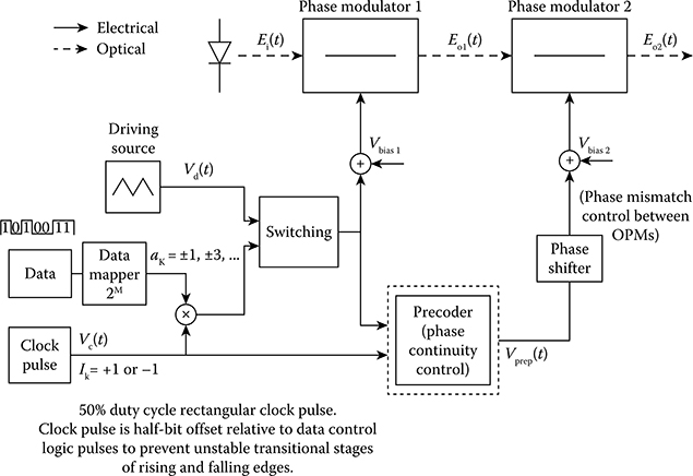
FIGURE 8.1 Block diagram of optical MSK transmitter employing two cascaded optical phase modulators.
The following performance results and observations are obtained:
The modeling platform based on MATLAB and Simulink is developed for the transmission systems.
Spectral characteristics of linear and nonlinear MSK-modulated signals are obtained.
Improvement of the dispersion tolerance of MSK and nonlinear MSK over ASK and DPSK is achieved.
Novel techniques in the measurement of BERs with the pdf of received signals after decision sampling to be computed with the superposition of a number of weighted Gaussian pdfs. This technique has been proved to be effective, convenient, and accurate for estimating the non-Gaussian pdf for the case of CPM and its transmission over long-haul optically amplified systems. The MSK format has been demonstrated via modeling to be a promising candidate in the selection of advanced modulation formats for DWDM long-haul optical transmission system.
8.2 Generation of Optical MSK-Modulated Signals
The two optical MSK transmitter configurations can be referred to in more detail in Ref. [6]. The descriptions of these configurations are briefly addressed in Section 7.2.
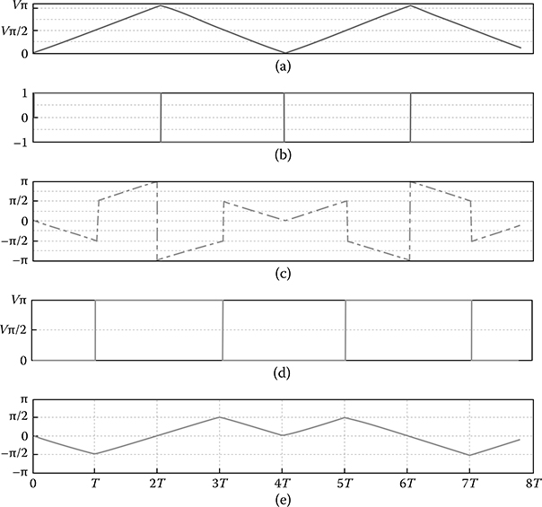
FIGURE 8.2 Evolution of time-domain phase trellis of optical MSK signal sequence [−1 1 1 −1 1 −1 1 1] as inputs and outputs at different stages of the optical MSK transmitter. The notation is denoted in Figure 8.1 accordingly. (a) Vd(t): periodic triangular driving signal for optical MSK signals with a duty cycle of a four-bit period; (b) Vc(t): the clock pulse with a duty cycle of 4T; (c) E01(t): phase output of OPM1; (d) Vprep(t): pre-computed phase compensation driving voltage of OPM2; and (e) E02(t): phase trellis of a transmitted optical MSK sequences at an output of OPM2.
The optical MSK transmitter can be formed by using two cascaded E-OPMs as shown in Figure 8.1. The evolution of the time-domain phase trellis of the optical MSK signal sequence [−1 1 1 −1 1 −1 1 1] as inputs and outputs at different stages of the optical MSK transmitter is tabulated in Figure 8.2. The demonstration of phase compensation for enforcement of phase continuity at bit transitions is given in Figure 8.3. E-OPMs and interferometers operating at a high frequency using resonant-type electrodes have been studied and proposed in Refs. [7,8]. In addition, high-speed electronic driving circuits evolved with the ASIC technology using 0.1 μm GaAs P-HEMT or InP HEMTs [9] enables the realization of the proposed optical MSK transmitter structure. The baseband equivalent optical MSK signal is represented in Figure 8.2.
The first E-OPM enables the frequency modulation of data logic into upper sidebands (USBs) and lower sidebands (LSBs) of the optical carrier with a frequency deviation of fd. Differential phase precoding is not necessary in this configuration owing to the nature of the continuity of the differential phase trellis. By alternating the driving sources Vd(t) to sinusoidal waveforms for simple implementation or a combination of sinusoidal and periodic ramp signals that was first proposed by Amoroso in 1976 [10], different schemes of linear and nonlinear phase-shaping MSK-transmitted sequences can be generated.

FIGURE 8.3 Demonstration of phase compensation for enforcement of phase continuity at bit transitions: (a) shows the periodic triangular driving signal whose peak voltage is Vπ/8 and a duty cycle of four-bit period, (b) shows the clock pulse corresponding to the driving signal, (c) shows frequency switching with h = ±1/8, ±7/8, (d) shows the computed phase compensation, and (e) shows the phase trellis of an optical quaternary CPFSK.
The second E-OPM enforces the phase continuity of the lightwave carrier at every bit transition. The delay control between the E-OPMs is usually implemented by the phase shifter shown in Figure 8.1. The driving voltage of the second E-OPM is precoded to fully compensate for the transitional phase jump at the output E01(t) of the first E-OPM. The phase continuity characteristic of the optical MSK signals is determined by the algorithm as
where ak = ±1 are the logic levels; Ik = ±1 is a clock pulse whose duty cycle is equal to the period of the driving signal Vd(t), fd is the frequency deviation from the optical carrier frequency, and h = 2fdT is previously defined as the frequency modulation index. In the case of optical MSK, h = 1/2 or fd = 1/(4T). The phase evolution of the continuous phase optical MSK signals are shown with detailed discussion in Figure 8.2. In order to mitigate the effects of the unstable stages of rising and falling edges of the electronic circuits, the clock pulse Vc(t) is offset with the driving voltages Vd(t).
The generated optical signal envelope can be written as
8.3 Detection of M-ary CPFSK-Modulated Optical Signal
The detection of linear and nonlinear optical M-ary CPFSK utilizes the well-known MZDI-balanced receiver. The addition of a π/2 phase on one arm of the MZDI is also introduced. The time delay being a fraction of a bit period enables the phase trellis detection of optical M-ary CPFSK. The detected phase trellis using the proposed technique is shown in Figure 8.3. Figure 8.4 shows the eye phase trellis detection of an optical M-ary CPFSK-modulated signal.

FIGURE 8.4 Eye phase trellis detection of optical M-ary CPFSK-modulated signal.
An optimized ratio of switching frequencies results in the maximum eye open. The detection of optical M-ary CPFSK with delay of Tb/2 at t = (k + 1)Tb/2 is expressed in Equation 8.3
On the same slope of phase in the phase trellis, the differential phase, and hence the modulated frequency levels, can be mapped to detected amplitude levels via Equation 8.4.
8.3.1 Optical MSK Transmitter Using Parallel I–Q MZIMs
The conceptual block diagram of the optical MSK transmitter is shown in Figure 3.30, Chapter 3. The transmitter consists of two dual-drive electro-optic MZM modulators generating chirpless I and Q components of MSK-modulated signals, which is considered as a special case of staggered or offset QPSK. The binary logic data are precoded and de-interleaved into even and odd bit streams, which are interleaved with each other by one-bit duration offset. Figure 3.30, Chapter 3 shows the block diagram configuration of band-limited phase-shaped optical MSK. Two arms of the dual-drive MZM modulator are biased at Vπ/2 and –Vπ/2 and driven with data and data complement. Phase-shaping driving sources can be a periodic triangular voltage source in the case of linear MSK generation or simply a sinusoidal source for generating a nonlinear MSK-like signal, which also obtains the linear phase trellis property but with small ripples introduced in the magnitude.
The magnitude fluctuation level depends on the magnitude of the phase-shaping driving source. High spectral efficiency can be achieved with tight filtering of the driving signals before modulating the electro-optic MZMs. Three types of pulse-shaping filters are investigated including Gaussian, raised-cosine, and squared-root raised-cosine filters. The optical carrier phase trellis of linear and nonlinear optical MSK signals are shown in Figure 8.5.
The generation of linear and nonlinear optical MSK sequences are now briefly discussed.
8.3.1.1 Linear MSK
The pulse-shaping waveform for linear MSK is a triangular waveform with a duty cycle of 4 Tb. The triangular waveform for the quadrature path is delayed by one-bit period with respect to the in-phase path, and hence they are interleaved with each other. The optical MSK signal is the superposition of both even and odd waveforms from the MZIMs. The amplitude of the signal is a constant, clearly displaying the constant amplitude characteristic of CPM. The phase trellis is linear, and the phase transition is continuous as shown in Figure 8.5a. The signal constellation is a perfect circle.

FIGURE 8.5 Phase trellis of (a) linear and (b) nonlinear MSK-transmitted signals.
8.3.1.2 Weakly Nonlinear MSK
The pulse-shaping waveform for weakly nonlinear MSK is a sinusoidal waveform with an amplitude of 1/4Vπ, and its symbol period is equal to a two-bit period (symbol rate of 20 Gbits/s). The in-phase pulse shaper is a cosine waveform, whereas the quadrature pulse shaper is a sine waveform. There is a ripple of approximately 5%. Owing to the sinusoidal pulse shaper, the variation of the phase with time, which is represented by the phase trellis, is nonlinear. Therefore, the rate of frequency change is not constant. This causes a mismatch of the MZIM when the modulated waveforms are added up, resulting in the ripple, as shown in Figure 8.5b.
8.3.1.3 Strongly Nonlinear MSK
The pulse-shaping waveform for strongly nonlinear MSK is a sinusoidal waveform, the same as for the weakly nonlinear case. However, the amplitude of the pulse shaper is Vπ/2. The waveforms are interleaved with each other. The optical MSK signal has a ripple of approximately 26%. This ripple is also caused by the mismatch of the MZIM as the modulating waveform is strongly nonlinear. The effect of nonlinearity is obvious in the phase trellis in Figure 8.4b.
The signal state constellations and eye diagrams of the optical MSK sequences are shown in Figure 8.6a through c for both linear and nonlinear schemes. Note that the magnitude ripples. In the case of the nonlinear configuration, MSK signals with a small ripple of approximately 5% signal amplitude level can be generated. This configuration can be implemented using commercially available dual-drive intensity interferometric electro-optic modulators.

FIGURE 8.6 Constellation diagrams and eye diagrams of optical MSK-transmitted signals: (a) a1–a2, linear; (b) b1–b2, weakly nonlinear; and (c) c1–c2, strongly nonlinear transmission.
The conceptual block diagram of the optical MSK transmitter is shown in Figures 8.1. The transmitter consists of two dual-drive electro-optical MZM modulators generating chirpless I and Q components of MSK-modulated signals, which is considered as a special case of staggered or offset QPSK. The binary logic data are precoded and de-interleaved into even and odd bit streams that are interleaved with each other by one-bit duration offset.
Two arms of the dual-drive MZM modulator are biased at Vπ/2 and –Vπ/2 and driven with data and inverted data. Phase-shaping driving sources can be a periodic triangular voltage source in the case of linear MSK generation or simply a sinusoidal source for generating a nonlinear MSK-like signal, which also obtains the linear phase trellis property but with small ripples introduced in the magnitude. The magnitude fluctuation level depends on the magnitude of the phase-shaping driving source. A high spectral efficiency can be achieved with tight filtering of the driving signals before modulating the electro-optic MZMs. Three types of pulse-shaping filters are investigated including Gaussian, raised-cosine, and square-root raised-cosine filters. A narrow spectral width and high suppression of the side lobes can be achieved.
The logic gates in the precoder are constructed based on the state diagram as this approach eases the implementation of the precoder. As seen from the state diagram, the current state of the signal is dependent on the previous state because the state of the signal advances corresponding to the binary data from the previous state. Therefore, memory is needed to store the previous state. The state diagram in Figure 8.7a is developed into a logic state diagram in Figure 8.7b to enable the construction of the truth table. S0S1 = 00 or corresponds to state 0, S0S1 = 01 or corresponds to state π/2, S0 S1 = 10 or corresponds to state π, while S0S1 = 11 or corresponds to state −π/2, with S0S1 as the current state and as the previous state.
Two delay units in Figure 8.7b function as memory by delaying the current state and feedback into the precoding logic block as the previous state. The precoding logic block, which consists of logic gates, would compute the current state and output based on the feedback state (previous state) and binary data from the Bernoulli binary generator.
The truth table is constructed based on the logic state diagram and combinational logic diagram given earlier. For a positive half-cycle cosine wave and a positive half-cycle sine wave, the output is 1; for a negative half-cycle cosine wave and a negative half-cycle sine wave, the output is 0. Then, Karnaugh maps are constructed to derive the logic gates within the precoding logic block, based on the truth table. The following three precoding logic equations are derived as

FIGURE 8.7 (a) State diagram for MSK. The arrows indicate continuous increment or decrement of the phase of the carrier and (b) combinational logic, the basis of the logic for constructing the truth table of the precoder.
TABLE 8.1
Truth Table Based on MSK State Diagram
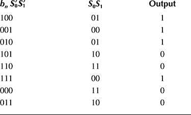
The final logic gate construction for the precoder is as shown in Table 8.1.
8.3.2 Optical MSK Receivers
The optical detection of MSK and nonlinear MSK signals employs a π/2 OPM followed by an optical phase comparator, an MZDI, and then a balanced receiver (BalRx). This detection for optical linear and nonlinear MSK signals is similar to that of the well-known structure MZDI as introduced in Chapter 7 to detect a ±π/2 phase difference of two adjacent bits of the MSK optical sequence.
A new technique for the evaluation of the BERs is implemented. The probability density functions (pdfs) of noise-corrupted received signals after decision sampling are computed with the superposition of a number of weighted Gaussian pdfs. The technique implements the expected maximization theorem and has shown its effectiveness in determining arbitrary distributions [11,12].
8.4 Optical Binary Amplitude MSK Format
8.4.1 Generation
The optical MSK transmitters from [4,13 and 14] can be integrated in the proposed generation of optical MAMSK signals. However, in this chapter, we propose a new simple-in-implementation optical MSK transmitter configuration employing high-speed cascaded E-OPMs as shown in Figure 8.2. E-OPMs and interferometers operating at high frequency using resonant-type electrodes have been studied and proposed in Refs. [7,8]. In addition, high-speed electronic driving circuits evolved with the ASIC technology using 0.1 μm GaAs P-HEMT or InP HEMTs [9] enables the feasibility in realization of the proposed optical MSK transmitter structure. The baseband equivalent optical MSK signal is represented in Equation 8.8.
where ak = ±1 are the logic levels; Ik = ±1 is a clock pulse whose duty cycle is equal to the period of the driving signal Vd(t); fd is the frequency deviation from the optical carrier frequency; and h = 2fdT is defined in Equations 8.2 and 8.3 as the frequency modulation index. In the case of optical MSK, h = 1/2 or fd = 1/(4T).
The first E-OPM enables the frequency modulation of data logic into the USBs and LSBs of the optical carrier with a frequency deviation of fd. Differential phase precoding is not necessary in this configuration owing to the nature of the continuity of the differential phase trellis. By alternating the driving sources Vd(t) with sinusoidal waveforms or a combination of sinusoidal and periodic ramp signals, different schemes of linear and nonlinear phase-shaping MSK-transmitted sequences can be generated [15]. The second E-OPM enforces the phase continuity of the lightwave carrier at every bit transition. The delay control between the E-OPMs is usually implemented by the phase shifter, as shown in Figure 8.2. The driving voltage of the second E-OPM is precoded to fully compensate for the transitional phase jump at the output E01(t) of the first E-OPM. The phase continuity characteristic of the optical MSK signals is determined by the algorithm in Equation 8.2. In order to mitigate the effects of the unstable stages of the rising and falling edges of the electronic circuits, the clock pulse Vc(t) is offset with the driving voltages Vd(t).
The binary amplitude MSK (BAMSK) modulation format is proposed for optical communications. We report numerical results of a 80 Gbps two-bit-per-symbol BAMSK optical system on spectral characteristics and residual dispersion tolerance to different types of fibers. BER of 1e–23 is obtained for 80 Gbps optical BAMSK transmission over 900 km Vascade fiber systems, enabling the feasibility of long-haul transmission for the proposed format.
8.4.2 Optical MSK
MSK, which is well-known in radio frequency and wireless communications, has recently been adapted into optical communications. A few optical MSK transmitter configurations have recently been reported [15,16]. For optically amplified communications systems, if multilevel concepts can be incorporated in those reported schemes, the symbol rate would be reduced, and hence bandwidth efficiency can be achieved. This is the principal motivation for the proposed modulation scheme.
BAMSK is a special case of the M-ary CPM format that enables a binary-level (PAM- or QAM-like) transmission scheme, while the bandwidth efficiency due to transitional phase continuity properties between two consecutive symbols (CPM-like signals) are preserved. The generation of M-ary CPM sequences can be expressed in Equation 8.10 [17]
where
In a generalized M-ary CPM transmitter, values of an and bmn are statistically independent and taken from the set of {±1, ±3,…}. An and Bm are the signal state amplitude levels, which are either in-phase or π phase shift, with the largest level component at the end of the nth symbol interval; q(t) is the pulse-shaping function, and h is the frequency modulation index. In the case of BAMSK, Equations 8.2 and 8.3, which show the constraints of ϕm to maintain the phase continuity characteristic of CPM sequences, are simplified to Equations 8.4 and 8.5, respectively, where h = ½ and the phase-shaping function q(t − nT) is a periodic ramp signal with a duty cycle of 4T.
Any configuration of the reported optical MSK transmitters in Refs. [4,14, 15 and 16] can be utilized in the proposed generation scheme of optical BAMSK signals. Figure 8.1a shows the block structure of the optical BAMSK transmitter in which two optical MSK transmitters are integrated in a parallel configuration. The amplitude levels are determined from Equations 8.1, 8.4, and 8.5 by the splitting ratio at the output of a high-precision power splitter. The logic sequences {±1,..} of an and bn are precoded from the binary logic {0,1} of dn as an = dn – 1 and bn = an(1 − dn − 1/h) [17]. The signal-space trajectories of BAMSK signals are shown in Figure 8.1b.
A simple noncoherent configuration for detection of the optical BAMSK sequences consists of phase and amplitude detections. In the case of BAMSK, that is, n = 2, the system effectively implements two bits per symbol with two amplitude levels. Phase detection is enabled with the employment of the well-known integrated optic phase comparator MZDI-balanced receiver with one-bit time delay on one arm of the MZDI [18]. An additional π/2 phase shift is introduced. Figure 8.8a and b show the block diagram and the eye diagrams of the amplitudes and phases of the optical BAMSK signals, respectively. In phase detection, the decision threshold, which is plotted in broken-line style, is at a zero level, whereas the amplitude levels are determined by different thresholds. A new technique in BER calculation for dispersive and noise-corrupted received signals that exploits the expected maximization (EM) theorem is implemented with superposition of a number of weighted Gaussian probability distribution functions [11,19].
A simple noncoherent configuration for detection of linear and nonlinear optical M-ary MSK sequences consists of phase and amplitude detections that are very well known in the discrete phase shift keying schemes such as DPSK or quadrature DPSK [20]. Phase detection is enabled with the employment of the well-known integrated optic phase comparator MZDI-balanced receiver with a one-bit time delay on one arm of the MZDI. An additional π/2 phase shift is introduced to detect the differential π/2 phase shift difference of two adjacent optical MSK pulses. Figure 8.9a and b show the eye diagrams of the amplitudes and phases of the optical BAMSK-detected signals, respectively. In the case of N = 2 and N = 3, the system effectively implements the two-bits-per-symbol scheme and the three-bits-per-symbol scheme with two and four amplitude levels, respectively. In phase detection, the decision threshold, which is plotted in broken-line style, is at zero level because only in-phase and π differential phases are of interest.

FIGURE 8.8 (a) Block diagram of optical BAMSK transmitter and (b) signal trajectories of optical BAMSK-transmitted signals of multiamplitude MSK.

FIGURE 8.9 Eye diagrams of (a) amplitude and (b) phase detection of optical BAMSK received signals with a normalized amplitude ratio of 0.285/0.715. The decision threshold is shown in broken-line style.
8.5 Numerical Results and Discussion
The state diagram for MSK is shown in Figure 8.10. The continuous wave carrier source is modulated by the two cascaded MZIMs that are driven by a signal sequence which is the output of a broadband amplifier whose input is from the output of the precoder. The arrows indicate continuous increment or decrement of the phase of the carrier. These information-bearing lightwave signals are then propagated along the fiber spans and detected via a photonic phase comparator, the MZDI, and then detected via a balanced receiver. The obtained eye diagram is then statistically analyzed. A more efficient detection scheme using frequency discrimination will be presented in Chapter 8.
8.5.1 Transmission Performance of Linear and Nonlinear Optical MSK Systems
The block diagram of the simulation setup is shown in Figure 8.10. The dispersion tolerance of linear, weakly nonlinear, and strongly nonlinear optical MSK signals is numerically investigated, and the results are shown in Figure 8.11. Among the three types, linear MSK is most tolerant to residual dispersion with a 1 dB eye open penalty at 72 ps/nm/km. Strongly nonlinear MSK suffers a severe penalty when the residual dispersion exceeds 85 ps/nm/km, or equivalently, 5 km standard single-mode fiber (SSMF). Figure 8.12 shows the performance of three types of optical MSK-modulated signals versus the optical signal-to-noise ratio (OSNR) in transmission over 540 km Vascade fibers of optically amplified and fully compensated multispan links (6 spans × 90 km/span). The receiver sensitivity of the differential phase comparison balanced receiver is −24.6 dBm. In Vascade fibers, the dispersion factors of the dispersion-compensating fiber is negatively opposite to that of the transmission fiber, an SSMF, of +17.5 ps/nm/km at 1550 nm wavelength. In addition, the dispersion slopes of these fibers are also matched. An optical amplifier of the EDFA type is placed at the end of the transmission fiber, and another is placed after the DCF so that it would boost the optical power to the right level, which is equal to that of the launched power. An EDFA optical gain of 19 dB and 5 dB ASE noise figure is used. The noise margin reduces greatly after the propagation over 6 × 90 km spans. The effects of positive and negative dispersion mismatch and mid-link nonlinearity on phase evolution are shown in Figure 8.11.
The tolerance of these MSK modulations to nonlinear effects is also studied using transmission models, and the simulation results are shown in Figures 8.11 and 8.12. The input power into the fiber span is varied, whereas the length of transmission link is constant at 180 km. At BER = 1e–9, linear MSK could tolerate an increase of the input launched power up to 10.5 dBm, and weakly nonlinear could tolerate up to 10.2 dBm compared to 9.2 dBm in the case of strongly nonlinear MSK. The nonlinear phase shift is proportional to the input power; therefore, increasing the input power would increase nonlinear phase shift as well. This nonlinear phase shift is observed through the asymmetries in the eye diagram and through the scatter plot, which shows the phases of the in-phase and quadrature components have shifted from the x- and y-axes. The maximum phase shift that could be tolerated is approximately 15° of arc. Although increasing the input power increases the noise margin of the eye diagram, it is paid off by the large distortion at the sampling time, causing the SNR to decrease. Typical eye diagrams under full compensation and after transmission over 540 km Vascade fibers of optically amplified and fully compensated multispan links (6 spans × 90 km/span) are shown in Figure 8.13.
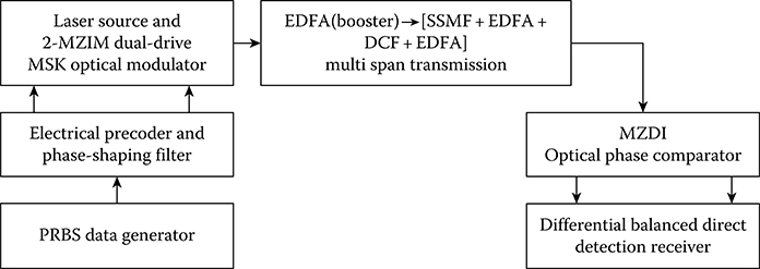
FIGURE 8.10 Schematic diagram of an optically amplified optical transmission system.

FIGURE 8.11 Dispersion tolerance of 40 Gbps linear MSK, weakly nonlinear MSK, and strongly nonlinear MSK optical signals.
We note that if the sampling is conducted at the center of the bit period, then the error is minimum as the ripples of the eyes fall in this position. This is the principal reason why the MSK signals can suffer minimal pulse spreading due to residual and nonlinear phase dispersion. Linear, weakly, and strongly nonlinear MSK phase-shaping functions are investigated. It has been proved that optical MSK is a very efficient modulation scheme that offers excellent performance. With an OSNR of about 17 dB, the BER is obtained to be 1e–9 and reaches 1e–17 for an optical SNR of 19 dB under linear MSK modulation. The modulation formats of linear and nonlinear phase-shaping MSK are also highly resilient to nonlinear effects. Nonlinear distortion appears when the total average power reaches about 9 dBm, that is, about 3–4 dB above that of the NRZ ASK format over a 50-μm-diameter SSMF fiber.
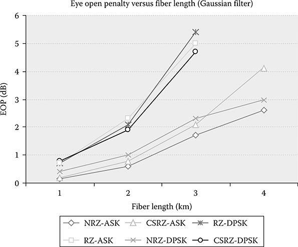
FIGURE 8.12 Simulation of EOP versus transmission distance 1–4 km of SSMF.
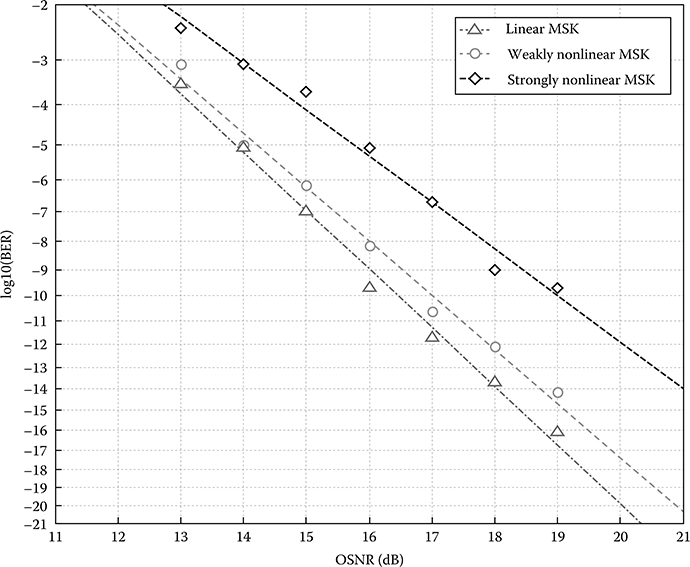
FIGURE 8.13 BER versus optical SNR for transmission of three types of modulated optical MSK signals over 540 km Vascade fibers of optically amplified and fully compensated multispan links (6 spans × 90 km/span).
The nonlinear phase-shaping filters offer better implementation structures in the electronic domain for driving the dual-drive MZIMs than the linear type but suffer some power penalty; however, they are still better than those candidates of other amplitude or phase or differential phase modulation formats.
Weakly nonlinear MSK offers a much lower power penalty and ease of implementation for precoders and phase-shaping filters; thus, it would be the preferred MSK format for long-haul transmission over optically amplified multispan systems. At a BER of 1e–12, linear MSK is 0.3 dB and 1.2 dB more resilient to nonlinear phase effects than weakly nonlinear MSK and strongly nonlinear MSK, respectively. Figure 8.14 depicts the BER versus input power, and the robustness to nonlinearity of linear, weakly nonlinear, and strongly nonlinear optical MSK signals with transmission over 180 km Vascade fibers of two optically amplified and fully compensated span links.

FIGURE 8.14 BER versus input power showing robustness to nonlinearity of linear, weakly nonlinear, and strongly nonlinear optical MSK signals with transmission over 180 km Vascade fibers of two optically amplified and fully compensated span links.
Compared to the DPSK counterpart in 40 Gbps transmission, various types of filtered MSK-modulated signals are more tolerant to residual dispersion. The eye open penalty of 3 dB is obtained at 4 km of SSMF in the case of NRZ-DPSK/ASK or 68 ps/nm, whereas linear MSK can tolerate up to 98 ps/nm or 6 km accordingly.
It is noted that the pulse shaping using the raised-cosine filter offers a better dispersion tolerance and a lower penalty for RZ-DPSK and CSRZ-DPSK after transmitting 3 km. An approximately 2 dB improvement is observed. Thus, pulse shaping compromises the deficits of RZ-pulses owing to a broader spectrum compared to NRZ pulse shapes. We observe no significant improvement in NRZ pulses for both DPSK and ASK signals.
8.5.2 Transmission Performance of Binary Amplitude Optical MSK Systems
Figure 8.15 numerically compares the power spectra of 80 Gbps optical BAMSK and 40 Gbps optical MSK and DPSK signals. The normalized amplitude levels of two optical MSK transmitters take the ratio of 0.715/0.285. In general, the power spectrum of the optical BAMSK format has identical characteristics to that of the MSK format, including a narrow spectral width and highly suppressed side lobe, and it outperforms the DPSK counterpart [21].
Figure 8.16 shows numerical results of residual dispersion tolerance in both amplitude and phase of 80 Gbps optical BAMSK systems with a normalized amplitude ratio of 0.285/0.715. Standard single-mode fibers (SSMF) and Corning LEAF fibers with a dispersion factor of ±17 ps/nm/km and ±4.5 ps/nm/km, respectively, are used. As expected, the severe penalty due to fiber dispersion derives from the distortion of the waveform amplitudes whose values dramatically jumps over a 20 dB penalty compared to 3 dB in the case of phase distortion at 50 ps/nm SMF residual dispersion. The LEAF fiber enables the system tolerance to a residual dispersion of approximately 150 ps/nm for a 3 dB penalty. It should be kept in mind that the optical 80 Gbps system under test has an effective transmission rate of approximately 40 Gbps due to the two-bitper-symbol BAMSK scheme.
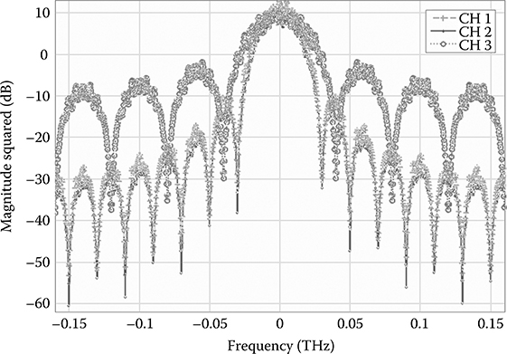
FIGURE 8.15 Comparison of spectra of 80 Gbps optical BAMSK, 40 Gbps optical MSK, and 40 Gbps optical binary DPSK signals.
Figure 8.15 numerically reports the transmission feasibility of 80 Gbps optical BAMSK signals over 900 km Vascade fibers with possible BER values less than 1e–12 for both normalized input amplitude ratios of 0.285/0.715 and 0.25/0.75, respectively. In Figure 8.17, the performance curve with diamond markers and dashed line represents the first ratio, whereas round markers and solid line curves are used for the latter ratio. The single-channel transmission system consists of an 80 Gbps pseudo random generator with a 128-bit sequence, 10 spans of 90 km Vascade fibers (60 km of +17 ps/nm/km and 30 km of −34 ps/nm/km and fully compensated for both chromatic dispersion and dispersion slope), and an optical filter with a bandwidth of 80 GHz. The electronic noise of the receiver is modeled with an equivalent noise current density of the electrical amplifier of 20 pA/(Hz)1/2 and a dark current of 2 × 10 nA (two photodiodes in a balanced receiver structure). This configuration yields the back-to-back receiver sensitivity at BER = 1e–9 to be approximately −23 dBm. The eye diagrams are obtained after fifth-order Bessel electrical filters with a bandwidth of 36 GHz. The launched peak input power is varied from −10 dBm to +3 dBm, whose corresponding average powers range from −12.5 dBm to −0.5 dBm. The phase noise is dominant in the total BER in low average launched input powers (less than −3 dBm). The results raise the necessity of optimizing the amplitude levels for the optimum BER for optical BAMSK signal transmission.

FIGURE 8.16 Numerical results on residual dispersion tolerance of 80 Gbps optical BAMSK systems (effectively 40 Gbps symbol rate) with a normalized amplitude ratio of 0.285/0.715 in both amplitude and phase detection.

FIGURE 8.17 Transmission performance of 80 Gbps optical BAMSK over 900 km Vascade fiber systems in two cases of normalized amplitude ratios: 0.25/0.75 (round markers and solid line) and 0.285/0.715 (diamond markers and dashed line), respectively.
We have proposed, with detailed operational principles, a new configuration of optical MSK transmitter using two cascaded E-OPMs that reduces the complexity of photonic components. These transmitters can be integrated in a parallel configuration for the inaugural proposed generation of optical M-ary MSK signals. The number of signal states can increase with the number of transmitters. The spectral properties of optical M-ary MSK are similar to those of optical MSK and better than the DPSK counterparts. The main source of penalty of fiber residual dispersion is caused by the waveform amplitude distortions, which can be overcome with advanced dispersion equalization techniques. The numerical results of the transmission performance over 900 km Vascade fibers have been presented in two different cases of normalized amplitude ratios of the BAMSK modulation format. A BER of 1e–23 enables the long-haul transmission feasibility of the proposed format. The simulation test bed is successfully developed based on the MATLAB and Simulink platform.
8.6 Concluding Remarks
We have proposed two new schemes of optical MSK generation and detection Ref. [21]. These two optical transmitter configurations can generate linear and various types of nonlinear optical MSK modulation formats. The precoder for the I–Q optical MSK structure is shown. The direct detection of optical lightwave is utilized with implementation of the well-known differential noncoherent balanced receivers. Simulated spectral characteristics and dispersion tolerance to 40 Gbps transmission are presented and compared to those of the ASK and DPSK counterparts.
We have proposed the BAMSK modulation format for optical communications. We have reported the configuration for generation and noncoherent detection of the optical BAMSK sequences. The number of signal states can be easily increased with additional optical MSK transmitters. Spectral properties of the 80 Gbps optical BAMSK are similar to those of the 40 Gbps optical MSK and better than the 40 Gbps optical DPSK counterparts. The main source of penalty in dispersion tolerance is the waveform amplitude distortions, which can be overcome with advanced dispersion equalization techniques. The numerical results of transmission performance for an 80 Gbps optical BAMSK system over 900 km Vascade fibers have been reported. A BER of 1e–23 enables the long-haul transmission feasibility of the proposed format. The simulation test bed is developed on the MATLAB and Simulink platform.
It has been proved that MSK transmitter models for these modulation formats can be implemented using the parallel structure of dual-drive MZIM data modulators. The differences in the implementations of these transmitter models are the pulse-shaping waveforms, in which linear MSK follows a triangular periodic waveform, and weakly nonlinear and strongly nonlinear MSKs have sinusoidal waveforms but differ in their amplitudes. The models are simulated under different conditions to investigate the effects of fiber characteristics such as fiber loss, nonlinear effects, and dispersion on the performance of the models. The rotation of the scatter plots confirms the behavior of MSK-modulated signals due to linear chromatic dispersion and nonlinear phase-shaping effects. The simulated optically amplified distance is 540 km fully compensated SSMF. The linear and nonlinear optical MSK modulation formats can thus be offered as an alternative advanced modulation format for long-haul optically amplified transmission.
The visualization of the evolutions of the MSK signal phasor under self-phase modulation is not fully described in this chapter. An electronic compensation technique can be implemented by design of the pre distorted MSK signals at the input of the shaping filters.
References
1. T. Hoshida, Optimal 40 Gb/s modulation formats for spectrally efficient long haul DWDM systems, IEEE J. Lightwave Technol., Vol. 20, pp. 1989–1996, 2002.
2. Y. Zhu, K. Cordina, N. Jolley, R. Feced, H. Kee, R. Rickard, and A. Hadjifotiou, 1.6 bit/s/Hz orthogonally polarized CSRZ–DQPSK transmission of 8x40 Gbit/s over 320 km NDSF, in OFC’04, Tu-F1, 2004.
3. T. Sakamoto, T. Kawanishi, and M. Izutsu, Initial phase control method for high-speed external modulation in optical minimum-shift keying format, in ECOC’05, Vol. 4, pp. 853–854, 2005.
4. M. Ohm and J. Spiedel, Optical minimum shift keying with direct detection, in Proceedings of the SPIE on Optical Transmission, Switching and Systems, Vol. 5281, pp. 150–161, 2004.
5. T. L. Huynh, L. N. Binh, and K. K. Pang, Optical MSK long-haul transmission systems, in SPIE Proceedings of the APOC’06, paper 6353–86, Thu9a, 2006.
6. T. L. Huynh, L. N. Binh, and K. K. Pang, Linear and weakly nonlinear optical continuous phase modulation formats for high performance DWDM long-haul transmission, in ECOC’06, Cannes, France, 2006.
7. T. Kawanishi, S. Shinada, T. Sakamoto, S. Oikawa, K. Yoshiara, and M. Izutsu, Reciprocating optical modulator with resonant modulating electrode, Electron. Lett., Vol. 41, No. 5, pp. 271–272, 2005.
8. R. Krahenbuhl, J. H. Cole, R. P. Moeller, and M. M. Howerton, High-speed optical modulator in LiNbO3 with cascaded resonant-type electrodes, J. Lightwave Technol., Vol. 24, No. 5, pp. 2184–2189, 2006.
9. I. P. Kaminow and T. Li, Optical Fiber Communications, Vol. IVA, chap. 16, Elsevier Science, San Diego, 2002.
10. F. Amoroso, Pulse and spectrum manipulation in the minimum frequency shift keying (MSK) format, IEEE Trans. Commun., Vol. 24, pp. 381–384, 1976.
11. L. Ding, W. D. Zhong, C. Lu, and Y. Wang, New bit-error-rate monitoring technique based on histograms and curve fitting, Opt. Express., Vol. 12, No. 11, pp. 2507–2511, 2004.
12. I. Shake, H. Takara, and S. Kawanishi, Simple Q factor monitoring for BER estimation using opened eye diagrams captured by high-speed asynchronous, Photon. Technol. Lett., Vol. 15, pp. 620–622, 2003.
13. J. Mo, D. Yi, Y. Wen, S. Takahashi, Y. Wang, and C. Lu, Novel modulation scheme for optical continuous-phase frequency-shift keying, in OFC’ 03, paper OFG2, 2004.
14. J. Mo, D. Yi, Y. Wen, S. Takahashi, Y. Wang, and C. Lu, Optical minimum-shift keying modulator for high spectral efficiency WDM systems, in ECOC’ 05, Vol. 4, pp. 781–782, 2005.
15. T. L. Huynh, L. N. Binh, K. K. Pang, and L. Chan, Photonic MSK transmitter models using linear and non-linear phase shaping for non-coherent long-haul optical transmission, in SPIE Proceedings of the APOC’06, paper 6353–85, September 3–7, 2006.
16. T. Sakamoto, T. Kawanashi, and M. Izutsu, Optical minimum-shift keying with external modulation scheme, Opt. Express, Vol. 13, No. 20, pp. 7741–7747, 2005.
17. J. G. Proakis, Digital Communications, 4th ed., New York: McGraw-Hill, pp. 199–202, chap. 4, 2001.
18. C. Wree, J. Leibrich, J. Eick, W. Rosenkranz, and D. Mohr, Experimental investigation of receiver sensitivity of RZ-DQPSK modulation using balanced detection, in OFC’03, Vol. 2, pp. 456–457, 2003.
19. R. Redner and H. Walker, Mixture densities, maximum likelihood and the EM algorithm, SIAM Rev., Vol. 26, No. 2, pp. 195–239, 1984.
20. K. Sekine, N. Kikuchi, S. Sasaki, S. Hayase, C. Hasegawa, and T. Sugawara, 40 Gbit/s, 16-ary (4bit/symbol) optical modulation/demodulation scheme, Electron. Lett., Vol. 41, No. 7, pp. 430–432, 2005.
21. J. G. Proakis, Digital Communications, 4th ed., New York: McGraw-Hill, pp. 185–213, 2001.