
Gravity Concentration
Gravity concentration is the separation of minerals based upon the difference in density. Techniques of gravity concentration have been around for millennia. Some believe that the legend of the Golden Fleece from Homer’s Odyssey was based upon a method of gold recovery, which was to place an animal hide (such as a sheep’s fleece) in a stream containing alluvial gold; the dense gold particles would become trapped in the fleece and be recovered. In the various gold rushes of the nineteenth century, many prospectors used gold panning as a means to make their fortune—another ancient method of gravity concentration. Gravity concentration, or density-based separation methods, declined in importance in the first half of the twentieth century due to the development of froth flotation, which allowed for the selective treatment of low-grade complex ores. They remain, however, the main concentrating methods for iron and tungsten ores and are used extensively for treating tin ores, coal, gold, beach sands, and many industrial minerals.
Keywords
Principles; gravitational and centrifugal devices; fluidized bed separators; sluices and cones; gravity recoverable gold; dry processing
10.1 Introduction
Gravity concentration is the separation of minerals based upon the difference in density. Techniques of gravity concentration have been around for millennia. Some believe that the legend of the Golden Fleece from Homer’s Odyssey was based upon a method of gold recovery, which was to place an animal hide (such as a sheep’s fleece) in a stream containing alluvial gold; the dense gold particles would become trapped in the fleece and be recovered (Agricola, 1556). In the various gold rushes of the nineteenth century, many prospectors used gold panning as a means to make their fortune—another ancient method of gravity concentration. Gravity concentration, or density-based separation methods, declined in importance in the first half of the twentieth century due to the development of froth flotation (Chapter 12), which allowed for the selective treatment of low-grade complex ores. They remain, however, the main concentrating methods for iron and tungsten ores and are used extensively for treating tin ores, coal, gold, beach sands, and many industrial minerals.
In recent years, mining companies have reevaluated gravity systems due to increasing costs of flotation reagents, the relative simplicity of gravity processes, and the fact that they produce comparatively little environmental impact. Modern gravity techniques have proved efficient for concentration of minerals having particle sizes down to the 50 µm range and, when coupled with improved pumping technology and instrumentation, have been incorporated in high-capacity plants (Holland-Batt, 1998). In many cases a high proportion of the mineral in an ore body can be preconcentrated effectively by gravity separation systems; the amount of reagents and energy used can be cut significantly when the more expensive methods are restricted to the processing of a gravity concentrate. Gravity separation at coarse sizes (as soon as liberation is achieved) can also have significant advantages for later treatment stages, due to decreased surface area, more efficient dewatering, and the absence of adsorbed chemicals, which could interfere with further processing.
10.2 Principles of Gravity Concentration
Gravity concentration methods separate minerals of different specific gravity by their relative movement in response to gravity and one or more other forces, the latter often being the resistance to motion offered by a viscous fluid, such as water or air.
It is essential for effective separation that a marked density difference exists between the mineral and the gangue. Some idea of the type of separation possible can be gained from the concentration criterion, Δρ:
(10.1)
where ρh is the density of the heavy mineral, ρl is the density of the light mineral, and ρf is the density of the fluid medium.
In general terms, if the quotient has a magnitude greater than 2.5, then gravity separation is relatively easy, with the efficiency of separation decreasing as the value of the quotient decreases. To give an example, if gold is being separated from quartz using water as the carrier fluid, the concentration criterion is 11.1 (density of gold being 19,300 kg m−3; quartz being 2,650 kg m−3), which is why panning for gold has been so successful.
The motion of a particle in a fluid is dependent not only on its specific gravity, but also on its size (Chapter 9)—large particles will be affected more than smaller ones. The efficiency of gravity processes therefore increases with particle size, and the particles should be sufficiently coarse to move in accordance with Newton’s law (Eq. (9.8)). Particles small enough that their movement is dominated mainly by surface friction respond relatively poorly to commercial high-capacity gravity methods. In practice, close size control of feeds to gravity processes is required to reduce the size effect and make the relative motion of the particles specific gravity-dependent. The incorporation of enhanced gravity concentrators, which impart additional centrifugal acceleration to the particles (Section 10.4), have been utilized in order to overcome some of the drawbacks of fine particle processing. Table 10.1 gives the relative ease of separating minerals using gravity techniques, based upon the particle size and concentration criterion (Anon., 2011).
Table 10.1
Dependence on Concentration Criterion (Eq. (10.1)) for Separations
| Concentration Criterion | Separation? | Useful for? |
| 2.5 | Relatively easy | To 75 μm |
| 1.75–2.5 | Possible | To 150 μm |
| 1.5–1.75 | Difficult | To 1.7 mm |
| 1.25–1.5 | Very difficult | |
| <1.25 | Not possible |
10.3 Gravitational Concentrators
Many machines have been designed and built to effect separation of minerals by gravity (Burt, 1985). The dense medium separation (DMS) process is used to preconcentrate crushed material prior to grinding and will be considered separately in the next chapter (Chapter 11). Design and optimization of gravity circuits is discussed by Wells (1991) and innovations in gravity separation are reviewed by Honaker et al. (2014).
It is essential for the efficient operation of all gravity separators that the feed is carefully prepared. Grinding is particularly important to provide particles of adequate liberation; successive regrinding of middlings is required in most operations. Primary grinding should be performed where possible in open-circuit rod mills, but if fine grinding is required, closed-circuit ball milling should be used, preferably with screens closing the circuits rather than hydrocyclones, in order to reduce selective overgrinding of heavy friable valuable minerals (see also Chapters 8 and 9). Other methods of comminution, as described in Chapters 6 and 7, such as semi-autogeneous grinding mills and high-pressure grinding rolls, may find application in preparing gravity feeds.
Gravity separators are sensitive to the presence of slimes (ultrafine particles), which increase the viscosity of the slurry and hence reduce the sharpness of separation, and obscure visual cutpoints for operators. It has been common practice to remove particles less than about 10 µm from the feed (i.e., de-slime), and divert this fraction to the tailings, which can incur considerable loss of values. De-sliming is often achieved by the use of hydrocyclones, although hydraulic classifiers may be preferable in some cases since the high shear forces produced in hydrocyclones tend to cause degradation of friable minerals (and create more loss of slimed values).
The feed to jigs and spirals should, if possible, be screened before separation takes place, each fraction being treated separately. In most cases, however, removal of the oversize by screening, in conjunction with de-sliming, is adequate. Processes which employ flowing-film separation, such as shaking tables, should always be preceded by good hydraulic classification in multi-spigot hydrosizers (Chapter 9).
Although most slurry transportation is achieved by centrifugal pumps and pipelines, as much as possible use should be made of natural gravity flow; many old gravity concentrators were built on hillsides to achieve this. Reduction of slurry pumping to a minimum not only lowers energy consumption, but also reduces slimes production in the circuit. To minimize degradation of friable minerals, pumping velocities should be as low as possible, consistent with maintaining the solids in suspension.
One of the most important aspects of gravity circuit operations is correct water balance within the plant. Almost all gravity concentrators have an optimum feed pulp density, and relatively little deviation from this density causes a rapid decline in efficiency. Accurate pulp density control is therefore essential, and this is most important on the raw feed. Automatic density control should be used where possible, and the best way of achieving this is by the use of nucleonic density gauges (Chapter 3) controlling the water addition to the new feed. Although such instrumentation is expensive, it is usually economic in the long term. Control of pulp density within the circuit can be made by the use of settling cones (Chapter 9) preceding the gravity device. These thicken the pulp, but the overflow often contains solids, and should be directed to a central large sump or thickener. For substantial increase in pulp density, hydrocyclones or thickeners may be used. The latter are the more expensive, but produce less particle degradation and also provide substantial surge capacity. It is usually necessary to recycle water in most plants, so adequate thickener or cyclone capacity should be provided, and slimes build-up in the recycled water must be minimized.
If the ore contains an appreciable amount of sulfide minerals then, because they are relatively dense and tend to report with the “heavy” product, they need to be removed. If the primary grind is finer than ca. 300 µm, the sulfides should be removed by froth flotation prior to gravity concentration. If the primary grind is too coarse for effective sulfide flotation, then the gravity concentrate must be reground prior to removal of the sulfides. The sulfide flotation tailing is then usually cleaned by further gravity concentration.
The final gravity concentrate often needs cleaning by magnetic separation, leaching, or some other method, in order to remove certain mineral contaminants. For instance, at the South Crofty tin mine in Cornwall, the gravity concentrate was subjected to cleaning by magnetic separators, which removed wolframite from the cassiterite product.
10.3.1 Jigs
Jigging is one of the oldest methods of gravity concentration, yet the basic principles have only recently been understood. A mathematical model developed by Jonkers et al. (2002) predicts jig performance on a size-by-density basis; Mishra and Mehrotra (1998) developed discrete element method models of particle motion in a jig; and Mishra and Mehrotra (2001) and Xia et al. (2007) have developed a computational fluid dynamics model of coal stratification in a jig.
In the jig, the separation of minerals of different specific gravity is accomplished in a particle bed, which is fluidized by a pulsating current of water, producing stratification based upon density. The bed may be a specific mineral added to and retained in the jig, called ragging, composed of a certain density and shape through which the dense particles penetrate and the light particles pass over the top. The aim is to dilate the bed and to control the dilation so that the heavier, smaller particles penetrate the interstices of the bed and the larger high-specific gravity particles fall under a condition similar to hindered settling (Lyman, 1992).
On the pulsion stroke the bed is normally lifted as a mass, then as the velocity decreases it tends to dilate, the bottom particles falling first until the whole bed is loosened. On the suction stroke it then closes slowly again, and this is repeated at every stroke. Fine particles tend to pass through the interstices after the large ones have become immobile. The motion can be obtained either by using a fixed sieve jig, and pulsating the water, or by employing a moving sieve, as in the simple hand-jig shown in Figure 10.1.

The jig is normally used to concentrate relatively coarse material and, if the feed is fairly close-sized (e.g., 3–10 mm), it is not difficult to achieve good separation of a fairly narrow specific gravity range in minerals in the feed (e.g., fluorite, s.g. 3.2, from quartz, s.g. 2.7). When the specific gravity difference is large, good concentration is possible with a wider size range. Many large jig circuits are still operated in coal, cassiterite, tungsten, gold, barytes, and iron ore concentrators. They have a relatively high unit capacity on classified feed and can achieve good recovery of values down to 150 µm and acceptable recoveries often down to 75 µm. High proportions of fine sand and slime interfere with performance and the fines content should be controlled to provide optimum bed conditions.
Jigging Action
It was shown in Chapter 9 that the equation of motion of a particle settling in a viscous fluid is:
(10.2)
where m is the mass of the mineral particle, dx/dt is the acceleration, g is the acceleration due to gravity, m′ is the mass of displaced fluid, and D is the fluid resistance due to the particle movement.
At the beginning of the particle movement, since the velocity x is very small, D can be ignored, as it is a function of velocity.
Therefore
(10.3)
and since the particle and the displaced fluid are of equal volume,
(10.4)
where ρs and ρf are the respective densities of the solid and the fluid.
The initial acceleration of the mineral grains is thus independent of size and dependent only on the densities of the solid and the fluid. Theoretically, if the duration of fall is short enough and the repetition of fall frequent enough, the total distance travelled by the particles will be affected more by the differential initial acceleration, and therefore by density, than by their terminal velocities, and therefore by size. In other words, to separate small heavy mineral particles from large light particles, a short jigging cycle is necessary. Although relatively short, fast strokes are used to separate fine minerals, more control and better stratification can be achieved by using longer, slower strokes, especially with the coarser particle sizes. It is therefore good practice to screen the feed to jigs into different size ranges and treat these separately. The effect of differential initial acceleration is shown in Figure 10.2.

If the mineral particles are examined after a longer time, they will have attained their terminal velocities and will be moving at a rate dependent on their specific gravity and size. Since the bed is really a loosely packed mass with interstitial water providing a very thick suspension of high density, hindered-settling conditions prevail, and the settling ratio of heavy to light minerals is higher than that for free settling (Chapter 9). Figure 10.3 shows the effect of hindered settling on the separation.

The upward flow can be adjusted so that it overcomes the downward velocity of the fine light particles and carries them away, thus achieving separation. It can be increased further so that only large heavy particles settle, but it is apparent that it will not be possible to separate the small heavy and large light particles of similar terminal velocity.
Hindered settling has a marked effect on the separation of coarse minerals, for which longer, slower strokes should be used, although in practice, with coarser feeds, it is unlikely that the larger particles have sufficient time to reach their terminal velocities.
At the end of a pulsion stroke, as the bed begins to compact, the larger particles interlock, with the smaller particles still moving downward through the interstices under the influence of gravity. The fine particles may not settle as rapidly during this consolidation trickling phase (Figure 10.4) as during the initial acceleration or suspension, but if consolidation trickling can be made to last long enough, the effect, especially in the recovery of the fine heavy minerals, can be considerable.
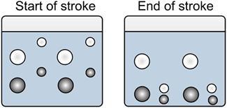
Figure 10.5 shows an idealized jigging process by the described phenomena.

In the jig the pulsating water currents are caused by a piston having a movement that is a harmonic waveform (Figure 10.6). The vertical speed of flow through the bed is proportional to the speed of the piston. When this speed is greatest, the speed of flow through the bed is also greatest (Figure 10.7).


The upward speed of flow increases after point A, the beginning of the cycle. As the speed increases, the particles will be loosened and the bed will be forced open, or dilated. At, say, point B, the particles are in the phase of hindered settling in an upward flow, and since the speed of flow from B to C still increases, the fine particles are pushed upward by the flow. The chance of them being carried along with the top flow into the low-density product (often the tailings) is then at its greatest. In the vicinity of D, first the coarser particles and later the remaining fine particles will fall back. Due to the combination of initial acceleration and hindered settling, it is mainly the coarser particles that will lie at the bottom of the bed.
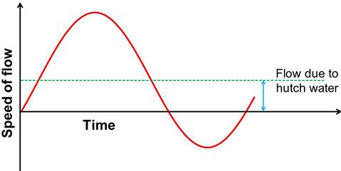
At E, the point of transition between the pulsion and the suction stroke, the bed will be compacted. Consolidation trickling can now occur to a limited extent. In a closely sized ore, the heavy particles can now penetrate only with difficulty through the bed and may be lost to the low-density stream. Severe compaction of the bed can be reduced by the addition of hutch water, a constant volume of water, which creates a constant upward flow through the bed. This flow, coupled with the varying flow caused by the piston, is shown in Figure 10.8. Thus suction is reduced by hutch-water addition and is reduced in duration; by adding a large quantity of water, the suction may be entirely eliminated. The coarse ore then penetrates the bed more easily and the horizontal transport of the feed over the jig is also improved. However, fines losses will increase, partly because of the longer duration of the pulsion stroke, and partly because the added water increases the speed of the top flow.
Types of Jig
Essentially, the jig is an open tank filled with water, with a horizontal jig screen at the top supporting the jig bed, and provided with a spigot in the bottom, or hutch compartment, for “heavies” removal (Figure 10.9). Current types of jig are reviewed by Cope (2000). The jig bed consists of a layer of coarse, heavy particles, the ragging, placed on the jig screen on to which the slurry is fed. The feed flows across the ragging and the separation takes place in the jig bed (i.e., in the ragging), so that particles with a high specific gravity penetrate through the ragging and then pass the screen to be drawn off as the heavy product, while the light particles are carried away by the cross-flow to form the light product. The type of ragging material, particle density, size, and shape, are important factors. The harmonic motion produced by the eccentric drive is supplemented by a large amount of continuously supplied hutch water, which enhances the upward and diminishes the downward velocity of the water (Figure 10.8). The combination of actions produces the segregation depicted in Figure 10.10.


One of the oldest types is the Harz jig (Figure 10.11) in which the plunger moves up and down vertically in a separate compartment. Up to four successive compartments are placed in series in the hutch. A high-grade heavy product is produced in the first compartment, successively lower grades being produced in the other compartments, and the light product overflowing the final compartment. If the feed particles are larger than the apertures of the screen, jigging “over the screen” is used, and the concentrate grade is partly governed by the thickness of the bottom layer, determined by the rate of withdrawal through the concentrate discharge port.

The Denver mineral jig (Figure 10.12) is widely used, especially for removing heavy minerals from closed grinding circuits, thus preventing over-grinding (Chapters 7 and 9). The rotary water valve can be adjusted so as to open at any desired part of the jig cycle, synchronization between the valve and the plungers being achieved by a rubber timing belt. By suitable adjustment of the valve, any desired variation can be achieved, from complete neutralization of the suction stroke with hydraulic water to a full balance between suction and pulsion.

Conventional mineral jigs consist of square or rectangular tanks, sometimes combined to form two, three, or four cells in series. In order to compensate for the increase in cross-flow velocity over the jig bed, caused by the addition of hutch water, trapezoidal-shaped jigs were developed. By arranging these as sectors of a circle, the modular circular, or radial, jig was introduced, in which the feed enters in the center and flows radially over the jig bed (and thus the cross-flow velocity is decreasing) toward the light product discharge at the circumference (Figure 10.13).

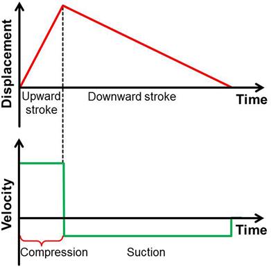
The advantage of the circular jig is its large capacity. Since their development in 1970, IHC Radial Jigs were installed on most newly built tin dredges in Malaysia and Thailand. In the IHC jig, the harmonic motion of the conventional eccentric-driven jig is replaced by an asymmetrical “saw-tooth” movement of the diaphragm, with a rapid upward, followed by a slow downward, stroke (Figure 10.14). This produces a much larger and more constant suction stroke, giving the finer particles more time to settle in the bed, thus reducing their loss to tailings, the jig being capable of accepting particles as fine as 60 μm.
The InLine Pressure Jig (IPJ) is a development in jig technology that has found a wide application for the recovery of free gold, sulfides, native copper, tin/tantalum, diamonds, and other minerals (Figure 10.15). The IPJ is unique in that it is fully encapsulated and pressurized, allowing it to be completely filled with slurry (Gray, 1997). It combines a circular bed with a vertically pulsed screen. Length of stroke and pulsation frequency, as well as screen aperture, can all be altered to suit the application. IPJs are typically installed in grinding circuits, where their low water requirements allow operators to treat the full circulating load, maximizing recovery of liberated values. Both heavy and light products are discharged under pressure.

Jigs are widely used in coal cleaning (also referred to as “coal washing”) and are preferred to the more expensive DMS when the coal has relatively little middlings, or “near-gravity” material. No feed preparation is required, as is necessary with DMS, and for coals that are easily washed, that is, those consisting predominantly of liberated coal and denser “rock” particles, the lack of close density control is not a disadvantage.
Two types of air-pulsated jig—Baum and Batac—are used in the coal industry. The standard Baum jig (Figure 10.16), with some design modifications (Green, 1984), has been used for nearly 100 years and is still the dominant device.

Air under pressure is forced into a large air chamber on one side of the jig vessel, causing pulsation and suction to the jig water, which in turn causes pulsation and suction through the screen plates upon which the raw coal is fed, thus causing stratification. Various methods are used to continuously separate the refuse (heavy non-coal matter) from the lighter coal product, and all the modern Baum jigs are fitted with some form of automatic refuse extraction. One form of control incorporates a float immersed in the bed of material. The float is suitably weighted to settle on the dense layer of refuse moving across the screen plates. An increase in the depth of refuse raises the float, which automatically controls the refuse discharge, either by adjusting the height of a moving gate, or by controlling the pulsating water, which lifts the rejects over a fixed weir plate (Wallace, 1979). This system is reported to respond quickly and accurately.
It is now commonplace for an automatic control system to determine the variations in refuse bed thickness by measuring the differences in water pressure under the screen plates arising from the resistance offered to pulsation. The JigScan control system (developed at the Julius Kruttschnitt Mineral Research Centre) measures bed conditions and pulse velocity many times within the pulse using pressure sensing and nucleonic technology (Loveday and Jonkers, 2002). Evidence of a change in the pulse is an indicator of a problem, allowing the operator to take corrective action. Increased yields of greater than 2% have been reported for JigScan-controlled jigs.
In many situations, the Baum jig still performs satisfactorily, with its ability to handle large tonnages (up to 1,000 t h−1) of coal of a wide size range. However, the distribution of the stratification force, being on one side of the jig, tends to cause unequal force along the width of jig screen and therefore uneven stratification and some loss in the efficiency of separation of the coal from its heavier impurities. This tendency is not so important in relatively narrow jigs, and in the United States multiple float and gate mechanisms have been used to counteract the effects.
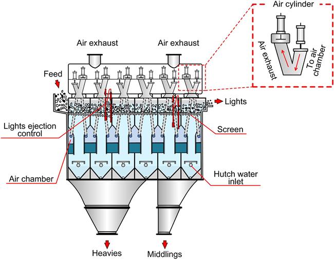
The Batac jig (Zimmerman, 1975) is also pneumatically operated (Figure 10.17), but has no side air chamber like the Baum jig. Instead, it is designed with a series of multiple air chambers, usually two to a cell, extending under the jig for its full width, thus giving uniform air distribution. The jig uses electronically controlled air valves which provide a sharp cutoff of the air input and exhaust. Both inlet and outlet valves are infinitely variable with regard to speed and length of stroke, allowing for the desired variation in pulsation and suction by which proper stratification of the bed may be achieved for differing raw coal characteristics. As a result, the Batac jig can wash both coarse and fine sizes well (Chen, 1980). The jig has also been used to produce high-grade lump ore and sinter-feed concentrates from iron ore deposits that cannot be upgraded by heavy-medium techniques (Miller, 1991).
10.3.2 Spirals
Spiral concentrators have found many varied applications in mineral processing, but perhaps their most extensive application has been in the treatment of heavy mineral sand deposits, such as those carrying ilmenite, rutile, zircon, and monazite, and in recent years in the recovery of fine coal.
The Humphreys spiral was introduced in 1943, its first commercial use being on chrome-bearing sands. It is composed of a helical conduit of modified semicircular cross section. Feed pulp of between 15% and 45% solids by weight and in the size range from 3 mm to 75 µm is introduced at the top of the spiral. As it flows spirally downward, the particles stratify due to the combined effect of centrifugal force, the differential settling rates of the particles, and the effect of interstitial trickling through the flowing particle bed. The result of this action is depicted in Figure 10.18. Figure 10.19 shows the stratification across a spiral trough, with the darker heavy mineral toward the center, with the band becoming increasingly lighter radially where the less dense material flows.


These mechanisms are complex, being much influenced by the slurry density and particle size. Mills (1980) reported that the main separation effect is due to hindered settling, with the largest, densest particles reporting preferentially to the band that forms along the inner edge of the stream. Bonsu (1983), however, reported that the net effect is reverse classification, the smaller, denser particles preferentially entering this band.
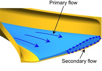
Determination of size-by-size recovery curves of spiral concentrators has shown that both fine and coarse dense particles are lost to the light product, the loss of coarse particles being attributed to the Bagnold force (Bazin et al., 2014). Some of the complexities of the spiral concentrator operation arise from the fact that there is not one flow pattern, but rather two: a primary flow down the spiral and a secondary flow across the trough flowing outward at the top of the stream and inward at the bottom (Figure 10.20) (Holland-Batt and Holtham, 1991).
Ports for the removal of the higher specific gravity particles are located at the lowest points in the cross section. Wash water is added at the inner edge of the stream and flows outwardly across the concentrate band to aid in flushing out entrapped light particles. Adjustable splitters control the width of the heavy product band removed at the ports. The heavy product taken via descending ports is of a progressively decreasing grade, with the light product discharged from the lower end of the spiral. Splitters at the end of the spiral are often used to give three products: heavies, lights, and middlings, giving possibilities for recycle and retreatment in other spirals (e.g., rougher-cleaner spiral combination) or to feed other separation units. Incorporating automatic control of splitter position is being developed (Zhang et al., 2012).
Until the last 20 years or so, all spirals were quite similar, based on the original Humphreys design. Today there is a wide range of designs available. Two developments have been spirals with only one heavy product take-off port at the bottom of the spiral, and the elimination of wash water. Wash waterless-spirals reportedly offer lower cost, easier operation, and simplified maintenance, and have been installed at several gold and tin processing plants.
Another development, double-start spiral concentrators with two spirals integrated around a common column, have effectively doubled the capacity per unit of floor space (Figure 10.21). At Mount Wright in Canada, 4,300 double-start spirals have been used to upgrade specular hematite ore at 6,900 t h−1 at 86% recovery (Hyma and Meech, 1989). Figure 10.22 shows an installation of double-start spirals.


One of the most important developments in fine coal washing was the introduction in the 1980s of spiral separators specifically designed for coal. It is common practice to separate coal down to 0.5 mm using dense medium cyclones (Chapter 11), and below this by froth flotation. Spiral circuits have been installed to process the size range that is least effectively treated by these two methods, typically 0.1–2 mm (Honaker et al., 2008).
A notable innovation in fine coal processing is the incorporation of multistage separators and circuitry, specifically recycling middling streams (Luttrell, 2014). Both theoretical and field studies have shown that single-stage spirals have relatively poor separation efficiencies, as a compromise has to be made to either discard middlings and sacrifice coal yield or accept some middlings and a lower quality coal product. To address this, two-stage compound spirals have been designed in which clean coal and middlings are retreated in a second stage of spirals and the middlings from this spiral are recycled to the first spiral. This is essentially a rougher-cleaner closed-circuit configuration and it can be shown that his will give a higher separation efficiency than a single-stage separator (Section 10.8). The separation efficiencies achievable rival those of dense medium separators.
Some of the developments in spiral technology are the result of modeling efforts. Davies et al. (1991) reviewed the development of spiral models and described the mechanism of separation and the effects of operating parameters. A semi-empirical mathematical model of the spiral has been developed by Holland-Batt (1989). Holland-Batt (1995) discussed design aspects, such as the pitch of the trough and the trough shape. A detailed CFD model of fluid flow in a spiral has been developed and validated by Matthews et al. (1998). In Chapter 17, an example of particle tracking along a spiral used to verify model predictions is illustrated.
Spirals are made with slopes of varying steepness, the angle depending on the specific gravity of separation. Shallow angles are used, for example, to separate coal from shale, while steeper angles are used for heavy mineral–quartz separations. The steepest angles are used to separate heavy minerals from heavy waste minerals, for example, zircon (s.g. 4.7) from kyanite and staurolite (s.g. 3.6). Capacity ranges from 1 to 3 t h−1 on low slope spirals to about double this for the steeper units. Spiral length is usually five or more turns for roughing duty and three turns in some cleaning units. Because treatment by spiral separators involves a multiplicity of units, the separation efficiency is very sensitive to the pulp distribution system employed. Lack of uniformity in feeding results in substantial falls in operating efficiency and can lead to severe losses in recovery. This is especially true with coal spirals (Holland-Batt, 1994).
10.3.3 Shaking Tables
When a film of water flows over a flat, inclined surface, the water closest to the surface is retarded by the friction of the water absorbed on the surface and the velocity increases toward the water surface. If mineral particles are introduced into the film, small particles will not move as rapidly as large particles, since they will be submerged in the slower-moving portion of the film. Particles of high specific gravity will move more slowly than lighter particles, and so a lateral displacement of the material will be produced (Figure 10.23).

The flowing film effectively separates coarse light particles from small dense particles, and this mechanism is exploited to some extent in the shaking-table concentrator (Figure 10.24), which is perhaps the most metallurgically efficient form of gravity concentrator, being used to treat small, more difficult flow-streams, and to produce finished concentrates from the products of other forms of gravity system.

The shaking table consists of a slightly inclined deck, on to which feed, at about 25% solids by weight, is introduced at the feed box and is distributed across the table by the combination of table motion and flow of water (wash water). Wash water is distributed along the length of the feed side, and the table is vibrated longitudinally, using a slow forward stroke and a rapid return, which causes the mineral particles to “crawl” along the deck parallel to the direction of motion. The minerals are thus subjected to two forces, that due to the table motion and that, at right angles to it, due to the flowing film of water. The net effect is that the particles move diagonally across the deck from the feed end and, since the effect of the flowing film depends on the size and density of the particles, they will fan out on the table, the smaller, denser particles riding highest toward the concentrate launder at the far end, while the larger lighter particles are washed into the tailings launder, which runs along the length of the table. An adjustable splitter at the concentrate end is often used to separate this product into two fractions—a high-grade concentrate (heavy product) and a middlings fraction.
Although true flowing film concentration requires a single layer of feed, in practice, a multilayered feed is introduced onto the table, enabling much larger tonnages to be processed. Vertical stratification due to shaking action takes place behind the riffles, which generally run parallel with the long axis of the table and are tapered from a maximum height on the feed side, till they die out near the opposite side, part of which is left smooth. In the protected pockets behind the riffles, the particles stratify so that the finest and heaviest particles are at the bottom and the coarsest and lightest particles are at the top (Figure 10.25). Layers of particles are moved across the riffles by the crowding action of new feed and by the flowing film of wash water. Due to the taper of the riffles, progressively finer sized and higher density particles are continuously being brought into contact with the flowing film of water that tops the riffles. Final concentration takes place at the unriffled area at the end of the deck, where the layer of material is at this stage usually only one or two particles deep.

The significance of the many design and operating variables and their interactions have been reviewed by Sivamohan and Forssberg (1985a), and the development of a mathematical model of a shaking table is described by Manser et al. (1991). The separation on a shaking table is controlled by a number of operating variables, such as wash water, feed pulp density, deck slope, amplitude, and feed rate, and the importance of these variables in the model development is discussed.
Other factors, including particle shape and the type of deck, play an important part in table separations. Flat particles, such as mica, although light, do not roll easily across the deck in the water film; such particles cling to the deck and are carried down to the concentrate discharge. Likewise, spherical dense particles may move easily in the film toward the tailings launder.
The table decks are usually constructed of wood, lined with materials with a high coefficient of friction, such as linoleum, rubber, and plastics. Decks made from fibreglass are also used which, although more expensive, are extremely hard wearing. The riffles on such decks are incorporated as part of the mold.
Particle size plays an important role in table separations; as the range of sizes in a table feed increases, the efficiency of separation decreases. If a table feed is made up of a wide range of particle sizes, some of these sizes will be cleaned inefficiently. The middlings produced may not be “true middlings,” that is, locked particles of associated mineral and gangue, but relatively coarse dense particles and fine light particles. If these particles are returned to the grinding circuit, together with the true middlings, then they will be needlessly reground.
Since the shaking table effectively separates coarse light from fine dense particles, it is common practice to classify the feed, since classifiers put such particles into the same product, on the basis of their equal settling rates. In order to feed as narrow a size range as possible onto the table, classification is usually performed in multi-spigot hydrosizers (Chapter 9), each spigot product, comprising a narrow range of equally settling particles, being fed to a separate set of shaking tables. A typical gravity concentrator employing shaking tables may have an initial grind in rod mills to liberate as much mineral at as coarse a size as possible to aid separation, with middlings being reground before returning to the hydrosizer. Tables operating on feed sizes in the range 3 mm to 100 µm are sometimes referred to as sand tables, and the hydrosizer overflow, consisting primarily of particles finer than 100 µm, is usually thickened and then distributed to tables whose decks have a series of planes, rather than riffles, and are designated slime tables.
Dewatering of the hydrosizer overflow is often performed by hydrocyclones, which also remove particles in the overflow smaller than about 10 µm, which will not separate efficiently by gravity methods due to their extremely slow settling rates.
Successive stages of regrinding are a feature of many gravity concentrators. The mineral is separated at all stages in as coarse a state as possible in order to achieve reasonably fast separation and hence high throughputs.
The capacity of a table varies according to size of feed particles and the concentration criteria. Tables can handle up to 2 t h−1 of 1.5 mm sand and perhaps 1 t h−1 of fine sand. On 100–150 µm feed materials, table capacities may be as low as 0.5 t h−1. On coal feeds, however, which are often tabled at sizes of up to 15 mm, much higher capacities are common. A normal 5 mm raw coal feed can be tabled with high efficiency at 12.5 t h−1 per deck, while tonnages as high as 15 t h−1 per deck are not uncommon when the feed top size is 15 mm. The introduction of double and triple-deck units has improved the area/capacity ratio at the expense of some flexibility and control.
Separation can be influenced by the length of stroke, which can be altered by means of a hand-wheel on the vibrator, or head motion, and by the reciprocating speed. The length of stroke usually varies within the range of 10–25 mm or more, the speed being in the range 240–325 strokes per minute. Generally, a fine feed requires a higher speed and shorter stroke that increases in speed as it goes forward until it is jerked to a halt before being sharply reversed, allowing the particles to slide forward during most of the backward stroke due to their built-up momentum.
The quantity of water used in the feed pulp varies, but for ore-tables normal feed dilution is 20–25% solids by weight, while for coal tables pulps of 33–40% solids are used. In addition to the water in the feed pulp, clear water flows over the table for final concentrate cleaning. This varies from a few liters to almost 100 L min−1 according to the nature of the feed material.
Tables slope from the feed to the tailings (light product) discharge side and the correct angle of incline is obtained by means of a handwheel. In most cases the line of separation is clearly visible on the table, so this adjustment is easily made.
The table is slightly elevated along the line of motion from the feed end to the concentrate end. The moderate slope, which the high-density particles climb more readily than the low-density minerals, greatly improves the separation, allowing much sharper cuts to be made between concentrate, middlings, and tailings. The correct amount of end elevation varies with feed size and is greatest for the coarsest and highest specific gravity feeds. The end elevation should never be less than the taper of the riffles, otherwise there is a tendency for water to flow out toward the riffle tips rather than across the riffles. Normal end elevations in ore tabling range from a maximum of 90 mm for a very heavy, coarse sand, to as little as 6 mm for an extremely fine feed.
Ore-concentrating tables are used primarily for the concentration of minerals of tin, iron, tungsten, tantalum, mica, barium, titanium, zirconium, and, to a lesser extent, gold, silver, thorium, and uranium. Tables are now being used in the recycling of electronic scrap to recover precious metals.
Duplex Concentrator
This machine was originally developed for the recovery of tin from low-grade feeds, but has a wider application in the recovery of tungsten, tantalum, gold, chromite, and platinum from fine feeds (Pearl et al., 1991). Two decks are used alternately to provide continuous feeding, the feed slurry being fed onto one of the decks, the lower density minerals running off into the discharge launder, while the heavy minerals remain on the deck. The deck is washed with water after a preset time, in order to remove the gangue minerals, after which the deck is tilted and the concentrate is washed off. One table is always concentrating, while the other is being washed or is discharging concentrates. The concentrator has a capacity of up to 5 t h−1 of −100 µm feed producing enrichment ratios of between 20 and 500 and is available with various sizes and numbers of decks.
Mozley Laboratory Separator
This flowing film device, which uses orbital shear, is now used in many mineral processing laboratories and is designed to treat small samples (100 g) of ore, allowing a relatively unskilled operator to obtain information for a recovery grade curve within a very short time (Anon., 1980).
10.4 Centrifugal Concentrators
In an attempt to recover fine particles using gravity concentration methods, devices have been developed to make use of centrifugal force. The ability to change the apparent gravitational field is a major departure in the recovery of fine minerals.
Kelsey Centrifugal Jig
The Kelsey centrifugal jig (KCJ) takes a conventional jig and spins it in a centrifuge. The main operating variables adjusted to control processing different types of feed are: centrifugal acceleration, ragging material, and feed size distribution. The 16 hutch J1800 KCJ can treat over 100 t h−1, depending on the application. The use of a J650 KCJ in tin recovery is described by Beniuk et al. (1994).
Other non-jig centrifugal separators have also been developed. An applied gravitational acceleration, such as that imparted by a rapidly rotating bowl, will increase the force on fine particles, allowing for easier separation based upon differences in density. Exploiting this principle, enhanced gravity, or centrifugal, concentrators were developed initially to process fine gold ores but now are applied to other minerals.
Knelson Concentrator
This is a compact batch centrifugal separator with an active fluidized bed to capture heavy minerals (Knelson, 1992; Knelson and Jones, 1994) (Figure 10.26). A centrifugal force up to 60 times that of gravity acts on the particles, trapping denser particles in a series of rings (riffles) located in the machine, while the low-density particles are flushed out. Unit capacities range from laboratory scale to 150 t h−1 for particles ranging in size from 10 μm to a maximum of 6 mm. It is generally used for feeds in which the dense component to be recovered is a very small fraction of the total material, less than 500 g t−1 (0.05% by weight).

Feed slurry is introduced through a stationary feed tube and into the concentrate cone. When the slurry reaches the bottom of the cone it is forced outward and up the cone wall under the influence of centrifugal force. Fluidization water is introduced into the concentrate cone through a series of fluidization holes (see inset in Figure 10.26). The slurry fills each ring to capacity to create a concentrating bed, with compaction of the bed prevented by the fluidization water. The flow of water that is injected into the rings is controlled to achieve optimum bed fluidization. High-specific gravity particles are captured and retained in the concentrating cone; the high-density material may also substitute for the low-density material that was previously in the riffles—made possible by the fluidization of the bed. When the concentrate cycle is complete, concentrates are flushed from the cone into the concentrate launder. Under normal operating conditions, this automated procedure is achieved in less than 2 min in a secure environment.
The units have seen a steady improvement in design from the original Manual Discharge (MD), to Centre-Discharge (CD), to Extended Duty (XD), and the Quantum Series. The first installation was in the grinding circuit at Camchib Mine, Chibougamau, Quebec, Canada, in 1987 (Nesset, 2011).
Falcon Concentrator
Another spinning batch concentrator (Figure 10.27), it is designed principally for the recovery of free gold in grinding circuit classifier underflows where, again, a very small (<1%) mass pull to concentrate is required. The feed first flows up the sides of a cone-shaped bowl, where it stratifies according to particle density before passing over a concentrate bed fluidized from behind by back-pressure (process) water. The bed retains dense particles such as gold, and lighter gangue particles are washed over the top. Periodically the feed is stopped, the bed rinsed to remove any remaining lights and is then flushed out as the heavy product. Rinsing/flushing frequency, which is under automatic control, is determined from grade and recovery requirements.

The units come in several designs, the Semi-Batch (SB), Ultrafine (UF), and i-Con, designed for small scale and artisanal miners. The first installation was at the Blackdome Gold Mine, British Columbia, Canada, in 1986 (Nesset, 2011).
These two batch centrifugal concentrators have been widely applied in the recovery of gold, platinum, silver, mercury, and native copper; continuous versions are also operational, the Knelson Continuous Variable Discharge (CVD) and the Falcon Continuous (C) (Klein et al., 2010; Nesset, 2011).
Multi-Gravity Separator
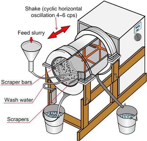
The principle of the multi-gravity separator (MGS) can be visualized as rolling the horizontal surface of a conventional shaking table into a drum, then rotating it so that many times the normal gravitational pull can be exerted on the mineral particles as they flow in the water layer across the surface. Figure 10.28 shows a cross section of the pilot scale MGS. The Mine Scale MGS consists of two slightly tapered open-ended drums, mounted “back to back,” rotating at speeds variable between 90 and 150 rpm, enabling forces of between 5 and 15 G to be generated at the drum surfaces. A sinusoidal shake with an amplitude variable between 4 and 6 cps is superimposed on the motion of the drum, the shake imparted to one drum being balanced by the shake imparted to the other, thus balancing the whole machine. A scraper assembly is mounted within each drum on a separate concentric shaft, driven slightly faster than the drum but in the same direction. This scrapes the settled solids up the slope of the drum, during which time they are subjected to counter-current washing before being discharged as concentrate at the open, outer, narrow end of the drum. The lower density minerals, along with the majority of the wash water, flow downstream to discharge via slots at the inner end of each drum. The MGS has been used to effect improvements in final tin concentrate grade (Turner and Hallewell, 1993).
Testing for Gravity Recoverable Gold
Although most of the gold from gold mines worldwide is recovered by dissolution in cyanide solution, a proportion of coarse (+75 µm) gold is recovered by gravity separators. It has been argued that separate treatment of the coarse gold in this way constitutes a security risk and increases costs. Gravity concentration can remain an attractive option only if it can be implemented with low capital and operating costs. A test using a laboratory centrifugal concentrator designed to characterize the gravity recoverable gold (GRG) has been described by Laplante et al. (1995), and recently reviewed by Nesset (2011). The GRG test has become a standard method for determining how much of the gold in an ore can be recovered by gravity, often through employing a centrifugal separator. The procedure for undertaking a GRG test is shown in Figure 10.29. The sieved fractions are assayed for gold and cumulative gold recovery as a function of particle size determined (GRG response curves).

The results of a GRG test do not directly indicate what the gravity recovery of an installed circuit would be. The GRG test aims to quantify the ore characteristics only. In practice, plant recoveries in a gravity circuit have been found to vary from 20% to 90% of the GRG test value. The test is now applied to other high-value dense minerals such as platinum group minerals.
Often, the gravity concentrator unit will be placed inside the closed grinding circuit, treating the hydrocyclone underflow (Chapter 7). Using GRG results, it is possible to simulate recovery by a gravity separation device, which can be used to decide on the installation and how much of the underflow to treat. In certain cases where sulfide minerals are the gravity gold carrier, flash flotation combined with gravity concentration technology provides the most effective gold recovery (Laplante and Dunne, 2002).
10.5 Sluices and Cones
Sluices
Pinched sluices of various forms have been used for heavy mineral separations for centuries and are familiar in many western movies. In its simplest form (Figure 10.30), it is an inclined launder about 1 m long, narrowing from about 200 mm in width at the feed end to about 25 mm at the discharge. Pulp of between 50% and 65% solids by weight is fed with minimal turbulence and stratifies as it descends; at the discharge end these strata are separated by various means, such as by splitters, or by some type of tray (Sivamohan and Forssberg, 1985b). The fundamental basis for gravity concentration in sluices is described by Schubert (1995). The simple sluice box can be a relatively efficient gravity concentrator, provided it is correctly operated. A recent episode on the Discovery Channel showed the use of sluices in gold processing.

Reichert Cone
The Reichert cone is a wet gravity concentrating device that was designed for high-capacity applications in the early 1960s, primarily to treat titanium-bearing beach sands (Ferree, 1993). Its principle of operation is similar to the pinched sluice. Figure 10.31 shows a schematic of a Reichert cone, with the feed pulp being distributed evenly around the periphery of the cone. As it flows toward the center of the cone the heavy particles separate to the bottom of the film. A slot in the bottom of the concentrating cone removes this heavy product (usually the concentrate); the part of the film flowing over the slot is the light product (tailings). The efficiency of this separation process is relatively low and is repeated a number of times within a single machine to achieve effective performance. Inability to observe the separation is also a disadvantage (Honaker et al., 2014).

The success of cone circuits in the Australian mineral sand industry led to their application in other fields. At one point, Palabora Mining Co. in South Africa used 68 Reichert cones to treat 34,000 t d−1 of flotation tailings. However, the separation efficiency was always lower than spirals and as the design and efficiency of spiral concentrators improved, especially with the addition of double-start spirals, they started to retake the section of the processing industry that cones had initially gained. Today, there are relatively few circuits that include Reichert cones.
10.6 Fluidized Bed Separators
Fluidized bed separators (FBS), also known as teetered-bed or hindered-bed separators, have been in mineral processing plants for over a century. Initially used for size separation (Chapter 9), FBS units can be operated to provide efficient density-based separation in the particle size range 1–0.15 mm by exploiting hindered settling and the autogeneous dense medium naturally provided by fine high-density particles in the feed.
A typical arrangement is to feed slurry into the vessel and let the particles descend against an upward current of water. The upward velocity is set to match the settling velocity of the finest fraction of the dense particles, resulting in accumulation to form the fluidized bed. The bed level is monitored, and underflow discharge controlled to remove the heavy product at a rate dependent on the mass of heavies in the incoming feed. The lights cannot penetrate the bed and report as overflow.
Units available today include the Stokes classifier (see also Chapter 9), Lewis hydrosizer, Linatex hydrosizer, Allflux separator, and Hydrosort (Honaker et al., 2014). Some positive features of FBS units include efficient separation at flowrates up to 20 t h−1 m−2, the capability to adjust to variations in feed characteristics, and general simplicity of operation. There is a need for close control of the top size and for clean fluidization water to avoid plugging the injection system.
There have been some significant advances in design. Noting that entering feed slurry could cause some disruption to the teeter bed, Mankosa and Luttrell (1999) developed a feed system to gently introduce the feed across the top of an FBS unit, now known as the CrossFlow™ Separator.
Another development was to combine a fluidization chamber with an upper chamber comprising a system of parallel inclined channels (Galvin et al., 2002). This unit is the Reflux Classifier™, now well established in the coal industry (Bethell, 2012).
CrossFlow™ Separator
In this device, rather than the feed entering the teeter bed, a tangential feed inlet, which increases in area to the full width of the separator to reduce input turbulence, directs the feed slurry across the top of the chamber, leaving chamber contents largely undisturbed (Figure 10.32). The upward velocity in the separator is thus constant and because the feed does not directly enter the teeter bed, variations in feed characteristics have little impact on the separation performance. A baffle plate at the discharge end of the feed inlet prevents short-circuiting of solids into the floats product.

An additional improvement was to include a slotted plate above a series of bars carrying large diameter holes (>12.5 mm) through which the fluidization water is injected. In this arrangement, the holes are simply used to introduce the water while the slotted plate acts to distribute the water, a combination that reduces the problem of plugging faced by the prior system of distribution piping.
The new design has increased separation efficiency and throughput, which combine to reduce operating costs compared to the traditional designs. Honaker et al. (2014) report that tests have been conducted on a mineral sands application and a unit has been installed in a coal plant.
Reflux Classifier™
The Reflux Classifier is a system of parallel inclined channels above a fluidization chamber (Galvin et al., 2002; Galvin, 2012). Using closely spaced channels promotes laminar flow (“laminar-shear mechanism”), which results in fine dense particles segregating and sliding downward back to the fluidization chamber while a broad size range of light particles are transported upward to the overflow (Galvin et al., 2010). This is a version of lamella technology (see lamellae thickener, Chapter 15). An inverted version, that is, with the inlined channels at the bottom, is being developed into a flotation machine (Chapter 12, Figure 12.92).
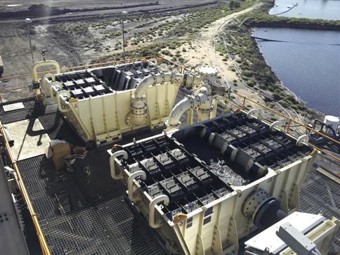
Ghosh et al. (2012) report on an installation of two Reflux Classifiers treating 1–0.5 mm coal at 110 t h−1 with excellent ash reduction. Pilot tests have shown potential for use in processing fine iron ore (Amariei et al., 2014). Figure 10.33 shows a recent installation on a coal processing plant in Australia.
10.7 Dry Processing
Honaker et al. (2014) review the historical development of using air as the medium to achieve gravity-based separations. The initial prime application was in coal preparation, peaking in tons treated in the United States around the mid-1960s. The pneumatic technologies follow the same basic mechanisms described for wet processing. With demand to reduce water usage growing, these technologies are worth reexamining.
Pneumatic Tables
These were initially the most common pneumatic gravity devices. They use the same throwing motion as their wet counterparts to move the feed along a flat riffled deck, while blowing air continuously up through a porous bed. The stratification produced is somewhat different from that of wet tables. Whereas in wet tabling the particle size increases and the density decreases from the top of the concentrate band to the tailings, on an air table both particle size and density decrease from the top down, the coarsest particles in the middlings band having the lowest density. Pneumatic tabling is therefore similar in effect to hydraulic classification. They are commonly used in combination with wet tables to clean zircon concentrates, one of the products obtained from heavy mineral sand deposits. Such concentrates are often contaminated with small amounts of fine quartz, which can effectively be separated from the coarse zircon particles by air tabling. Some fine zircon may be lost in the tailings and can be recovered by treatment on wet shaking tables. Recent testwork into air tabling for coal is detailed by Honaker et al. (2008) and Gupta et al. (2012). A modified air-table, the FGX Dry Separator, from China is modeled by Akbari et al. (2012).
Air Jigs
Gaudin (1939) describes devices common in the early part of the last century. Two modern descendants are the Stump jig and the Allair jig (Honaker et al., 2014). These units employ a constant air flow through a jig bed supported on a fixed screen in order to open the bed and allow stratification. Bed level is sensed and used to control the discharge rate in proportion to the amount of material to be rejected. There are several installations around the world, mostly for coal cleaning. Commercial units, for example, can treat up to 60 t h−1 of 75–12 mm coal (Honaker et al., 2014).
Other Pneumatic-Based Devices
Various units have been modified to operate dry including: the Reflux Classifier (Macpherson and Galvin, 2010), Knelson concentrator (Greenwood et al., 2013; Kökkılıç et al., 2015), Reichert cone (Rotich et al., 2013), and fluidized bed devices (Franks et al., 2013). The latter devices overlap with DMS. For example, applications in coal employ a dense medium of air and magnetite, the air dense medium fluidized bed (ADMFB) process. The first commercial ADMFB installation was a 50 t h−1 unit in China in 1994 (Honaker et al., 2014). Various ADMFB processes are reviewed by Sahu et al. (2009).
10.8 Single-Stage Units and Circuits
Single Versus Two Stages of Spirals
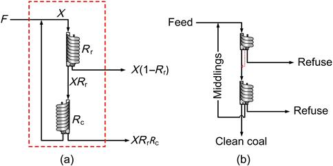
As noted, one of the innovations in coal processing is to incorporate circuits. By making some simplifying assumptions, it is possible to deduce an analytical solution for a circuit, as Luttrell (2002) demonstrates based on the work of Meloy (1983). (The same approach is used quite extensively in Chapter 12, Section 12.11.) Figure 10.34(a) shows two stages of spiral in a possible coal application: the rougher gives a final discard heavy product (refuse) and light product that is sent to a cleaner stage which gives the final light product (i.e., clean coal) with the heavy product (middlings) being recycled to the rougher. For this rougher-cleaner circuit the solution for the circuit recovery Rcirc is given by a mass balance across the dashed box.
Letting the feed to the rougher be X (mass units per unit time) then:
(10.5)
and thus circuit recovery is:
(10.6)
For each unit there is a partition curve, that is, recovery to specified concentrate as a function of particle density. Figure 10.35 shows a generic partition curve in reduced form (Chapter 1), where the abscissae is density divided by the density corresponding to 50% recovery, that is, ρ/ρ50. (Note the values of ρ/ρ50 decrease from left to right, indicating the concentrate is the light product, e.g., clean coal.) The slope at any point is the sharpness of the separation (the ability to separate between density classes). Assuming the same recovery point for both units, we can differentiate to solve for the sharpness of separation (slope) of the circuit, namely:
(10.7)
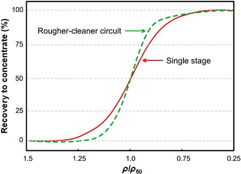
A convenient point for comparison is the slope at ρ/ρ50=1, or R=0.5, which upon substituting in Eq. (10.7) gives dRcirc/dR=1.33; in other words, the slope at ρ/ρ50=1 for the circuit is 1.33 times that for the single unit. This increase in sharpness is illustrated in Figure 10.35 (dashed line). A variety of circuits can be analyzed using this approach (Noble and Luttrell, 2014).
The circuit, in effect, compensates for deficiencies in the stage separation. When the stage separation efficiency is high, such as in DMS (Chapter 11), circuits offer less benefit. But this is rather the exception and is why circuits are widely used in mineral processing, for example, rougher-cleaner-recleaner spiral circuits in iron ore processing, and the wide range of flotation circuits is evident in Chapter 12. Circuits are less common in coal processing, but the advantage can be demonstrated (Bethell and Arnold, 2002).
Rather than two stages of spirals, Figure 10.34(b) shows a two-stage compound spiral. Typically, spiral splitters will give three products, for example, in the case of a coal application: clean coal, refuse, and middlings. In the compound spiral the top three-turn spiral (in this example) produces final refuse, and the clean coal and middlings are combined and sent to the lower four-turn spiral, which produces another final refuse, final clean coal, and a middlings, which is recycled. Bethell and Arnold (2002) report that compared to two stages of spirals, the compound spiral had reduced floor space requirements with reduced capital and operating costs and was selected for a plant expansion.
Parallel Circuits
Coal preparation plants usually have parallel circuits producing a final product as a blend. Luttrell (2014) describes a generic flowsheet comprising four independent circuits, each designed to treat a particular particle size: coarse (>10 mm) using dense medium baths, medium (10–1 mm) using dense medium cyclones, small (1–0.15 mm) using spirals, and fine (<0.15 mm) by flotation. This arrangement poses the interesting question: what is the optimum blend of the four products to meet the target coal quality (ash grade) specification? It might seem that controlling all four to produce the same ash content would be the answer. However as Luttrell (2002) shows, the answer is to blend when each circuit has achieved the same target incremental ash grade. (The increment in grade can be understood using the grade-gradient plot in Appendix III; the tangent to the operating line is the incremental grade.) In this manner the yield of coal product will be maximized at the target ash grade for the blend; that is, in this respect the process is optimized. Since coal feeds are basically a two-density mineral situation (coal and ash minerals), then the density of composite (locked) coal-ash mineral particles will exactly reflect the composition, that is, the ash grade. This means that the density cutpoint for each circuit should be the same so that the increment of product from each at the cutpoint density has the same increment in density and thus the same increment in ash grade. These considerations are of less import in most ore processing plants, which usually comprise one flowsheet producing final concentrate, but whenever more than one independent product is being combined to produce final concentrate this same question of the optimized blend arises.