
Main Modules in a Gas Turbine (Air, Land, or Sea Applications)
Compressors2
In the gas turbine engine, compression of the air before expansion through the turbine is effected by one of two basic types of compressor, one giving centrifugal flow and the other axial flow. Both types are driven by the engine turbine and are usually coupled direct to the turbine shaft.
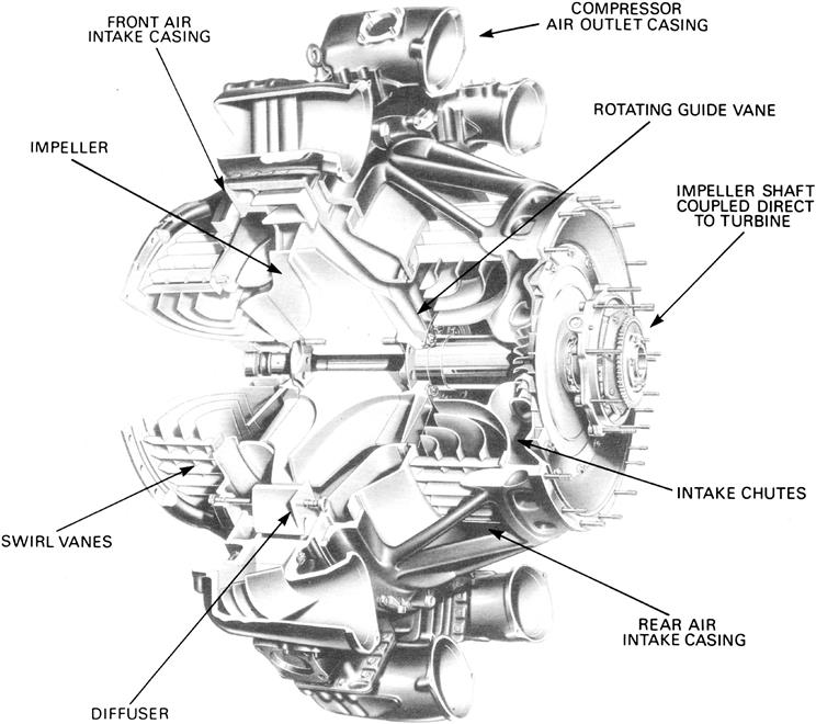
The centrifugal flow compressor (Figure 4–20) is a single- or two-stage unit employing an impeller to accelerate the air and a diffuser to produce the required pressure rise. The axial flow compressor (shown later in Figures 4–26 and 4–27) is a multi-stage unit employing alternate rows of rotating (rotor) blades and stationary (stator) vanes, to accelerate and diffuse the air until the required pressure rise is obtained. In some cases, particularly on small engines, an axial compressor is used to boost the inlet pressure to the centrifugal compressor.
With regard to the advantages and disadvantages of the two types, the centrifugal compressor is usually more robust than the axial compressor and is also easier to develop and manufacture. The axial compressor, however, consumes far more air than a centrifugal compressor of the same frontal area and can be designed to attain much higher pressure ratios. Since the airflow is an important factor in determining the amount of thrust, this means the axial compressor engine will also give more thrust for the same frontal area. This, plus the ability to increase the pressure ratio by addition of Odra stages, has led to the adoption of axial compressors in most engine designs. However, the centrifugal compressor is still favored for smaller engines, where its simplicity and ruggedness outweigh any other disadvantages.
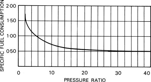
The trend to high-pressure ratios that has favored the adoption of axial compressors is because of the improved efficiency that results, which in turn leads to improved specific fuel consumption for a given thrust, Figure 4–24.
Centrifugal Flow Compressor
Centrifugal flow compressors have a single- or double-sided impeller and occasionally a two-stage, single-sided impeller is used, as on the Rolls Royce Dart. The impeller is supported in a casing that also contains a ring of diffuser vanes. If a double-entry impeller is used, the airflow to the rear side is reversed in direction and a plenum chamber is required.
Principles of Operation
The impeller is rotated at high speed by the turbine and air is continuously induced into the center of the impeller. Centrifugal action causes it to flow radially outwards along the vanes to the impeller tip, thus accelerating the air and also causing a rise in pressure to occur. The engine intake duct may contain vanes that provide an initial swirl to the air entering the compressor.
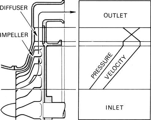
The air, on leaving the impeller, passes into the diffuser section where the passages form divergent nozzles that convert most of the kinetic energy into pressure energy, as
illustrated in Figure 4–25. In practice, it is usual to design the compressor so that about half of the pressure rise occurs in the impeller and half in the diffuser.
To maximize the airflow and pressure rise through the compressor requires the impeller to be rotated at high
speed, therefore impellers are designed to operate at tip speeds of up to 1600 ft per sec. By operating at such high tip speeds, the air velocity from the impeller is increased so that greater energy is available for conversion to pressure.
To maintain the efficiency of the compressor, it is necessary to prevent excessive air leakage between the impeller and the casing: this is achieved by keeping their clearances as small as possible (Figure 4–26).
Construction
The construction of the compressor centers around the impeller, diffuser, and air intake system. The impeller shaft rotates in ball and roller bearings and is either common to the turbine shaft or split in the center and connected by a coupling, which is usually designed for ease of detachment.
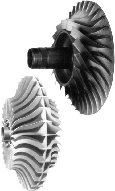
Impellers
The impeller consists of a forged disc with integral, radially disposed vanes on one or both sides (Figure 4–27) forming convergent passages in conjunction with the compressor casing. The vanes may be swept back, but for ease of manufacture, straight radial vanes are usually employed. To ease the air from axial flow in the entry duct on to the rotating impeller, the vanes in the center of the impeller are curved in the direction of rotation. The curved sections may be integral with the radial vanes or formed separately for easier and more accurate manufacture.
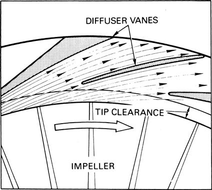
Diffusers
The diffuser assembly may be an integral part of the compressor casing or a separately attached assembly. In each instance it consists of a number of vanes formed tangential to the impeller. The vane passages are divergent to convert the kinetic energy into pressure energy and the inner edges of the vanes are in line with the direction of the resultant airflow from the impeller (Figure 4–28a-c). The clearance between the impeller and the diffuser is an important factor, as too small a clearance will set up aerodynamic buffeting impulses that could be transferred to the impeller and create an unsteady airflow and vibration.
Axial Flow Compressor
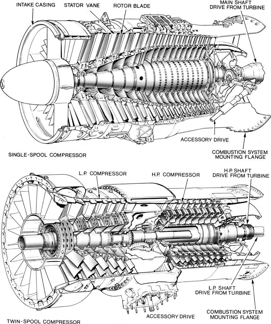
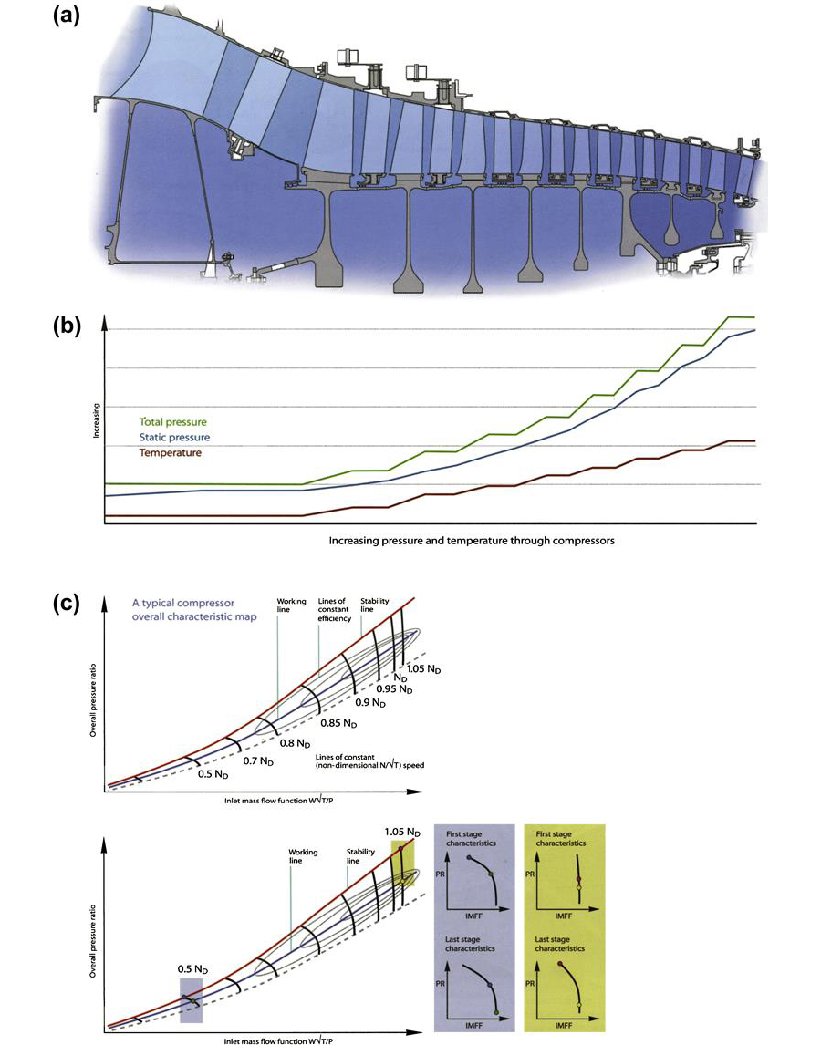
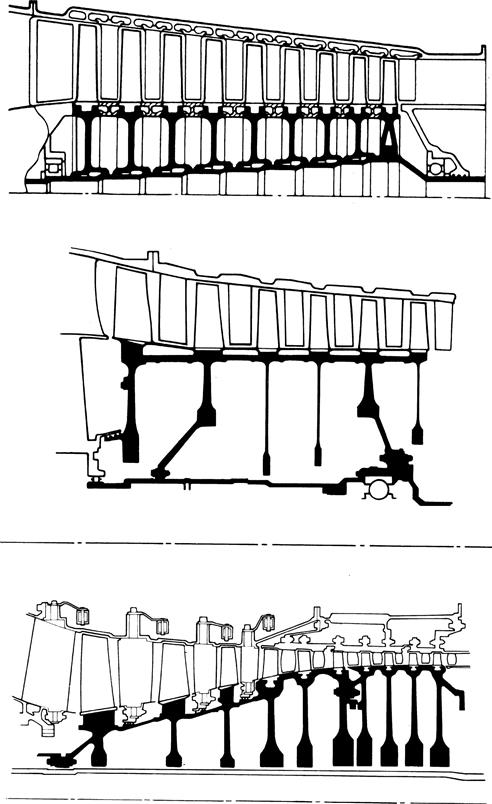
An axial flow compressor (Figures 4–26 and 4–27) consists of one or more rotor assemblies that carry blades of airfoil section. These assemblies are mounted between bearings in the casings that incorporate the stator vanes. The compressor is a multi-stage unit as the amount of pressure increase by each stage is small; a stage consists of a row of rotating blades followed by a row of stator vanes. Where several stages of compression operate in series on one shaft, it becomes necessary to vary the stator vane angle to enable the compressor to operate effectively at speeds below the design condition. As the pressure ratio is increased the incorporation of variable stator vanes ensures that the airflow is directed onto the succeeding stage of rotor blades at an acceptable angle; see the section “Airflow Control.”
From the front to the rear of the compressor, i.e., from the low- to the high-pressure end, there is a gradual reduction of the air annulus area between the rotor shaft and the stator casing. This is necessary to maintain a near constant air axial velocity as the density increases through the length of the compressor. The convergence of the air annulus is achieved by the tapering of the casing or rotor. A combination of both is also possible, with the arrangement being influenced by manufacturing problems and other mechanical design factors.
A single-spool compressor (Figure 4–26) consists of one rotor assembly and stators with as many stages as necessary to achieve the desired pressure ratio, and all the airflow from the intake passes through the compressor.
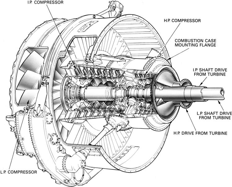
The multispool compressor consists of two or more rotor assemblies, each driven by their own turbine at an optimum speed to achieve higher pressure ratios and to give greater operating flexibility.
Although a twin-spool compressor (Figure 4–26) can be used for a pure jet engine, it is most suitable for the bypass type of engine, where the front or low-pressure compressor is designed to handle a larger airflow than the high-pressure compressor. Only a percentage of the air from the low-pressure compressor passes into the high-pressure compressor; the remainder of the air, the bypass flow, is ducted around the high-pressure compressor. Both flows mix in the exhaust system before passing to the propelling nozzle. This arrangement matches the velocity of the jet nearer to the optimum requirements of the aircraft and results in higher propulsive efficiency, hence lower fuel consumption. For this reason the pure jet engine where all the airflow passes through the full compression cycle is now obsolete for all but the highest speed aircraft.
With the high bypass ratio turbofan this trend is taken a stage further. The intake air undergoes only one stage of compression in the fan before being split between the core or gas generator system and the bypass duct in the ratio of approximately 1 to 5 (Figure 4–27). This results in the optimum arrangement for passenger and/or transport aircraft flying at just below the speed of sound. The fan may be coupled to the front of a number of core compression stages (two shaft engine) or a separate shaft driven by its own turbine (three shaft engine).
Principles of Operation
During operation the rotor is turned at high speed by the turbine so that air is continuously induced into the compressor, which is then accelerated by the rotating blades and swept rearwards onto the adjacent row of stator vanes. The pressure rise results from the energy imparted to the air in the rotor, which increases the air velocity. The air is then decelerated (diffused) in the following stator passage and the kinetic energy translated into pressure. Stator vanes also serve to correct the deflection given to the air by the rotor blades and to present the air at the correct angle to the next stage of rotor blades. The last row of stator vanes usually act as air straighteners to remove swirl from the air prior to entry into the combustion system at a reasonably uniform axial velocity. Changes in pressure and velocity that occur in the airflow through the compressor are shown diagrammatically in Figure 4–28a-c. The changes are accompanied by a progressive increase in air temperature as the pressure increases.
Across each stage the ratio of total pressures of outgoing air and inlet air is quite small, being between 1:1 and 1:2. The reason for the small pressure increase through each stage is that the rate of diffusion and the deflection angle of the blades must be limited if losses due to air breakaway at the blades and subsequent blade stall are to be avoided. Although the pressure ratio of each stage is small, every stage increases the exit pressure of the stage that precedes it. So while this first stage of a compressor may only increase the pressure by 3–4 lb per sq. in., at the rear of a 30:1 compression system the stage pressure rise can be up to 80 lb per sq. in. The ability to design multi-stage axial compressors with controlled air velocities and straight through flow minimizes losses and results in a high efficiency and hence low fuel consumption. This gives it a further advantage over the centrifugal compressor, where these conditions are fundamentally not so easily achieved.
The more the pressure ratio of a compressor is increased the more difficult it becomes to ensure that it will operate efficiently over the full-speed range. This is because the requirement for the ratio of inlet area to exit area, at the high-speed case, results in an inlet area that becomes progressively too large relative to the exit area as the compressor speed and hence pressure ratio is reduced. The axial velocity of the inlet air in the front stages thus becomes low relative to the blade speed, this changes the incidence of the air onto the blades and a condition is reached where the flow separates and the compressor flow breaks down. Where high-pressure ratios are required from a single compressor this problem can be overcome by introducing variable stator vanes in the front stages of the system. This corrects the incidence of air onto the rotor blades to angles that they can tolerate. An alternative is the incorporation of interstage bleeds, where a proportion of air after entering the compressor is removed at an intermediate stage and dumped into the bypass flow. While this method corrects the axial velocity through the preceding stages, energy is wasted and incorporation of variable stators is preferred.
The fan of the high bypass ratio turbofan is an example of an axial compressor that has been optimized to meet the specific requirements of this cycle. While similar in principle to the core compressor stage, the proportions of design are such that the inner gas path is similar to that of the core compressor that follows it, while the tip diameter is considerably larger. The mass flow passed by the fan is typically six times that required by the core, the remaining five sixths bypass the core and is expanded through its own coaxial nozzle or may be mixed with the flow at exit from the core in a common nozzle. To optimize the cycle the bypass flow has to be raised to a pressure of approximately 1.6 times the inlet pressure. This is achieved in the fan by utilizing very high tip speeds (1500 ft per sec) and airflow such that the bypass section of the blades operates with a supersonic inlet air velocity of up to Mach 1.5 at the tip. The pressure that results is graded from a high value at the tip, where relative velocities are highest, to the more normal values of 1.3–1.4 at the inner radius, which supercharges the core where aerodynamic design is more akin to that of a conventional compressor stage. The capability of this type of compressor stage achieves the cycle requirement of high flow per unit of frontal area, high efficiency, and high-pressure ratio in a single rotating blade row without inlet guide vanes within an acceptable engine diameter, thus keeping weight and mechanical complexity at an acceptable level.
Construction
The construction of the compressor centers around the rotor assembly and casings. The rotor shaft is supported in ball and roller bearings and coupled to the turbine shaft in a manner that allows for any slight variation of alignment. The cylindrical casing assembly may consist of a number of cylindrical casings with a bolted axial joint between each stage or the casing may be in two halves with a bolted center line joint. One or other of these construction methods is required in order that the casing can be assembled around the rotor.
Rotors
In compressor designs (Figure 4–29) the rotational speed is such that a disc is required to support the centrifugal blade load. Where a number of discs are fitted onto one shaft they may be coupled and secured together by a mechanical fixing but generally the discs are assembled and welded together, close to their periphery, thus forming an integral drum.
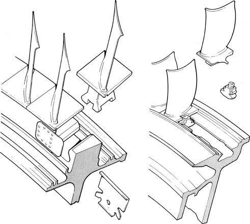
Typical methods of securing rotor blades to the disc are shown in Figure 4–30; fixing may be circumferential or axial to suit special requirements of the stage. In general the aim is to design a securing feature that imparts the lightest possible load on the supporting disc thus minimizing disc weight. While most compressor designs have separate blades for manufacturing and maintainability requirements, it becomes more difficult on the smallest engines to design a practical fixing. However, this may be overcome by producing blades integral with the disc: the so-called blisk.
Rotor Blades
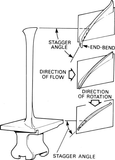
The rotor blades are of airfoil section (Figure 4–31) and usually designed to give a pressure gradient along their length to ensure that the air maintains a reasonably uniform axial velocity. The higher pressure towards the tip balances out the centrifugal action of the rotor on the airstream. To obtain these conditions, it is necessary to “twist” the blade from root to tip to give the correct angle of incidence at each point. Air flowing through a compressor creates two boundary layers of slow to stagnant air on the inner and outer walls. In order to compensate for the slow air in the boundary layer a localized increase in blade camber both at the blade tip and root has been introduced. The blade extremities appear as if formed by bending over each corner, hence the term “end-bend.”
Stator Vanes
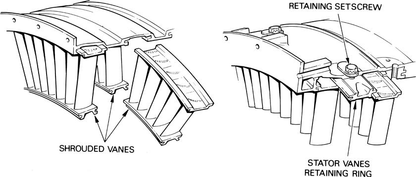
The stator vanes are again of airfoil section and are secured into the compressor casing or into stator vane retaining rings, which are themselves secured to the casing (Figure 4–32). The vanes are often assembled in segments in the front stages and may be shrouded at their inner ends to minimize the vibrational effect of flow variations on the longer vanes. It is also necessary to lock the stator vanes in such a manner that they will not rotate around the casing.
Operating Conditions
Each stage of a multi-stage compressor possesses certain airflow characteristics that are dissimilar from those of its neighbor; thus to design a workable and efficient compressor, the characteristics of each stage must be carefully matched. This is a relatively simple process to implement for one set of conditions (design mass flow, pressure ratio, and rotational speed), but is much more difficult when reasonable matching is to be retained with the compressor operating over a wide range of conditions such as an aircraft engine encounters.
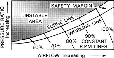
If the operating conditions imposed upon the compressor blade depart too far from the design intention, breakdown of airflow and/or aerodynamically induced vibration will occur. These phenomena may take one of two forms: the blades may stall because the angle of incidence of the air relative to the blade is too high (positive incidence stall) or too low (negative incidence stall). The former is a front stage problem at low speeds and the latter usually affects the rear stages at high speed; either can lead to blade vibration that can induce rapid destruction. If the engine demands a pressure rise from the compressor that is higher than the blading can sustain, “surge” occurs. In this case there is an instantaneous breakdown of flow through the machine and the high-pressure air in the combustion system is expelled forward through the compressor with a loud “bang” and a resultant loss of engine thrust. Compressors are designed with adequate margin to ensure that this area of instability (Figure 4–33) is avoided.
Airflow Control
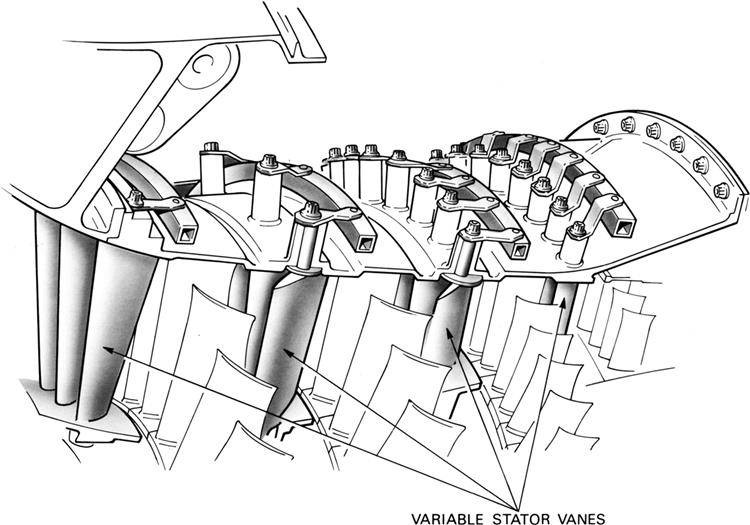
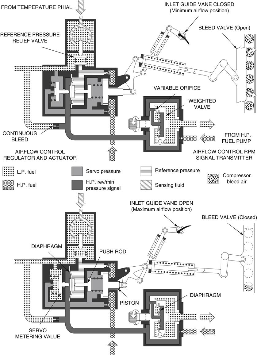
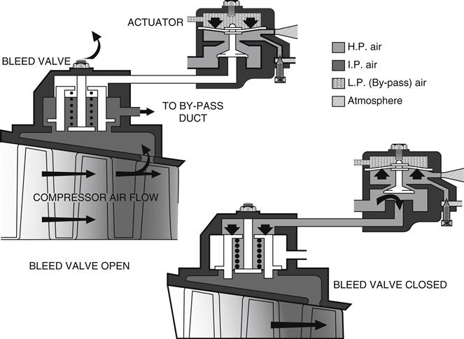
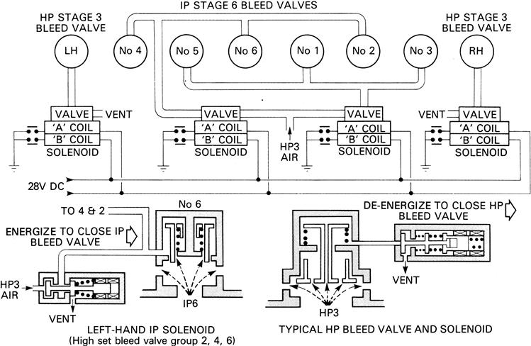
Where high-pressure ratios on a single shaft are required it becomes necessary to introduce airflow control into the compressor design. This may take the form of variable inlet guide vanes for the first stage plus a number of stages incorporating variable stator vanes for the succeeding stages as the shaft pressure ratio is increased (Figure 4–34). As the compressor speed is reduced from its design value these static vanes are progressively closed in order to maintain an acceptable air angle value onto the following rotor blades. Additionally interstage bleed may be provided but its use in design is now usually limited to the provision of extra margin while the engine is being accelerated, because use at steady operating conditions is inefficient and wasteful of fuel. Three types of air bleed systems are illustrated as follows: Figure 4–35, hydraulic; Figure 4–36, pneumatic; and Figure 4–37, electronic.
Materials
Materials are chosen to achieve the most cost-effective design for the components in question, in practice for aeroengine design this need is usually best satisfied by the lightest design that technology allows for the given loads and temperatures prevailing.
For casing designs the need is for a light but rigid construction enabling blade tip clearances to be accurately maintained, ensuring the highest possible efficiency. These needs are achieved by using aluminum at the front of the compression system followed by alloy steel as compression temperature increases, while for the final stages of the compression system, where temperature requirements possibly exceed the capability of the best steel, nickel-based alloys may be required. The use of titanium in preference to aluminum and steel is now more common; particularly in military engines where its high rigidity to density ratio can result in significant weight reduction. With the development of new manufacturing methods, component costs can now be maintained at a more acceptable level in spite of high initial material costs.
Stator vanes are normally produced from steel or nickel-based alloys, a prime requirement being high fatigue strength when “notched” by ingestion damage. Earlier designs specified aluminum alloys but because of its inferior ability to withstand damage its use has declined. Titanium may be used for stator vanes in the low-pressure area but is unsuitable for the smaller stator vanes further rearwards in the compression system because of the higher pressures and temperatures encountered. Any excessive rub that may occur between rotating and static components as a result of other mechanical failures can generate sufficient heat from friction to ignite the titanium. This in turn can lead to expensive repair costs and a possible airworthiness hazard.
In the design of rotor discs, drums, and blades, centrifugal forces dominate and the requirement is for metal with the highest ratio of strength to density. This results in the lightest possible rotor assembly, which in turn reduces the forces on the engine structure enabling a further reduction in weight to be obtained. For this reason, titanium even with its high initial cost is the preferred material and has replaced the steel alloys that were favored in earlier designs. As higher temperature titanium alloys are developed and produced, they are progressively displacing the nickel alloys for the disc and blades at the rear of the system.
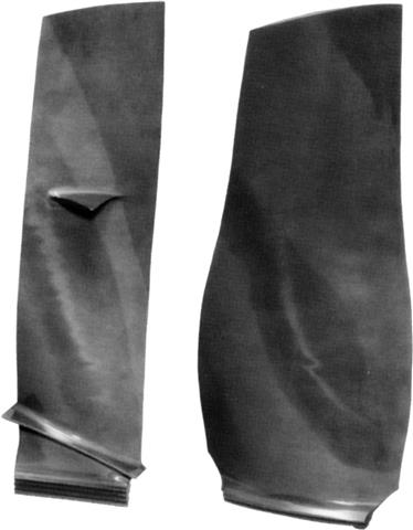
The high bypass ratio fan blade (Figure 4–38) only became a design possibility with the availability of titanium, conventional designs being machined from solid forgings. A low weight fan blade is necessary because the front structure of the engine must be able to withstand the large out of balance forces that would result from a fan blade failure. To achieve a sufficiently light solid fan blade, even with titanium, requires a short axial length (or chord). However, with this design, the special feature of a mid-span support (“snubber” or “clapper”) is required to prevent aerodynamic instability. This design concept has the disadvantage of the snubber being situated in the supersonic flow where pressure losses are greatest, resulting in inefficiency and a reduction in airflow. This disadvantage has been overcome with the introduction of the Rolls Royce designed wide chord fan blade; stability is provided by the increased chord of the blade thus avoiding the need for snubbers. The weight is maintained at a low level by fabricating the blade from skins of titanium incorporating a honeycomb core.
Centrifugal impeller material requirements are similar to those for the axial compressor rotors. Titanium is thus normally specified though aluminum may still be employed on the largest low-pressure ratio designs where robust sections give adequate ingestion capability and temperatures are acceptably low.
Balancing
The balancing of a compressor rotor or impeller is an extremely important operation in its manufacture. In view of the high rotational speeds and the mass of materials, any unbalance would affect the rotating assembly bearings and engine operation. Balancing on these parts is effected on a special balancing machine.
Combustors3
Combustion Chambers
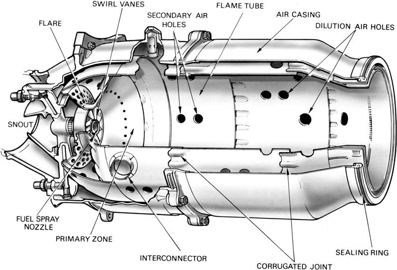
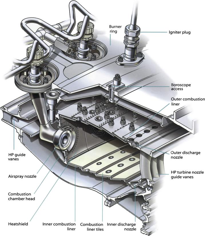
The combustion chamber (Figure 4–39) has the difficult task of burning large quantities of fuel, supplied through the fuel spray nozzles, with extensive volumes of air, supplied by the compressor and releasing the heat in such a manner that the air is expanded and accelerated to give a smooth stream of uniformly heated gas at all conditions required by the turbine. This task must be accomplished with the minimum loss in pressure and with the maximum heat release for the limited space available.
The amount of fuel added to the air will depend upon the temperature rise required. However, the maximum temperature is limited to within the range of 850–1700°C by the materials from which the turbine blades and nozzles are made. The air has already been heated to between 200 and 550°C by the work done during compression, giving a temperature rise requirement of 650–1150°C from the combustion process. Since the gas temperature required at the turbine varies with engine thrust, and in the case of the turbopropeller engine upon the power required, the combustion chamber must also be capable of maintaining stable and efficient combustion over a wide range of engine operating conditions.
Efficient combustion has become increasingly important because of the rapid rise in commercial aircraft traffic and the consequent increase in atmospheric pollution, which is seen by the general public as exhaust smoke.
Combustion Process
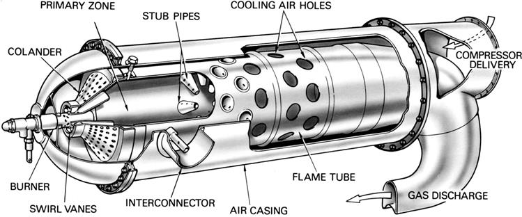
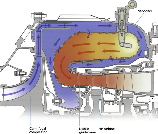
Air from the engine compressor enters the combustion chamber at a velocity up to 500 ft per sec, but because at this velocity the air speed is far too high for combustion, the first thing that the chamber must do is to diffuse it, i.e., decelerate it and raise its static pressure. Since the speed of burning kerosene at normal mixture ratios is only a few feet per second, any fuel lit even in the diffused air stream, which now has a velocity of about 80 ft per sec, would be blown away. A region of low axial velocity has therefore to be created in the chamber, so that the flame will remain alight throughout the range of engine operating conditions.
In normal operation, the overall air/fuel ratio of a combustion chamber can vary between 45:1 and 130:1. However, kerosene will only burn efficiently at, or close to, a ratio of 15:1, so the fuel must be burned with only part of the air entering the chamber, in what is called a primary combustion zone. This is achieved by means of a flame tube (combustion liner) that has various devices for metering the airflow distribution along the chamber.
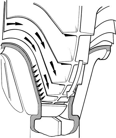
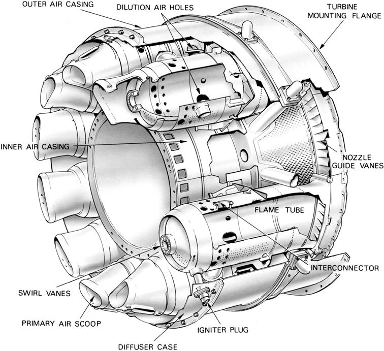
Approximately 20% of the air mass flow is taken in by the snout or entry section (Figure 4–40). Immediately downstream of the snout are swirl vanes and a perforated flare, through which air passes into the primary combustion zone. The swirling air induces a flow upstream of the center of the flame tube and promotes the desired recirculation. The air not picked up by the snout flows into the annular space between the flame tube and the air casing.
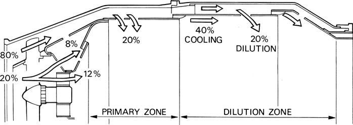
Through the wall of the flame tube body, adjacent to the combustion zone, are a selected number of secondary holes through which a further 20% of the main flow of air passes into the primary zone. The air from the swirl vanes and that from the secondary air holes interact and create a region of low velocity recirculation. This takes the form of a toroidal vortex, similar to a smoke ring, which has the effect of stabilizing and anchoring the flame (Figure 4–41). The recirculating gases hasten the burning of freshly injected fuel droplets by rapidly bringing them to ignition temperature.
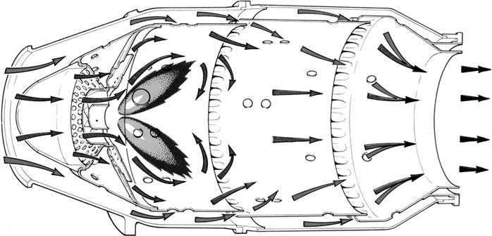
It is arranged that the conical fuel spray from the nozzle intersects the recirculation vortex at its center. This action, together with the general turbulence in the primary zone, greatly assists in breaking up the fuel and mixing it with the incoming air.
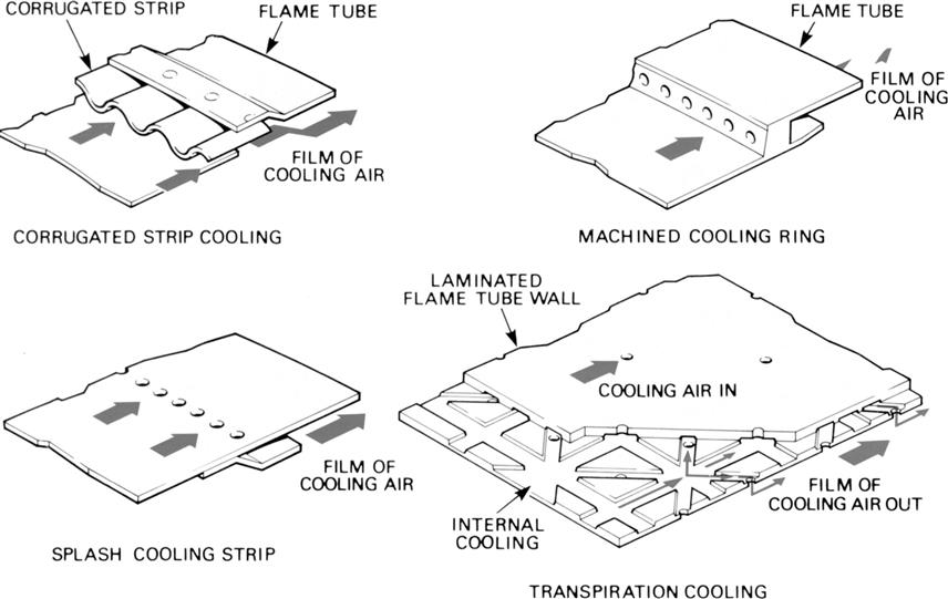
The temperature of the gases released by combustion is about 1800–2000°C, which is far too hot for entry to the nozzle guide vanes of the turbine. The air not used for combustion, which amounts to about 60% of the total airflow, is therefore introduced progressively into the flame tube. Approximately a third of this is used to lower the gas temperature in the dilution zone before it enters the turbine and the remainder is used for cooling the walls of the flame tube. This is achieved by a film of cooling air flowing along the inside surface of the flame tube wall, insulating it from the hot combustion gases (Figure 4–42). A recent development allows cooling air to enter a network of passages within the flame tube wall before exiting to form an insulating film of air; this can reduce the required wall cooling airflow by up to 50%. Combustion should be completed before the dilution air enters the flame tube, otherwise the incoming air will cool the flame and incomplete combustion will result.
An electric spark from an igniter plug initiates combustion and the flame is then self-sustained.
The design of a combustion chamber and the method of adding the fuel may vary considerably, but the airflow distribution used to effect and maintain combustion is always very similar to that described.
Fuel Injectors
The fuel has to be delivered to the combustion chamber where it is thoroughly mixed with air before combustion. For liquid fuels, there are two distinct methods of doing this: vaporizers and fuel spray nozzles, the latter comprising the two main types of pressure-jets and airspray injectors.
Vaporizers
Vaporizers are comparatively simple, cheap, and lightweight structures that serve to mix the fuel and air. Fuel is injected through a fuel-feed tube or sprayer into an L- or T-shaped tube that turns the fuel/air mixture through 180 degrees. The corners of the vaporizer are typically sharp and are intended to create vortices and promote mixing. These may be supplemented by weirs inside the vaporizer, which also encourage turbulence and mixing. Although the fuel/air mixture is heated inside the vaporizer, most of the mixture leaves the vaporizer and impinges on the combustor baseplate as a series of droplets that receive heat and are vaporized by the high temperatures in the primary zone of the combustor. Some combustor designs require the addition of specialized air feed features such as “blown rings” to blow fuel away from the walls to improve efficiency. Engines with vaporizers additionally require primers, which are pressure-jet fuel injectors, to improve ignition characteristics by delivering atomized fuel near the igniters.
The vaporizer is fuel-cooled and has a tendency to overheat when the engine decelerates because the combustion gases in the primary zone are still radiating and conducting heat, but there is little fuel to cool the vaporizer. Because it is fuel-cooled, the vaporizer is also susceptible to overheating caused by blockage of the fuel feed tube.
Vaporizers have been predominant in applications requiring simple, cheap, and lightweight fuel injectors, particularly military aero engines like the Pegasus and RB199, and the RTM322 and Gem helicopter engines. They were also used in the Olympus 593 that powered Concorde. They have not been favored on large civil aero engines because of durability and emissions requirements.
While vaporizers are able to offer high efficiencies and can give low smoke at reasonably high pressures, they are unable to produce satisfactorily low smoke at the very high temperatures and pressures seen in the latest generation of civil and military high-thrust aero engines.
Fuel Spray Nozzles
The fuel spray nozzles atomize the fuel to ensure its rapid evaporation and burning when mixed with air. This combustion is a difficult process for two reasons: the velocity of the air stream from the compressor creates a hostile environment for the flame, while the short length of the combustion system means there is little time for burning to occur.
Pressure-Jet Injectors
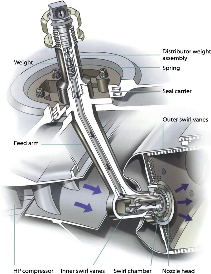
One technique of atomizing the fuel is to pass it through a swirl chamber where tangential holes or slots impart swirl to the fuel. The fuel is then passed through the discharge orifice, where the fuel is atomized to form a cone-shaped spray. This is called pressure-jet atomization. The rate of swirl and pressure of the fuel at the fuel spray nozzle are important factors in good atomization. The shape of the spray is an indication of the degree of atomization: at low fuel pressures, a continuous film of fuel is formed, known as a “bubble”; at intermediate fuel pressures, the film breaks up at the edges to form a “tulip”; at high fuel pressures, the tulip shortens towards the orifice and forms a finely atomized spray.
The simplex spray nozzle is a pressure-jet atomizer with a single fuel manifold. Used on early jet engines, it consists of a chamber that induces a swirl into the fuel and a fixed-area atomizing orifice. This nozzle gave good atomization at the higher fuel flows (at high fuel pressures) but was very unsatisfactory at the low pressures required at low engine speeds and especially at high altitude. The simplex is, by the nature of its design, a “square law” spray nozzle; that is, the flow through the nozzle is proportional to the square of the pressure drop across it. This meant that if the
minimum pressure for effective atomization were 200 kPa, the pressure needed to give maximum flow would be about 40,000 kPa. The fuel pumps available at that time were unable to cope with such high pressures.
The duplex and duple fuel spray nozzles require a primary and a main fuel manifold and have two independent orifices, one much smaller than the other. The smaller orifice handles the lower flows; the larger deals with the higher flows as the pressure increases.
A pressurizing valve may be employed with this type of spray nozzle to apportion fuel to the two manifolds. As the fuel flow and pressure increase, the pressurizing valve moves to admit fuel progressively into the main manifold and the main orifices. This combined flow down both manifolds allows the duplex and duple fuel spray nozzles to give effective atomization over a wider flow range than the simplex spray nozzle for the same fuel pressure. The duple has two fuel chambers and two orifices, whereas the duplex has one fuel chamber and two orifices.
Airspray Nozzles
The airspray nozzle uses compressor discharge air to create a finely atomized fuel spray. By aerating the spray, the local fuel-rich concentrations produced by other types of spray nozzle are avoided, giving a reduction in both carbon deposition and exhaust smoke, The airspray fuel spray nozzle will typically have two or three air swirler circuits: an inner, an outer, and a dome. An annular fuel passage between the inner and outer air circuits feeds air onto a prefilming lip. This forms a sheet of fuel that breaks down into ligaments. These ligaments are then broken up into
droplets within the shear layers of the surrounding highly swirling air.
The fuel spray nozzle designer not only has to consider optimizing the atomization of fuel, but also where the fuel droplets are directed. These characteristics can be fine-tuned by altering the quantities of air that pass through each air circuit and the amount of swirl that is imparted. An additional advantage is that the low fuel pressure required for atomization permits the use of the comparatively light gear-type pump.
Fuel Distribution
For larger diameter combustion chambers, a flow distributor valve is often required to compensate for the gravity head across the manifold at low fuel pressures to make sure that all the spray nozzles pass an equal quantity of fuel especially at ignition conditions.
This ensures that all sectors of the combustor operate in the same way, giving repeatability in the temperature distribution seen by the high-pressure (HP) turbine. Small diameter combustion chambers, such as those used on military engines, do not have flow distributor valves, but may nevertheless have to cope with an irregular distribution of fuel pressure caused by high-g maneuvers.
Industrial and Marine Fuel Injectors
Industrial engines have an additional complication in that they may be required to run on both liquid and gaseous fuels. This is approached in different ways, depending upon how quickly the change-over is required: “dual fuel” combustion systems have a single set of fuel injectors and can switch between fuels while running; “double fuel” combustion systems require the swapping of fuel injectors when fuels are changed. Dual fuel nozzles are evolved from aero liquid-fuel spray nozzles; gas-only fuel injectors operate at lower pressures, and some may use a series of plane orifices to impart swirl to the fuel flow.
Igniters
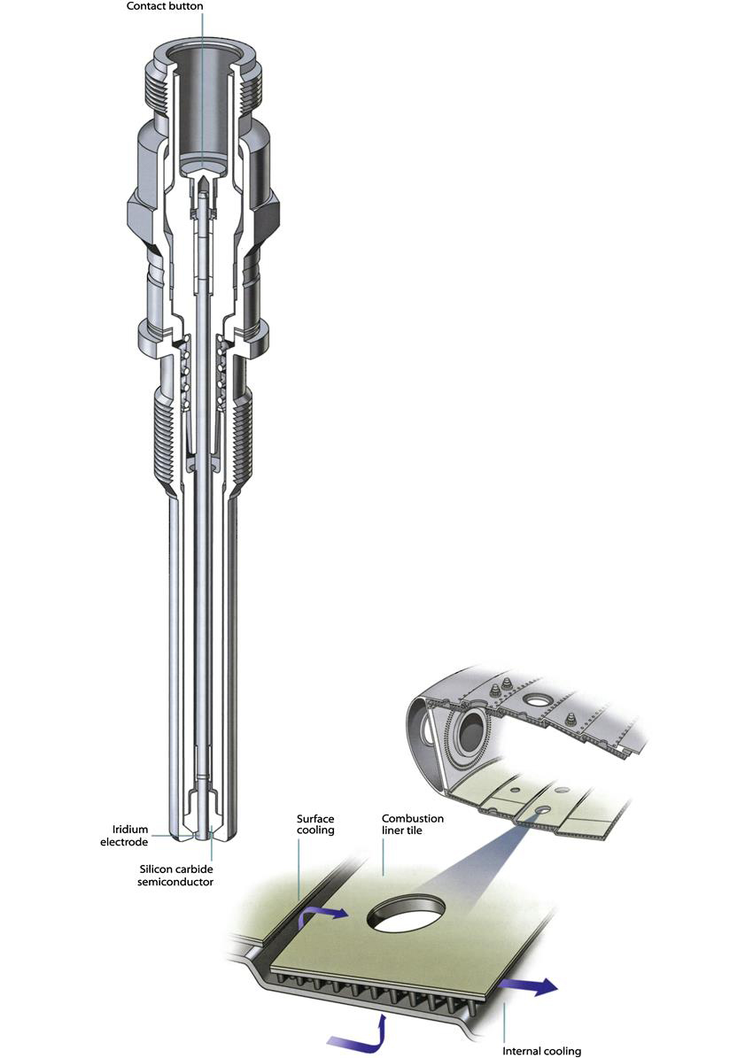
There are two basic types of igniter plug; the constricted or constrained air gap type and the shunted surface discharge type. The air gap type is similar in operation to the conventional reciprocating engine spark plug, but has a larger air gap between the electrode and igniter body for the spark to cross. A potential difference of approximately 25,000 volts is required to ionize the gap before a spark will occur. This high voltage requires very good insulation throughout the circuit. The surface discharge igniter plug has the end of the insulator formed by a semi-conducting pellet, which permits an electrical leakage from the central high-tension electrode to the body. This ionizes the surface of the pellet to provide a low resistance path for the energy stored in the capacitor. The discharge takes the form of a high intensity flashover from the electrode to the body and only requires a potential difference of approximately 2000 volts for operation.
The normal spark rate of a typical ignition system is between 60 and 100 sparks per minute. Periodic replacement of the igniter plug is necessary due to the progressive erosion of the igniter electrodes caused by each discharge.
The igniter tip has a range of immersions into the combustor flame tube of plus or minus one millimeter depending on flame tube design and wall cooling technology. During operation, the spark penetrates a further 20 mm. The fuel mixture is ignited in the relatively stable boundary layer; the flame then propagates throughout the combustion
system. A modern annular combustion system usually has two igniters on opposite sides of the annulus.
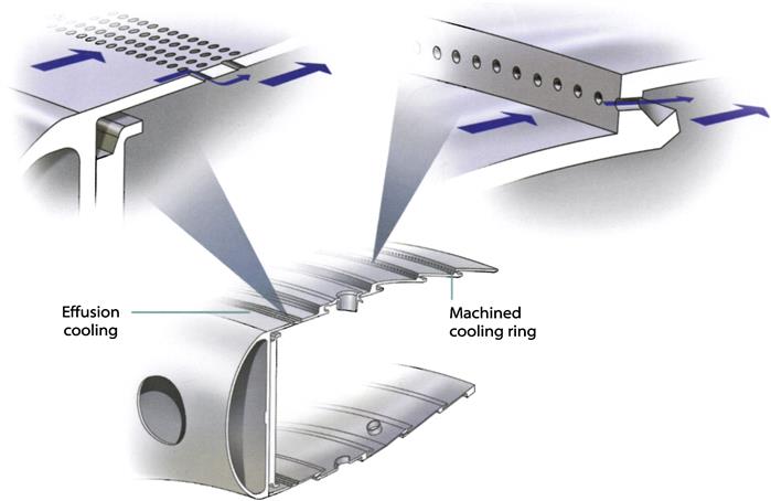
Cooling
The temperature of the gases released by the combustion process may peak above 2100°C and average 1500°C; this is much higher than the melting point of the combustion chamber and turbine materials. The designer must ensure all of the metal surfaces that are exposed to the hot gas are adequately cooled—quite a challenge when the “cold” air used for cooling may itself be at a temperature approaching 700°C. Furthermore, the amount of air used for cooling must be minimized in order to maximize the air available for emissions control.
A commonly employed technique for cooling the combustor wall is to introduce a cooling film at several locations along the wall. The way this film is introduced varies with the manufacturing method of the combustor wall. For example, a combustor manufactured from sheet metal may use a splash cooling strip or a machined cooling ring, whereas a forged or cast wall could accommodate a Z-ring. This may be supplemented by the use of local effusion cooling (holes) and a ceramic thermal barrier coating on the combustor wall.
Many combustors employ ceramic-coated tiles to line the combustor wall. The individual tiles are attached to a cold “skin,” and cooling air passes through holes in the combustor wall and impinges on the tile. The air then moves through a series of pedestals designed to improve the convective heat transfer coefficient, before exiting the front and rear of the tile to form an insulating film. The tiles are designed to be removable for maintenance.
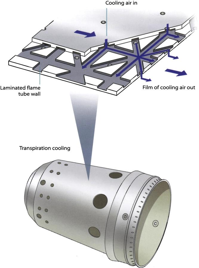
An alternative cooling technique, called transpiration, is to use laminated materials that allow cooling air to enter a network of passages within the flame tube wall before exiting to form an insulating film of air.
The thermal management of fuel-wetted surfaces within the fuel injector is a particular concern. If fuel is exposed to excessive temperatures within the fuel injector, it will decompose to form lacquers and carbon deposits that may block fuel passages or cause distortion. For this reason, the fuel injectors feature complex heat shielding and are carefully designed to prevent regions of stagnant fuel from occurring.
This issue can be more of a problem for industrial and marine applications, where the liquid diesel fuels have lower thermal stability. Subtle combustor cooling changes may also be necessary for industrial and marine applications due to the increased radiation caused by diesel fuel properties.
Predictive Modeling
The modeling of metal temperatures is necessary to determine the displacement, thermal stresses, and life of a component. This modeling is done using finite element analysis. In order to calculate metal temperatures, it is necessary to input material property data, engine performance data, air system data, and heat transfer coefficients. These heat transfer coefficients may be validated by computational fluid dynamics (CFD) analysis and/or rig or engine thermocouple measurements. CFD can also allow the designer to model, first, the flow of air in, through, and out of the combustor, second, the complicated air/fuel mixing, and third, the chemistry behind the combustion process.
Types of Combustion Chamber
There are three main types of combustion chamber in use for gas turbine engines. These are the multiple chamber, the tubo-annular chamber, and the annular chamber.
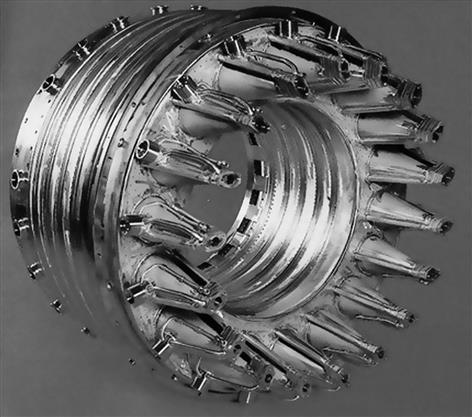
Multiple Combustion Chamber
This type of combustion chamber is used on centrifugal compressor engines and the earlier types of axial flow compressor engines. It is a direct development of the early type of Whittle combustion chamber. The major difference is that the Whittle chamber had a reverse flow as illustrated in Figure 4–47 but, as this created a considerable pressure loss, the straight-through multiple chamber was developed by Joseph Lucas Limited.
The chambers are disposed around the engine (Figure 4–48) and compressor delivery air is directed by ducts to pass into the individual chambers. Each chamber has an inner flame tube around which there is an air casing. The air passes through the flame tube snout and also between the tube and the outer casing as already described.
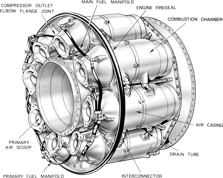
The separate flame tubes are all interconnected. This allows each tube to operate at the same pressure and also allows combustion to propagate around the flame tubes during engine starting.
Tubo-annular Combustion Chamber
The tubo-annular combustion chamber bridges the evolutionary gap between the multiple and annular types. A number of flame tubes are fitted inside a common air casing (Figure 4–49). The airflow is similar to that already described. This arrangement combines the ease of overhaul and testing of the multiple system with the compactness of the annular system.
Annular Combustion Chamber
This type of combustion chamber consists of a single flame tube, completely annular in form, which is contained in an inner and outer casing (Figure 4–50). The airflow through the flame tube is similar to that already described, the chamber being open at the front to the compressor and at the rear to the turbine nozzles.
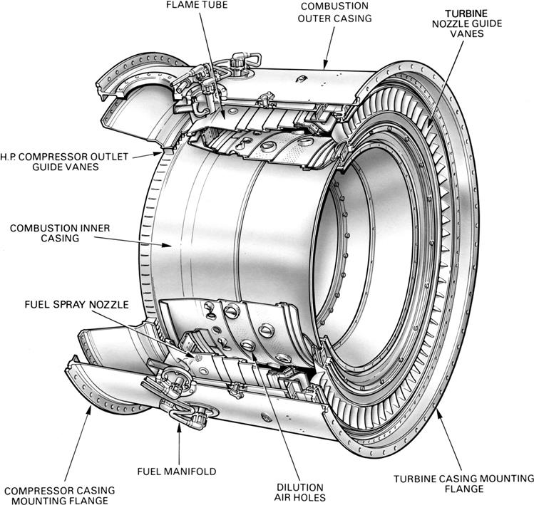
The main advantage of the annular chamber is that, for the same power output, the length of the chamber is only 75% of that of a tubo-annular system of the same diameter, resulting in considerable saving of weight and production cost. Another advantage is the elimination of combustion propagation problems from chamber to chamber.
In comparison with a tubo-annular combustion system, the wall area of a comparable annular chamber is much less; consequently the amount of cooling air required to prevent the burning of the flame tube wall is less, by approximately 15%. This reduction in cooling air raises the combustion efficiency to virtually eliminate unburned fuel and oxidizes the carbon monoxide to nontoxic carbon dioxide, thus reducing air pollution.
The introduction of the air spray type fuel spray nozzle to this type of combustion chamber also greatly improves the preparation of fuel for combustion by aerating the over-rich pockets of fuel vapors close to the spray nozzle; this results in a large reduction in initial carbon formation.
Combustion Chamber Performance
A combustion chamber must be capable of allowing fuel to burn efficiently over a wide range of operating conditions without incurring a large pressure loss. In addition, if flame extinction occurs, then it must be possible to relight. In performing these functions, the flame tube and spray nozzle atomizer components must be mechanically reliable.
The gas turbine engine operates on a constant pressure cycle, therefore any loss of pressure during the process of combustion must be kept to a minimum. In providing adequate turbulence and mixing, a total pressure loss varying from about 3–8% of the air pressure at entry to the chamber is incurred.
Combustion Intensity
The heat released by a combustion chamber or any other heat generating unit is dependent on the volume of the combustion area. Thus, to obtain the required high power output, a comparatively small and compact gas turbine combustion chamber must release heat at exceptionally high rates.
For example, at takeoff conditions a Rolls Royce RB211-524 engine will consume 20,635 lb of fuel per hour. The fuel has a calorific value of approximately 18,550 British thermal units per lb, therefore the combustion chamber releases nearly 106,300 Btus per second. Expressed in another way, this is an expenditure of potential heat at a rate equivalent to approximately 150,000 hp.
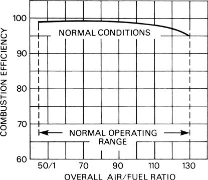
Combustion Efficiency
The combustion efficiency of most gas turbine engines at sea-level takeoff conditions is almost 100%, reducing to 98% at altitude cruise conditions, as shown in Figure 4–53.
Combustion Stability
Combustion stability means smooth burning and the ability of the flame to remain alight over a wide operating range.
For any particular type of combustion chamber there is both a rich and weak limit to the air/fuel ratio, beyond which the flame is extinguished. An extinction is most likely to occur in flight during a glide or dive with the engine idling, when there is a high airflow and only a small fuel flow, i.e., a very weak mixture strength.
The range of air/fuel ratio between the rich and weak limits is reduced with an increase of air velocity, and if the air mass flow is increased beyond a certain value, flame extinction occurs. A typical stability loop is illustrated in Figure 4–54. The operating range defined by the stability loop must obviously cover the air/fuel ratios and mass flow of the combustion chamber.
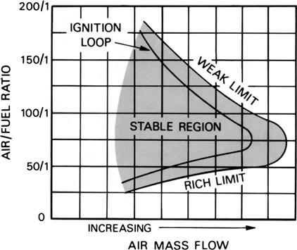
The ignition process has weak and rich limits similar to those shown for stability in Figure 4–54. The ignition loop, however, lies within the stability loop since it is more difficult to establish combustion under “cold” conditions than to maintain normal burning.
Fission
The unwanted pollutants that are found in the exhaust gases are created within the combustion chamber. There are four main pollutants that are legislatively controlled; unburned hydrocarbons (unburned fuel), smoke (carbon particles), carbon monoxide, and oxides of nitrogen. The principal conditions for the formation of pollutants are pressure, temperature, and time.
In the fuel-rich regions of the primary zone, the hydrocarbons are converted into carbon monoxide and smoke. Fresh dilution air can be used to oxidize the carbon monoxide and smoke into nontoxic carbon dioxide within the dilution zone. Unburned hydrocarbons can also be reduced in this zone by continuing the combustion process to ensure complete combustion.
Oxides of nitrogen are formed under the same conditions as those required for the suppression of the other pollutants. Therefore it is desirable to cool the flame as quickly as possible and to reduce the time available for combustion. This conflict of conditions requires a compromise to be made, but continuing improvements in combustor design and performance have led to a substantially “cleaner” combustion process.
Materials
The containing walls and internal parts of the combustion chamber must be capable of resisting the very high gas temperature in the primary zone. In practice, this is achieved by using the best heat-resisting materials available, the use of high heat resistant coatings, and by cooling the inner wall of the flame tube as an insulation from the flame.
The combustion chamber must also withstand corrosion due to the products of the combustion, creep failure due to temperature gradients, and fatigue due to vibrational stresses.
Low NOx Combustors4
From the basic gas turbine cycle discussed in the previous section, one sees that raising the temperature at which the combustion gases enter the turbine (temperature just past the first stage inlet guide vanes or turbine inlet temperature) will also raise the efficiency of the gas turbine cycle. This method of increase in gas turbine efficiency is quite common with certain manufacturers. Care has to be taken, however, that an increase in TITs does not cause other operational problems, such as overheating of turbine components and turbine lubrication oil. If the TIT increase is not accompanied with sufficient additional cooling, this could happen.
Also, one needs to consider that the amount of oxides of nitrogen (NOx) produced by a combustor increases with the value of the flame temperature in the combustor and the corresponding value of TIT. NOx contributes to acid rain and legislation against NOx production has become increasingly stringent. Hence lower TITs, to the extent permitted by optimized efficiency, are desirable. This fact needs to be kept in focus when selecting and/or specifying gas turbines for particular applications and specific demographics (i.e., country or state concerned and their particular legislation).
The NOx products of combustion can be “cleaned up,” or mitigated at any rate, by an external process, such as SCR (selective catalytic reduction), which occurs after combustion.
Low NOx combustors are designed, optimized, and promoted extensively for both performance- and profit-based reasons. The extent of the profit they represent varies with the demographics of the location in question. Specifically,
1. In the United States, as flameless combustor (see later this section) designers are quick to point out, their ultralow single-digit NOx designs succeed in getting their operators legally permitted (to commence power production) in some cases a few months ahead of their rivals, who may have quite respectable NOx levels ranging from 9–15 ppm. This represents a considerable amount of revenue.
2. Both the United States and Canada deal with emissions trading. Regardless of any opinion on the technical wisdom of such measures with respect to the overall atmospheric load, low NOx abilities represent revenue to an operator, who can then sell his or her “spare” credits.
3. In Scandinavian countries, operators pay taxes per unit weight of NOx and SOx emissions. This source of revenue method is spreading through the Western world.
4. Low NOx means that other emissions such as CO and CO2 are also lowered. CO2 taxes may soon be reality in global, particularly Western world, terms. In this aspect, once again Scandinavian countries point the way for other operators.
5. End users may also note that reduced NOx generally means lower TITs, hence reduced wear on hot section components and therefore reduced costs per fired hour.
To study low NOx combustor design by the major OEMs, case studies that are extracts of design and development work by the OEMs follow. The reader may note that:
• The design strategy of different OEMs is quite different.
• The design strategy of different model teams within each OEM is different.
• The peak temperatures that the combustor in question must withstand radically affects the design.
• The testing strategy among OEMs also differs.
• Fuel strategies among OEMs may vary depending on global location and individual customer requests. OEMs are keen to accommodate customer needs that may involve low BTU fuel (like gas from a steel furnace or a waste liquid hydrocarbon stream from a petrochemical plant), especially in power hungry areas.
Flameless (Catalytic) Combustors
In the first edition of this book, material on Xonon (trademark) flameless combustors made by a company called Catalytica was featured. It would appear that Catalytica have not survived to this point. Nevertheless, research on flameless combustors continues. Progress is currently at the experimental stage.
These extracts from the abstract of a recent conference paper indicate a facet of the current ongoing level of research.
The current design achieves NOx emission levels of less than 25 ppmv (at 15% O2), operating on natural gas in 50–100% load range. Single-digit NOx levels have been measured in some plants. The DLE system for the SGT-600 has been operating successfully in a variety of applications, including mechanical drives for pipeline and gas storage compressors; cogeneration for industrial duty as well as municipal district-heating systems; and power generation, in both combined-cycle and simple-cycle operation. Installations cover a range of environments, including offshore, from arctic to tropical, at altitudes of up to 1500 m.
Although DLE technology is suitable for dual-fuel combustion, water injection is required to reduce NOx emissions when burning liquid fuel. Emission levels for operation on liquid fuel are below 42 ppmv, at full load, with a modest water-to-fuel ratio of 0.8. (Source: www.powergeneration.siemens.com)
This study5 investigates the performance and the conditions under which flameless oxidation can be achieved for a given annular adiabatic combustor. Numerical modeling of velocity, temperature, and species fields are performed for different flow configurations of air and methane streams injected into a proposed design of a gas-turbine combustor. Parametric analysis was performed by systematically varying several parameters: radius of a recirculation zone, radius of the combustor, location of air and fuel ports, air and fuel velocity magnitudes, and injection angles. The analysis was performed initially using a three-step global chemistry model to identify a design (geometry and operating conditions) that yields flameless combustion regime.
Overall, similar qualitative flow, temperature, and species patterns were predicted by both kinetics models; however, the detailed mechanism provides quantitatively more realistic predictions. An optimal flow configuration was achieved with exhaust NOx emissions of <7.5 ppm, CO <35 ppm, and a pressure-drop <5%, hence meeting the design criteria for gas turbine engines. This study demonstrates the feasibility of achieving ultra-low NOx and CO emissions utilizing a flameless oxidation regime.
Legislative Trends
Legislative trends help foster the development of this combustor type. The issue taken with all low NOx combustors at some point is the width of their stable operating range. Experimental work with different kinds of fuel supply techniques continues.
The case studies presented are as follows:
1. Case 1, extracts from IGTI 2001-GT-0024, “Industrial Trent Dry Low Emissions Gas Fuel Control System.” This case discusses low NOx combustors on the 50 MW Trent and outlines the Rolls Royce approach to this gas turbine feature for gas fuel. Note the insights into fuel delivery challenges presented.
Note that the next cases offer perspective on how technology for one model (smaller in this case) may be adapted for larger power models:
2. Case 2, extracts from IGTI 2000-GT-112 “Dual Fuel DLE Typhoon Commercial Operating Experience and Improvement Upgrades.” This case was written by the end user in concert with the OEM (the then ABB Alstom, although the design has, like the previous two cases, EGT roots) on operation of Typhoon 4.9 MW gas turbines. The Typhoons were taking over from two aging Ruston (EGT evolved from Ruston) TA1750s and a TB5000 that operated at pollution levels that the operator was obliged to change, in the face of current UK legislative directives. The case discusses how burner development was coincident with end-user changing requirements with benefits for both the end user and OEM.
3. Case 3, extracts from IGTI 2001-GT-0076, “Tempest Dual Fuel Development and Commercial Operating Experience and Ultra Low NOx Operation.” In this case, dual fuel actual field operation is discussed on a 7.7 MW unit. The effect of specific auxiliary system(s) such as variable guide vanes (VGV) is discussed.
4. Case 4, extracts from “Update on design and operating experience of low calorie gas firing gas turbine for steel works” (presented by Mitsubishi Heavy Industries at PowerGen 2007). This case deals with three different GT sizes operating with this low BTU gas (30 MW, 90 MW, and 180 MW).
Case Study 1: Application of a Dry Low Emmissions (DLE) gas turbine fuel control system (Model Designation Trent)6
Regulations increasingly require that emissions from land-based gas turbines be tightly controlled. To limit emissions, the industrial Trent turbine controls flame temperature through a premixed multi-stage combustor. This requires a multipath fuel delivery system that provides accurate and repeatable metering of the fuel. There are also requirements that the fuel system quickly stop the flow of fuel and vent appropriate lines in the case of a load rejection or an emergency shutdown.
The gas system is a four-path fuel metering system that incorporates shutoff and vent capabilities in addition to high-accuracy multipath flow metering. One of the fuel paths is dedicated to the ignition torch and is significantly smaller and flow accuracies are less demanding than for the three main metering legs.
The concentration of work was dedicated to providing highly accurate and repeatable flow metering for the three main fuel legs. There was also a drive to minimize cost and provide commonality of parts between each of the three legs. Current fuel schedules require metering through a 20:1 turndown ratio.
Flow through each metering leg is measured in the same manner as flow measurement performed across an orifice flow meter. The metering valve is a primary element for which the flow characteristics are well known under a large number of valve positions and flow conditions. Analysis and testing has been conducted to define flow accuracy and repeatability. Further work has been conducted to minimize pressure drop across the system and to reduce the number of sensors required.
The industrial Trent is derived from the aero Trent 892, which was certified at 92,000 lbf in 1995. The industrial Trent is designed to provide 50 MW of power with a thermal efficiency of 42%.
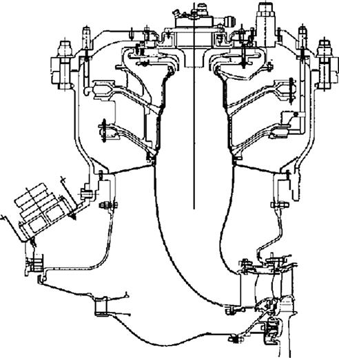
The engine incorporates a dry, low-emissions (DLE) cannular-type combustor, a cross-section of which is shown in Figure 4–56. Fuel and air are mixed in three separate manifolds, referred to as the primary, secondary, and tertiary premixers. The combustor is a staged design, where only the primary is self-stabilized; that is, it can operate alone. The primary therefore provides the combustion stability required during instances such as fast transient maneuvers as it ensures that the combustor remains lit. The secondary and tertiary are each ignited by their respective upstream stage.
This allows the secondary and tertiary to be operated at a much lower flame temperatures than is normally required for flame stabilization. Consequently, a large turndown ratio is possible for the secondary and tertiary fuel/air ratios.
The combustor design also gives a high degree of flexibility in fuel scheduling, as the primary and secondary temperatures can be controlled independently with the tertiary taking the balance of the total fuel. The relationship between combustor inlet and outlet temperatures can vary considerably by daily condition. This means that the primary, secondary, and tertiary fuel schedules, which are set to give the best possible performance for each day’s condition, can vary considerably as well.
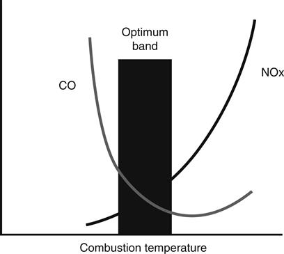
One of the main challenges in DLE design is to meet the required emissions targets while at the same time avoiding thermoacoustic resonance. As shown in Figure 4–57, as the flame temperature increases, the NOx level increases, as the flame temperature decreases, the level of CO increases. The result of this relationship is that the fuel must be controlled in such a fashion that the flame temperature is controlled within an optimum band, which is generally agreed to be around 1850 K.
As with most other DLE-type combustors, the industrial Trent fuel system must have sufficient fuel metering flexibility and accuracy to manage a variety of requirements (including thermoacoustic resonance, emissions, combustion hardware thermal loading, etc.).
In addition to metering the fuel accurately, the delivery system must also meet stringent repeatability requirements. This is due to the need to reliably deliver the required amount of fuel given the same set of input conditions. If the fuel delivery system did not possess a high degree of repeatability, the scenario could arise where the fuel schedules would have to be frequently adjusted to compensate for changing input conditions, such as changes in ambient temperature.
The fuel delivery system must also provide capability to vent the fuel manifolds during fast transient maneuvers in order to prevent undesired fuel flow to the engine. Minimal pressure loss across the system is also a design requirement, as the higher the pressure loss across the delivery system, the higher is the pressure that the gas supply system must provide.
Fuel Flow Metering
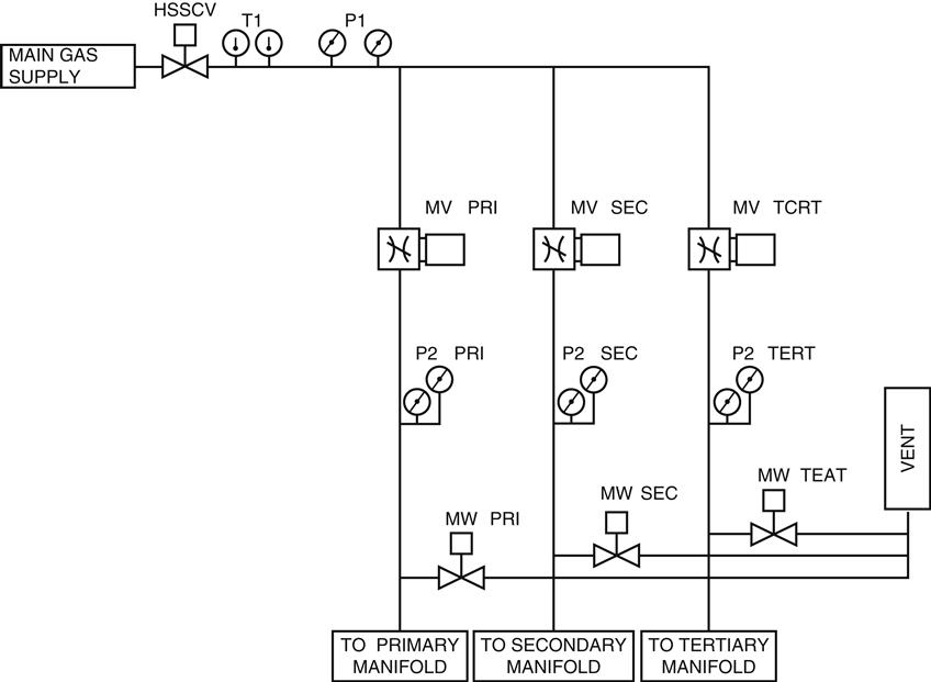
Combustor flame temperature is controlled by accurately metering fuel flow through the three fuel legs. The method of flow measurement chosen for the Trent gas fuel system (Figure 4–58) is based on the principle of the differential producer (pressure drop across a restriction). In this application the primary element (restriction) is the fuel-metering valve.
Other methods of fuel metering were investigated and discarded due to specific application weaknesses. Coriolis meters are known as highly accurate tools for direct mass flow measurement; however, signal noise, vibration sensitivity, and cost of redundancy were the factors that prevented their use. Thermal mass flow meters were not used because the high time constant of the device would not allow adequate dynamic control of the fuel system. Measurement of flow across a venturi was also studied, but the lack of flexibility in the case of fuel schedule changes prevents the use of this method.
Upstream pressure, upstream temperature, downstream pressure, fuel composition, and valve Cd must be precisely known to provide accurate fuel flow metering. Pressure measurements are made using transducers that were originally developed for the aerospace full-authority digital engine controls (FADEC). The transducers have an accuracy of better than ±0.5 psi from 5 to 1000 psia. Fuel temperature is measured using a high-accuracy platinum RTD and fuel composition is measured using a spectral gas analyzer.
Using the valve as the primary element requires that valve positioning be very accurate and that the valve discharge coefficient be precisely known for a wide range of flow conditions. The metering valves are positioned with a brushless servomotor and position feedback is provided by dual revolvers. Closed-loop position control is better than ±0.2% of valve stroke.
Fuel Shutoff and Venting
Upon a load rejection the fuel metering valves can slew from open to closed in under 125 milliseconds if required. In addition, manifold vent valves quickly open to rapidly drop pressure in the fuel manifold, stopping fuel flow into the combustor. Rapid and precise venting of the fuel, combined with fast and accurate fuel flow control using the fuel metering valves, is an important factor in allowing the Trent to be smoothly brought to synchronous idle speed after a high power load rejection.
In the case of an emergency shutdown, the high-speed shutoff valve (HSSOV) will quickly block off the main fuel supply. Simultaneously the fuel metering valves will close and the manifold vent valves will open. This manages the deceleration control requirements.
The manifold vent valves and HSSOV must have a high flow capacity with a very low-pressure drop. They are also required to shift to the safe state in less than 100 milliseconds.
Fuel Metering Optimization
For all turbine applications it is important to minimize pressure drop across the fuel delivery system. Pressure drop across the metering system represents losses in energy due to higher supply pressure requirements. This can also increase the initial investment in the form of larger fuel-compression hardware. The high compressor ratio of the Trent turbine (40:1) makes minimizing pressure losses in the fuel delivery system essential.
Measuring flow across a differential producer requires that there is a pressure drop across a restriction and that this pressure drop is measured accurately. To accomplish this while minimizing fuel system pressure drop, accuracy of the pressure measurements is critical. This drives the use of very-high-accuracy pressure transducers and an understanding of well-established standards for measuring flow across a differential producer.
During development of the fuel system, minimizing cost was a key objective of the design team. Flow measurement standards define the location for pressure measurement relative to the restriction. This requires pressure measurement at the inlet and outlet of each metering valve. Redundancy requirements drive the use of two transducers at each pressure measurement location. Two pressure transducers at each measurement point on three metering legs means that 12 pressure transducers would be required in total. Twelve very-high-accuracy pressure transducers would represent a high cost element of the gas fuel system.
To reduce cost for the system, P1 measurement for each leg is made at a common point on the inlet fuel header. This lowered the number of pressure transducers from 12 to 8. Measuring pressure away from the valve inlet has the potential of reducing flow-metering accuracy, so analysis was conducted to minimize the pressure difference between the header pressure port and that at the inlet of each valve. Analysis was conducted for all ambient conditions under worst-case fuel conditions. Several iterations were made to find that a 3 in. header feeding the 2 in. fuel metering legs provided the smallest error. This arrangement also provides very low-pressure losses.
The manifold is designed to minimize P1 measurement error; however, the flow accuracy requirements demand tighter P1 measurement accuracy. This is further complicated because the production metering valves are calibrated with P1 pressure measurements at the inlet of the valve. To achieve flow accuracy while measuring pressure at a common header port, an algorithm was devised to correct header pressure measurement to the pressure that would be measured at each of the legs. This algorithm is implemented in the control and is an integral part of the flow control loop.
To meet the flow accuracy metering requirements and to provide good dynamic control, the minimum pressure drop across the metering valves is 50 psid. Additional sources for pressure drop are the HSSOV, the inlet manifold, and the outlet spool pieces. The design is such that the pressure ratio across the fuel system is minimized as much as possible.
Summary
The industrial Trent gas fuel system provides highly accurate and repeatable fuel metering for a wide range of flow conditions. The system meets aggressive targets for pressure loss and cost and offers high parts commonality despite having to meet a wide variety of flow requirements. Reliability was not sacrificed at the expense of cost, as the fuel system incorporates a high degree of redundancy.
Testing on the Woodward flow rig allowed a high degree of confidence to be achieved in the system as it gave the opportunity to test the valves under conditions representative of engine operation. Use of the flow rig provided a method of mapping the system to provide extremely accurate and repeatable flow control.
Case Study 2: Dry Low Emmissions (DLE) Combustor System Application (Thyphon)7
The first Typhoon generator set fitted with ABB Alstom Power's dual fuel dry, low-emissions system entered service in June 1998 at the Boots Company headquarters in Nottingham, England. Running on distillate fuel NOx emissions of 30 ppmvd at 15% O2, they have been commercially demonstrated without water or steam injection. This section describes the operating experience gained from the gas turbine manufacturer's and operating customer's points of view. The gas and liquid fuel burner configurations along with the operating concept are described. Discussion of the initial site issues encountered, the solutions introduced, and the effect on operational impact are then explained in detail.
End-User Profile
Today the main Boots site is located at Beeston to the west of Nottingham. The site covers 300 acres and contains over 100 individual buildings. In the region of 7000 people are employed on the site. A number of different activities are carried out on site, including:
• Consumer and health-care product manufacture and development
• Warehouse and goods distribution
The site has had its own power station since the development of the site in 1928 when the powerhouse was constructed. Steam and electricity were provided initially from two coal-fired boilers supplying steam via a 1 MW back pressure turboalternator. As time progressed the powerhouse was developed as site activities expanded and its energy requirements increased.
By 1996 what had evolved was a highly complex powerhouse that could raise steam by coal, gas, gas oil, or heavy fuel oil and generate electricity by gas turbine or steam turbine using either back pressure or condensing turbines. The gas turbine plant comprised two Ruston TA1750s and a TB5000.
This combination of plant led to an operation that had become uneconomical, with high maintenance and operating costs, and some plant was coming to the end of its useful life. The powerhouse operation was also regulated by Her Majesty’s Inspectorate of Pollution (HMIP) under the Environmental Protection Act (EPA) of 1990 and required an Integrated Pollution Control (IPC) authorization to operate. The station’s authorization to operate contained a number of improvement notices, one of which was to investigate NOx reductions on gas turbine and boiler plant for improvements by April 1997.
The requirement to improve the environmental impact of the powerhouse initiated a feasibility study that led to the design, construction, and commissioning of a new combined heat and power (CHP) energy center. The salient parts of the new energy center comprised:
Gas Turbine Procurement
Procurement of the gas turbines started in the summer of 1995. At the time dry, low-NOx reduction on circa 5 MW turbines was not as well advanced as in larger engines. However, Boots was aware that dry, low-NOx techniques represented the best available technology (BAT) solution and as such were keen to pursue this route. NOx reduction by steam injection was an option, but in this case was not a practical solution since the steam raised within the CHP was not of sufficient pressure or quality.
Subsequent gas turbine tender evaluation revealed that dual-fuel DLE was commercially available in only one circa 5 MW turbine and in our opinion the UK support for this engine was not satisfactory.
Discussions with ABB Alstom Power (then European Gas Turbines) revealed that it was undertaking a development program to provide dual-fuel DLE capability for the Typhoon. At this stage ABB Alstom Power was anticipating availability by summer of 1998 with guaranteed NOx emissions of 25 ppmvd on gas and 85 ppmvd on gas oil (at 15% O2). With this in mind Boots approached HMIP and gained dispensation to run uncontrolled engines until September 1, 1998, by which time the turbines must be retrofitted with DLE technology. This requirement was subsequently incorporated as an improvement notice into the energy center’s IPC authorization to operate.
A contract for three 4.9 MWe Typhoons was awarded to ABB Alstom Power, which included the retrofitting of DLE technology when commercially available. In view of this ABB Alstom Power brought forward the development program in order to meet the agreed time scales.
The three Typhoons were installed during the summer of 1996 and commissioned in the autumn with the new energy center fully operational by the end of the year. Each of these has since accumulated over 20,000 operating hours.
Dual DLE Burner
ABB Alstom Power has successfully completed over 750,000 operating hours with its G30 dry, low-emission combustion technology on Typhoon 4.35 MWe, 4.7 MWe, 5.05 MWe, and 5.25 MWe gas turbine engines. The single-shaft generator sets have guaranteed NOx and CO emissions of less than 25 ppmvd when operating on natural gas fuels and less than 50 ppmvd when operating on distillate 2 fuels (at 15% O2). The DLE combustion system was designed to retrofit into existing diffusion flame Typhoon engines in minimum time and with minimum operating impact. The units have been designed to offer a dual-fuel starting capability for greater customer flexibility, particularly on offshore installations where initial commissioning requires power without gas fuel supplies. CO emission (below 50 ppmvd) turndown to 70% engine load on gas fuel and 65% on liquid is achieved using modulation of the compressor variable guide vanes.
Three main combustor parameters are measured to monitor the engine and combustor health. These are:
• Pilot tip temperatures. Each pilot burner assembly has a thermocouple positioned behind the pilot burner front face; this is used for ignition recognition and ensures that the face temperature is acceptable.
• Combustor dynamics. Engine flame front pressure fluctuations are monitored using a PCB transducer connected to the combustor pressure casing.
• Exhaust gas temperature profile. There are a number of thermocouples situated downstream of the turbine exit to monitor the gas temperature for deviation from normal.
Burner Concept Design
The premix burner design consists of 12 radial inlet slots configured to allow a predetermined amount of air into the main head of the combustor can. The air swirler inlet vanes are of the same dimensions and are positioned in order to create a swirling vortex. A considerable amount of analytical design (including CFD) and test evaluation was carried out in order to determine the correct number of swirler vanes, their thickness, the size of air passage way, and the elimination of any recirculatory zones or wakes from the trailing edge of the “cheese slice” shapes. Substantial testing of this design was carried out in order to optimize fuel placement while avoiding undesirable factors like fuel impingement on combustor walls and burner slot faces. The optimization of these parameters led to a design that is inherently safe against flashback, and since the main fuel supply is introduced into these “mixing slots” with their high velocities, excellent homogeneous air fuel mixtures exist at the operating condition. Production of a cone-shaped flame that is anchored onto the pilot face therefore produces a simple while robust flame. Anchoring of the flame on the pilot face allows for acceptable levels of combustion noise; low levels of combustion noise when operating on either gas or liquid fuel produce an advantageous environment for combustion hardware life and lead to long-term durable turbine usage.
Dual-Fuel DLE Burner Configuration
The dual-fuel DLE burner is composed of a two-stream gas and two-stream liquid fuel system, both systems being operated by independently controlled electrically actuated valves. The premixed main fuel flame is supported during starting and transients with a pilot (gas) or primary (liquid) fuel input, which can be separately configured at full load for various ambient temperatures or local emission requirements. Cross-light tubes have been removed from the DLE combustion cans in order to limit emissions; this gives a requirement for individual ignitors mounted in the pilot body which emerge onto the pilot face. Purging systems assist in keeping non-operational pilot fuel injector ports free from blockage. The main fuel injector ports, due to their position within the burner swirler, do not require any purging.
A single air-assisted primary nozzle is used in each combustor to initiate liquid fuel ignition and to support the main premixed fuel during running.
The primary or pilot flame assists the premixed zone stability during engine transients and can be adjusted using the control panel in order to adjust emissions for the local requirements when running. This task is carried out while monitoring pilot tip temperatures, as pilot split variations can have a marked effect on the component temperature. Configurable maps allow pilot percentage changes to be made easily and quickly. This is normally carried out during final commissioning with continuous emission monitoring (CEM) and combustor dynamic monitoring (FFT) equipment.
DLE Retrofit
During the dual-fuel DLE program Boots was kept informed of the development progress and attended regular update meetings with ABB Alstom Power. Originally Boots had hoped to embark on the retrofit program only when the technology was commercially available and proven in the field. However, due to the September 1, 1998 deadline it became necessary for Boots to commit to being the first site to have dual-fuel DLE installed on a Typhoon. This decision followed extensive talks with ABB Alstom Power and relied on the successful demonstration of dual-fuel operation. However, at this stage work was still progressing on fuel changeover at the ABB Alstom Power site in Lincoln.
While a DLE retrofit can take place without core removal, the retrofit at Boots was planned to coincide with the planned two-year service; therefore a rolling core change-out approach was taken. Each change-out was planned to take eight weeks although it was accepted at the time this was very optimistic as the retrofit involved significant work for both ABB Alstom Power and Boots.
The ABB Alstom Power scope of work included:
• Rolling change-out of the engine core with a core fitted with the DLE combustion equipment
• Replacement of the existing fuel systems with the new DLE fuel system
• Control hardware and software upgraded to DLE standard, including additional I/O
The Boots scope of work included:
• Installation of additional interface cabling between the skid and turbine control module
• Modifications to the fuel supply lines
• Installation of an extensive vents and drains system
• Provision of additional compressed air supplies for purging
• MCC modification associated with change from dc to ac ignitors
• Re-engineering of the MODBUS interface to the station distributed control system and the associated turbine graphical displays
The first engine (GT1) was shut down on March 27, 1998 to facilitate the conversion. During this time electricity had to be imported due to the lost generation and additional steam had to be raised on the package boilers. This had a significant financial impact on the business, and as such, it was essential that the work was completed in minimal time.
The retrofit work on GT1 was completed on May 22, 1998, and commissioning started with the first start on gas fuel occurring towards the end of May. Subsequent work demonstrated turbine operation on both gas and liquid fuel including load shed and fuel changeover. However, at this stage ABB Alstom Power were unable to demonstrate liquid starting successfully due to liquid-air-assist supply-side contaminants. Emissions performance was demonstrated successfully using mobile continuous monitoring equipment set up on site by ABB Alstom Power, the results of which were compared with Boots-installed continuous monitoring equipment. On June 10, 1998, Boots accepted GT1 despite the liquid fuel starting restriction for a seven-day reliability run. Following successful completion of the reliability run, GT2 and GT3 retrofits followed.
The final turbine was shut down on August 28, 1998, just prior to the September 1 deadline after which Boots IPC authorization did not permit operation of uncontrolled engines. The work had taken longer than planned, particularly on GT1 due to a number of reasons, including:
• Delivery of essential new DLE parts
• Physical limitations of technicians working within the turbine skid
• Additional vents and drains system
• Turbine exhaust gas leakage from waste-heat boiler ductwork. This was not attributed to the turbine but delayed commissioning of GT1.
During the retrofit program it became apparent that there was also a reliability problem with starting on gas fuel. ABB Alstom Power were able to assure Boots that the gas starting reliability would be resolved by the implementation of a software change that had been proved on the test bed and was undergoing final software validation. In the meantime, starting could be achieved but required the engine to be closely monitored by a field technician. This never affected operations but resulted in ABB Alstom Power maintaining a daytime site presence to ensure high turbine availability.
Commercial Operations Post Retrofit
Gas Starting Reliability
The gas starting reliability was resolved by the installation and commissioning of revised software modules incorporating a new starting philosophy and an improved method of detecting “flame on.”
Restriction of Liquid Operation
Problems with liquid running meant that operation was restricted to gas fuel in November 1998. Boots has an interruptible gas contract and as such is susceptible to gas interruptions during the winter months, particularly January and February. It was therefore essential to have liquid fuel operation available for this period. Careful planning between Boots and ABB Alstom Power allowed the remedial work to be carried out during weekends in December and during the Christmas holiday period. This ensured liquid fuel operation was available for January while minimizing the financial implications of the turbine outages. Liquid starting was still not available, but reliable fuel changes could be easily achieved.
Liquid Starting
Initial observed starting problems were traced to contaminant blockage of the air-assist system. Following successful testing and validation of an improved purge system, retrofit kits were installed to the three turbines during September 1999 with the work on each turbine being completed over successive weekends. Currently during summer weekends only two turbines are required for optimal economic operation, the work was therefore completed without effecting commercial operation of the energy center.
Availability and Reliability
As has been discussed a number of issues were encountered under normal site operating conditions with the dual-fuel DLE systems that resulted in lost generation while problems were investigated and subsequently resolved. In the majority of instances Boots was able to accommodate the required outages for the remedial work during weekends or holiday periods when the commercial effects could be minimized. Putting aside the outages required to accommodate the remedial work availability has been high and running reliability has been excellent with no notable shutdowns due to the DLE technology.
Emissions
The reduction in total NOx mass emissions from the three Typhoons at the Boots energy center is shown in Figure 4–59. The graph shows clearly the significant environment improvement that the retrofit has achieved. An additional important benefit of the retrofit is the absence of any visible plume from the chimney on both gas and liquid fuel.
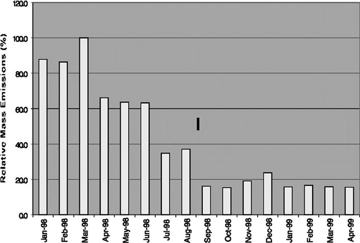
Solutions to Initial Operating Issues
Initial running of the dual-fuel units in the field under normal operating schedules highlighted several combustion shortcomings resulting in undesirable fuel leakages of the main and pilot burners. The following is a description of the findings and the work carried out to overcome the operational difficulties.
Main Air Swirler—Issue 1
The main burner with its integral gas and liquid fuel galleries is a multicomponent part. The various assembly bolts have been carefully positioned to hold the combustor can and retain the fuel gallery integrity. During production works testing the cores demonstrated repeatable and stable fuel changeovers in both directions with no deterioration in emissions. During extended site running it was noticed that the emissions were exhibiting a step change in the NOx after consecutive fuel changeovers. Inspection of the main fuel burner highlighted that the gas gallery seal was leaking due to distortion of the swirler plate base. This led to premature gas injection upstream of the air swirlers and undesirable misplaced fuel positioning. NOx emissions would gradually increase with successive fuel changeovers and pilot tip temperatures would rise. Operational limitations were due to high tip temperatures and the units were restricted to running on gas fuel.
Solution to Issue 1
Revised manufacturing heat treatment methods and a more comprehensive leak check process were implemented; successful and repeatable emissions have now been demonstrated over a long period of operation, as shown in Figure 4–60.
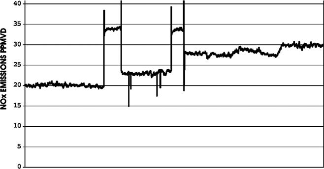
Pilot Liquid Fuel Lances—Issue 2
The pilot burner houses both gas and liquid fuel galleries for each combustion chamber. Gas is channeled to the outer diameter of the pilot while the liquid is transported through lances to the pilot face. Initial design consideration for the lances suggested a screwed connection, which would simplify exchange and overhaul; however, repeated problems were encountered with leakage at the base of the lances (Figures 4–61 and 4–62). Subsequent contamination of the pilot tip thermocouple with liquid fuel would lead to very high indicated tip temperatures due to boiling off of the fuel just beneath the pilot face. Liquid operation would be possible up until the point where the lances would leak; this problem occurred randomly.
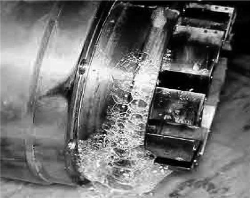
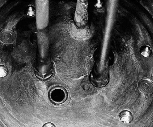
Solution to Issue 2
In order to overcome the leakage the lances were brazed in during the manufacturing process, instead of relying on a screwed connection. A sealing compound was also applied between the manifold block and the pilot cap to stop the hydraulic ingress of liquid fuel into the tip thermocouple hole.
Air-Assist Supply—Issue 3
Initial commissioning of the liquid fuel system showed reliable ignition and successful liquid starting capability. Continuous operation with intermittent water washing over a period of several months would see a reduction in the reliability of the liquid ignition performance, while fuel changeovers were operational and unaffected. Subsequent examination of the burners revealed that the air-assist porting just prior to the liquid entry into the combustor chamber (Figure 4–63) had accumulated debris from the instrument air or compressor purge system. Subsequent analysis showed compressor dirt and pipe manufacturing debris would travel along the purge system after continuous running and deposit itself in the critical swirl entry ports seriously impairing the atomization performance.
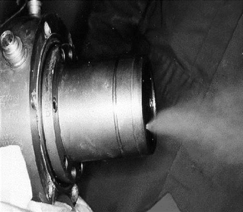
Solution to Issue 3
The development work carried out to overcome this difficulty centered on an improved purge system using finned cooling pipe lengths, which offered a reduced pressure drop and used an inline main filter and individual last-chance burner filters. In stopping the debris from reaching the atomization entry ports, it was found that liquid ignition reliability did not deteriorate with running time. Implementation of this improvement has now been completed on all three units.
Starting Improvements—Issue 4
Original ignition philosophies of increasing engine crank speed while inputting a constant fuel flow showed that, during adverse ambient temperature changes, the unit would miss the ignition window. This was easily corrected by fuel light flow adjustments; however, it did require a field support visit and missed valuable running time for the customer.
Solution to Issue 4
A new starting philosophy was developed using a fixed crank speed and a variable fuel flow ramp, the range of fuel flows was set large enough to counter the air density changes encountered at adverse weather sites. Can “flame-on” monitoring using the pilot tip thermocouples showed a marked increase in light-up reliability; previous software attempted to interpret power turbine exit temperatures and to equate this rather transient condition to can lit indications. Ignitor durability improvements and revised gas valve drive couplings and calibration methods also improved startup repeatability. These improvements have now been installed and have led to increased start reliability.
Combustor Dynamics Measurements
Acceptable combustion dynamics or flame front pressure oscillations are critical if mechanical integrity of the combustion hardware is to have a long life. Mechanical life is closely related to the amount of energy produced by a combustion system, by using a relatively small and robustly constructed combustion can with unique design features, acceptable levels of combustion noise have been demonstrated.
Adjustment of the amount of pilot or primary fuel inputs assist in stabilizing the flame, adjusting the pilot face temperatures, and changing the level of emissions. Optimum settings for all three parameters can be achieved during final site commissioning. When operating on gas fuel the pilot is set up in order to just meet emission obligations, with typical pilot splits around 7–10% of total fuel flow. The split of the pilot is set at these relatively high levels to ensure all year round flame stability and good transient capabilities. When operating on liquid fuel the primary fuel split is typically set around 4–6% of total fuel flow. Pilot tip temperatures when operating on liquid exhibit a more sensitive characteristic than when operating on gas with respect to pilot/primary adjustments.
Figures 4–64 and 4–65 show typical plots of the readings obtained while running on gas and liquid fuel at full load. Dynamics measurements while running at full load with gas fuel generally exhibit sub-100 mpsi peaks while with liquid fuel sub-300 mpsi peaks are evident.
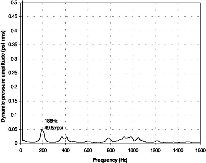
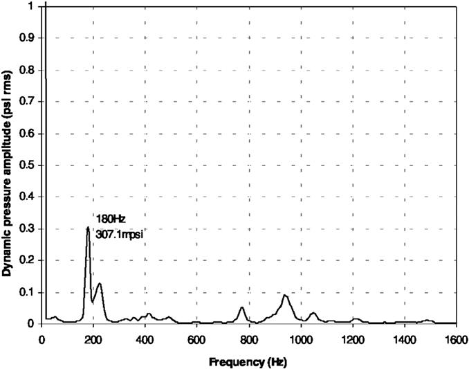
Operating Milestones
At 12,000 hours commercial operation (December 1999) on the lead engine with ABB Alstom Power’s dual-fuel DLE system found the following results:
• Demonstrated NOx emissions of 20 and 30 ppmvd at 15% O2 on gaseous and liquid fuels, respectively. This allows for emission guarantees for NOx of 25 ppmvd at 15% O2 when operating on gas and 50 ppmvd at 15% O2 when operating on liquid fuel.
• Operation on both fuels over total load range with acceptable pilot tip temperatures and combustor dynamics.
• Establishment of combustion hardware life and life extension programs.
• Establishment of commissioning procedures for future DLE dual-fuel units.
In summary, ABB Alstom Power’s G30 dry, low-emission Typhoon is a dual-fuel system that is capable of delivering around 30 ppmvd NOx while running on liquid fuel. Reliable fuel changeovers and liquid starting capability have now been allied to a proven low-emission gas system in a compact power generation unit. The DLE retrofit has demonstrated the performance of the DLE technology and given substantial reduction in NOx mass emissions at the Boots site. As can be expected with the introduction of such technology for the first time, a number of issues arose. These presented ABB Alstom Power with a number of technically interesting challenges, solutions for which have been validated on the core engineering’s development facilities. The major achievement of this work has been to demonstrate that very low emissions operating on distillate fuel without water or steam injection is a commercial reality (Figure 4–66).
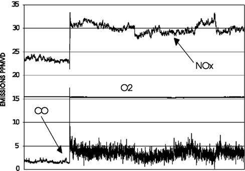
Case Study 3: Another DLE Application (Former Model Designation Tempest)8
Following the experience gained on the Typhoon generator set, Alstom Power’s generic dual-fuel dry, low-emissions combustion system has been successfully developed for operation on the Tempest generator set. The first engine fitted with the full DLE dual-fuel system entered service in October 2000.
NOx emissions levels of less than 30 vppm at 15% O2 have been demonstrated on distillate fuel. This section describes the development of the dual-fuel DLE system on the Tempest as well as the commercial operating experience gained to date on both the full dual-fuel DLE and liquid standby DLE systems. The commercial operating experience will cover areas such as operating concept, liquid starting reliability, and site issues encountered. The lead Tempest gas-only DLE units have successfully completed 22,000 hours of operation.
Emission guarantee levels are set at less than 25 ppmvd on NOx down to 65% load when operating on gas fuel and 50 ppmvd on NOx down to 60% load when operating on liquid fuel. CO turndown guarantee levels are 50 ppmvd down to 65% load on gas fuel and down to 60% on liquid fuel.
Development of Dual DLE Tempest
The Tempest gas turbine engine was launched in 1995. The engine is a single-shaft configuration producing 7.7 MWe for the electrical power generation market. Initially offered with either conventional (diffusion flame) gas-only/dual-fuel or gas-only DLE(3), applications for dual fuel operation with DLE configuration were met with gas DLE and a liquid capability, but without any emissions compliance, referred to as gas DLE + LSB (liquid standby). Table 4–1 shows the Tempest’s operating conditions.
High-Pressure Rig Test Work
By the end of 2000 the Tempest fleet consisted of 38 engines, 20 of these configured for DLE operation. To recognize the need for liquid fuel capability, the requirement for a dual-fuel DLE variant was confirmed.
The Tempest dual-fuel DLE combustion system consists of six reverse flow canular combustion chambers that are connected to the center casing by means of six individual transition ducts. The dual-fuel version uses the same combustion cans and transition ducts as the gas-only version. Figure 4–67 illustrates the pilot burner and main burner including liquid core comprising the main liquid nozzles, and combustion chamber.
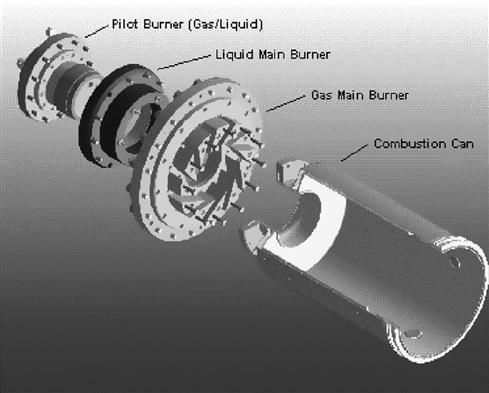
As with the gas-only version, the dual-fuel combustion system uses a lean premix burner to control the flame temperature at levels that limit thermal NOx formation. A central pilot burner is used for ignition and flame stability.
Prior to engine test development of the combustion system, a series of tests were performed on a single combustor high-pressure test facility. The main objective of the high-pressure rig work was to establish the optimum size and configuration of the liquid fuel nozzles as well as establish an operating regime with respect to pilot split and combustion dynamics.
The main liquid fuel nozzles were investigated first. The nozzle size chosen was scaled from the Typhoon dual-fuel combustor. This gave the minimum flow number, maximum fuel jet penetration possible without compromising the fuel nozzle passage size. This nozzle size equated to a six main fuel nozzles per burner configuration as with the Typhoon combustor. Using this main fuel nozzle size a variety of tests were conducted using from 3 main fuel nozzles per burner up to 12 nozzles. From this it was concluded that using less than six main nozzles compromised the stability of flame particularly at lower loads, while more than six nozzles gave poor fuel jet penetration which in turn was shown by the high pilot burner tip temperatures and eventual damage of the pilot burner face. Therefore the final configuration of six main fuel nozzles was selected.
The circumferential position of the liquid main nozzles was also investigated by testing two configurations. The first was scaled from the Typhoon combustor and the second to give a similar circumferential position to that of the proposed Cyclone dual-fuel combustion system. The test proved that the circumferential position of the main fuel nozzle in a Tempest-size combustor had no effect on the stability, emissions, or burner component temperatures.
The liquid standby version of the Tempest has five liquid fuel nozzles in the pilot burner. All nozzles have the same flow number with one being an ignition nozzle with air assist. For the starting point for the dual-fuel testing the liquid standby ignition nozzle was used. This nozzle had already been proven successful in engine operation for ignition and following the rig tests proved satisfactory for flame stabilization in conjunction with a six main nozzle per burner configuration. A lower flow number ignition nozzle (35% lower flow number) was also tested with the view to improving smoke emissions and light-up reliability by having improved atomization with the higher-pressure, lower-flow-number nozzle. Light-up reliability and smoke emissions at pull-away and low-load operating conditions are not measured on the high-pressure (HP) test rig due to the fact that the engine operating conditions cannot be simulated close enough to give reliable information. This proved unacceptable for engine operation as the amount of pilot required at reduced load to ensure flame stability would not be achievable due to a limit on skid-edge fuel pressure. Therefore the final configuration of one ignition nozzle (standard nozzle) per pilot burner with the same flow number as the liquid standby ignition nozzle was selected.
Engine Development Test Work
A Tempest core was fitted with a set of dual-fuel pilot and main burners, based on the best configuration proved on the HP rig. No alterations were required for the fuel system to accommodate the dual-fuel testing, as the existing liquid standby system was compatible, which gives the option for fairly easy conversion of liquid standby systems to full DLE dual fuel.
The initial testing was performed on gas fuel in order to compare the performance of the dual-fuel version with the gas-only version. Using the standard settings for light-up, pull-away, and load running from the gas-only and liquid standby engines, the full dual-fuel DLE hardware gave good startup and pull-away reliability. Emissions, burner component temperatures, and combustion dynamics were then measured throughout the load range, with all parameters giving similar levels to those expected. NOx emissions at full load with a standard pilot split was 22 ppmvd @15% O2.
Completion of the initial gas fuel operation was followed by light-up performance optimization on liquid fuel. As the ignition nozzle being used was identical to that used in the liquid standby burners, the liquid light-up settings, for example fuel pressure, air-assist pressure, fuel ramp rates, and pilot split, were all known. It was found that by increasing the air-assist pressure the ignition reliability was reduced. One reason for this reduction in reliability on ignition with increasing air-assist pressure was noted when visually checking the spray quality on the calibration rig. When the air-assist pressure was increased the spray cone narrowed and lifted further away from the area where the ignition source was, thus reducing the chances of successful light-up. One alteration to the pull-away on the full dual-fuel version was the need to increase the amount of pilot split from the corresponding value on the standby engines. This was to allow for good flame stability and acceleration of the engine to idle.
At idle, with the VGVs in their normal open position, the pilot tip temperatures reached mid-800°C, but by closing the VGV on the compressor the pilot tip temperatures reduced by approximately 100°C. This also resulted in improving the CO and smoke emissions levels. The smoke levels recorded indicated that above 50% load UK Bacharach smoke number was 1 and below 50% load was between 3 and 4. Variations in pilot fuel split at idle conditions were completed to optimize emissions. The engine load was increased in stages; at each point the pilot split altered to allow the optimization of emissions, combustion dynamics, and burner component temperatures. This test allowed the VGV position to be modulated manually, keeping them closed until a certain operating temperature was reached then opening them up to maintain this temperature until fully open.
The exhaust emissions achieved at full load showed NOx levels were 34 ppmvd at 15% O2 (Figure 4–68), with CO levels remaining below 50 ppmvd at 15% O2 down to 60% load (Figure 4–69). These are compared in Figure 4–70.
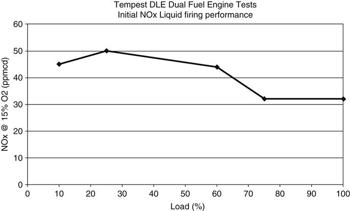
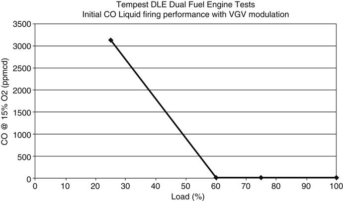
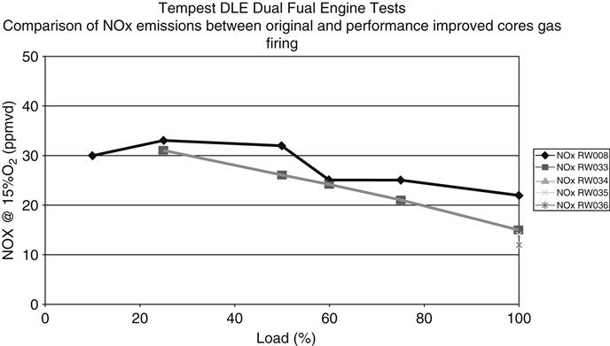
Operational Experience, Gas Only
To date the Tempest has accumulated over 150,000 hours operating the DLE combustion system. The lead engines have both to date completed over 22,000 hours. Regular inspection of the combustion system has indicated the design life of the components has been met. Main burners, combustion cans, and transition ducts are in excellent condition and expected to easily achieve design life. Pilot burner life on these engines has also been extremely encouraging, with 16,000 hours being achieved without component distress being identified. Emissions performance on these engines has also been consistent over the engine life, with guarantee levels still being met comfortably after 22,000 hours, based on there being no change from commissioning through to independent measurements completed at 16,000 hours.
Liquid Standby
Four gas DLE liquid-standby Tempest engines in commercial operation have accumulated over 50,000 hours of operation. The lead engines have both to date completed in excess of 18,000 hours. Like the gas-only engines regular inspections of the combustion system have indicated that all components are in excellent condition and are expected to reach the design life. Estimation of pilot and main burner life has though been effected by oil carryover issues on the lead engines. Both engines have gas supplied via an on-site gas compressor. During the initial period of operation problems were encountered with start reliability and load running. On inspection of the combustion and fuel system it was found that the burners had become contaminated with lube oil, which had been carried through the system from the gas compressors. After installation of coalescers downstream of the gas compressors and replacement of the main and pilot burners, the engines have operated without interruption. Startup reliability on both fuels as well as fuel changeover capability has been available since the installation of these coalescers. Both these units are to be retrofitted to full dual-fuel DLE following the 24,000 hour inspection which is planned for summer 2001.
Dual DLE
In addition to the completion of the standard works test on the first production core with dual-fuel DLE combustion equipment fitted, the core was installed and tested as a complete package before being shipped to the site (Figure 4–71). The combustion system performed as expected with good startup reliability on both fuels, load running on both fuels, fuel changeovers, load accept and rejects on both fuels all being established while operating within the normal package layout against the generator. Following installation at the site the engine package was successfully commissioned during September and performed its acceptance run during October. Emissions measurements taken on-site indicated that the unit was running with a NOx level of around 12 ppmvd on natural gas with a pilot split of 7%. During the first half of 2001 the full load emissions will be optimized to obtain continuous sub-10 ppmvd NOx operation in conjunction with Alstom’s ultra-low-emissions development program. Emissions levels of around 20 ppmvd were measured when running on diesel. Engine light-up reliability on both fuels has so far been met comfortably, with the contractual availability being achieved. At the time of writing this section the engine had accumulated over 2000 hours operation.
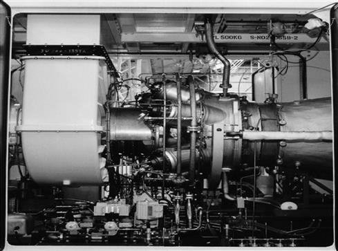
In summary, the G30 dual-fuel dry, low emissions on the Alstom Typhoon gas turbine has been successfully applied and developed on the Alstom Tempest gas turbine engine.
This dual-fuel DLE combustion system has been shown to deliver, reliably, less than 30 ppmvd NOx on liquid fuel accompanied with a NOx emissions performance on gas fuel of less than 10 ppmvd.
Reliable starting on both fuels as well as fuel changeover capabilities are all proven features of this simple yet durable combustion system.
The dual-fuel Tempest has been introduced into commercial operation using the new modularized package.
Case Study 4: DLE Applications in Gas Turbines (30 MW to 180 MW)9
Depending on the amount of by-product gas available and power generation needs, there are three configurations that have been used as of 2007:
• Small gas turbine size (30 MW Class M251)
Commercial operation of the world’s first low-Btu BFG gas turbine (MW-151S) with turbine inlet temperature of 1000°C (1832°F) started in 1982, and was followed by a 145 MW large frame M701D gas turbine operating with BFG commissioned in 1987. After accumulating long-term practical operation both in middle size BFG firing gas turbines and large frame D class gas turbines and combined cycles. The first BFG firing gas turbine combined cycle plant export unit was delivered to UNA in the Netherlands in 1997. MHI further up-rated the low calorie technology to F class gas turbines for BFG firing. The first F class firing BFG with 1300°C (2372°F) turbine inlet temperature started commercial operation for a domestic 300 MW power plant in 2004. This combined cycle includes impressive and unprecedented features such as a 56 meter long single shaft configuration that includes a 87.3 MW centrifugal BFG compressor driven through a step-up gearbox (refer to Figure 4.72).
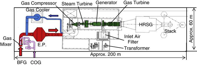
MHI has manufactured numerous plants burning unconventional by-product gases not limited to blast furnace gases. Other gases included Coke Oven Gas (COG), Finex Oven Gas (FOG), hydrogen-rich refinery gases as well as different types of IGCC.
The result of the long experience and the reliable operation results of these high efficiency units have made MHI a leading manufacturer for gas turbines firing low calorie steel mills by-product gases. Table 4–2 lists MHI low calorie experience, including 15 new low-calorie by-product projects that have been recently commissioned or are under construction for China, Ukraine, and steel companies in other countries. This includes the development of a combined cycle in Korea with a gas turbine burning a mixture of different furnace by-product gases.
TABLE 4–2
Experience list of low heating value gas firing
| Customer | Application | Start-Up | Model | GT Unit Rating (Incl.G.C.) | Combined Plant Rating | Fuel Main | Combuster Stand-By | |
| NSC (Nippon Steel Co.) Yahata works |
Power supply | 1958 | – | 850 kw | – | BFG (3.2MJ/Nm3) |
– | Single-can |
| NSC Yahata works |
Power supply | 1964 | – | 4000 kw | – | BFG (3.2MJ/Nm3) |
– | Single-can |
| Sumitomo Metal Co. Wakayama works |
Co-generation (WHB, G-M, BLOWER) |
1965 | MW171 | 15,000 kw | – | BFG (3.1MJ/Nm3) |
– | Single-can |
| Shikoku Elec. Pwr Co. Sakaide PS |
Combined cycle | 1970 | MW301 | 34,000 kw | 225,000 kw | COG (3.1MJ/Nm3) |
Multi-can | |
| Mitsubishi Coal Mining Co. Minami Oyubari Plant |
Co-generation (with air-preheater) |
1970 | MW101 | 9000 kw | – | Coal mine (20MJ/Nm3) |
OIL | Multi-can |
| NSC Kamaishi works |
Combined cycle with existing STs | 1982 | M151 | 16,000 kw | 23,000 kw | BFG (2.8MJ/Nm3) |
OIL | Single-can |
| JFC Steel Co. Chiba works |
Combined cycle (single shaft) |
1987 | M701 | 87,400 kw | 145,000 kw | BFG/COG (4.2MJ/Nm3) |
– | Multi-can with BP-V |
| Mitsubishi Gas-Chemical Co. Mizushima-factory |
Co-generation (WHB) |
1988 | MF111 | 16,250 kw | – | BFG/COG (10MJ/Nm3) |
OIL | Multi-can |
| NSC Hirohata works |
Co-generation (WHB) |
1989 | M251 | 30,200 kw | – | LDG (7.6MJ/Nm3) |
OIL | Multi-can |
| Nissin Steel Co. Kure works |
Combined cycle with existing STs | 1989 | M251 | 32,000 kw | 50,000 kw | BFG (2.9MJ/Nm3) |
– | Multi-can with BP-V |
| Nakayama Steel Co. Funamachi works |
Combined cycle (single shaft) |
1991 | M151 | 15,000 kw | 37,000 kw | BFG/LDG (4.2MJ/Nm3) |
– | Multi-can with BP-V |
| Mizhushima Joint Thermal Power Co. | Combined cycle (single shaft) |
1994 | M501 | 86,250 kw | 145,000 kw | BFG/M (4.0MJ/Nm3) |
– | Multi-can with BP-V |
| Fukuyana Joint Thermal Power Co. | Combined cycle (single shaft) |
1995 | M501 | 86,250 kw | 145,000 kw | BFG/M (4.0MJ/Nm3) |
– | Multi-can with BP-V |
| NUON Netherlands | Combined cycle (single shaft) |
1997 | M701 | 87,400 kw | 145,000 kw | BFG/COG (4.2MJ/Nm3) |
– | Multi-can with BP-V |
| NSC Ooita Works |
Combined cycle | 2001 | M251 | 31,000 kw | 65,000 kw | BFG (2.9MJ/Nm3) |
– | Multi-can with BP-V |
| Nippon Petroleum Co. Ltd. Negishi Refinery |
Combined cycle (single shaft) |
2003 | M701F | 301,000 kw | 431,000 kw | Syn gas+N2 (5.9MJ/Nm3) |
OIL | Multi-can |
| Kimitsu Cooperative Thermal Power Co. | Combined cycle (single shaft) |
2004 | M701F | 180,700 kw | 300,000 kw | BFG/COG (4.4MJ/Nm3) |
– | Multi-can with BP-V |
| Zhangjiagang Hongchang Plate Co., LTD., China | Combined cycle (multi shaft) |
2006 | M251 | 30,000 kw | – | BFG/COG (3.1MJ/Nm3) |
– | Multi-can with BP-V |
| Aanshan Iron & Steel Co., Ltd., China | Combined cycle (single shaft) |
2006 | M701F | 183,000 kw | 300,000 kw | BFG/COG (4.4MJ/Nm3) |
– | Multi-can with BP-V |
| Maanshan Iron & Steel Co., Ltd., China | Combined cycle (single shaft) |
2006 | M701DA | 91,300 kw | 153,000 kw | BFG/COG (4.4MJ/Nm3) |
– | Multi-can with BP-V |
| Handan Iron & Steel Group Co., LTD., China | Combined cycle (multi shaft) |
2006 | M251 | 30,000 kw | – | BFG/COG (3.1MJ/Nm3) |
– | Multi-can with BP-V |
| Clean Coal Power R&D Co., Ltd. Nakoso | Combined cycle (single shaft) |
2007 | M701DA | 129,200 kw | 250,000 kw | Syngas (4.2MJ/Nm3) |
– | Multi-can |
| Posco, Korea | Combined cycle (single shaft) |
2007 | M501DA | 88,100 kw | 146,000 kw | FOG (−) |
– | Multi-can with BP-V |
| Lianyuan Iron & Steel Group CO.LTD | Combined cycle (multi shaft) |
2007 | M251 | 30,000 kw | – | BFG (3.1MJ/Nm3) |
– | Multi-can with BP-V |
| Baotou Iron & Steel Co. | Combined cycle (single shaft) |
2007/2008 | M701DA×2 | 82,500 kw | 1380,00 kw×2 | BFG/COG (4.4MJ/Nm3) |
– | Multi-can with BP-V |
| Anshan Iron & Steel Group Co., Ltd | Combined cycle (single shaft) |
2008 | M701DA | 89,7000 kw | 151,000 kw | BFG/COG (4.4MJ/Nm3) |
– | Multi-can with BP-V |
| Ukraine/OJSC Alchevsk Iron & Steelworks | Combined cycle (single shaft) |
2009 | M701DA×2 | 89,700 kw | 151,000 kw×2 | BFG/COG (4.4MJ/Nm3) |
– | Multi-can with BP-V |
| Taiyuan Steel Co. Ltd. | Combined cycle (multi shaft) |
2008 | M251 | 30,000 kw | – | BFG (3.1MJ/Nm3) |
– | Multi-can with BP-V |
| Confidential | Combined cycle (single shaft) |
2009 | M701DA | 89,700 kw | 151,000 kw | BFG/COG (4.4MJ/Nm3) |
– | Multi-can with BP-V |
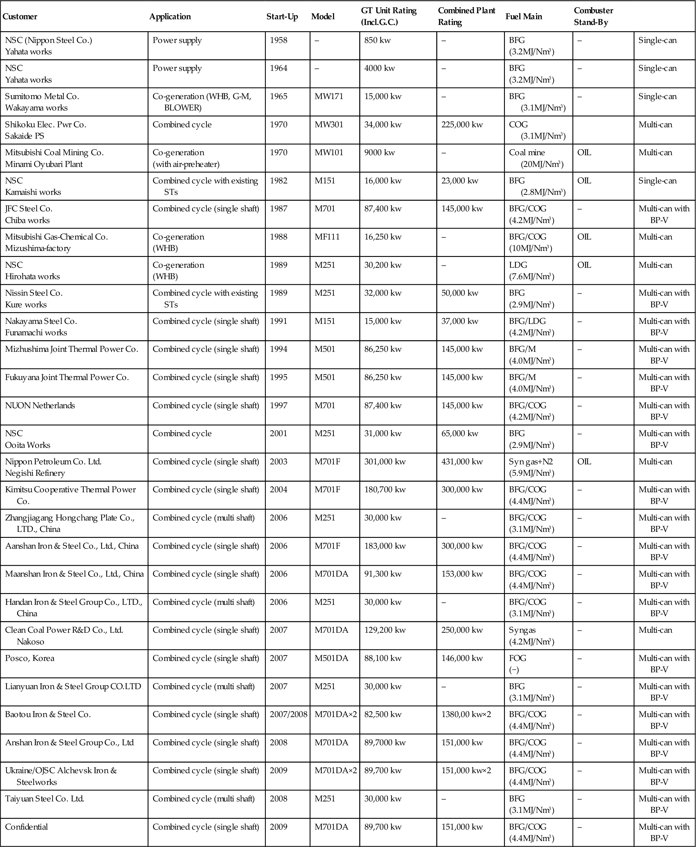
Combustor Design Considerations for Low BTU Fuel Application
Compared to burning natural gas firing, the efficient combustion of low calorie fuel presents several difficult challenges:
• Reduced flammability limits → fuel air ratio in the combustion area is critical.
• Reduced flame speed → the flow speed in the combustion area must be reduced.
• Higher combustion air requirements → potentially high combustor metal temperature due to less cooling air.
On the other hand, the thermal NOx level is low, because of the lower adiabatic flame temperature associated to the combustion of low calorie by-product gases. Therefore water or steam injection for NOx reduction, or the use of premixed gas firing are not required. During the early low calorie gas burning applications, MHI used a single large silo type combustor in order to achieve suitable combustion in small or mid-size gas turbines.
Multi-cannular was later applied for large capacity gas turbines, as shown in Figure 4–73. This design is favorable because of the smaller combustor surface area compared with the large single can silo type combustor design.
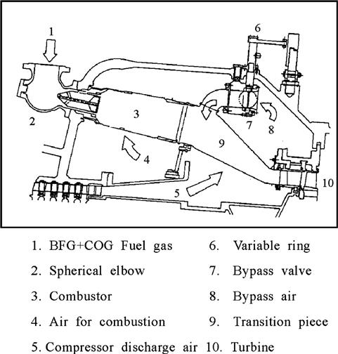
Several design improvements were introduced together with the multi-cannular combustor to achieve suitable combustion, as follows.
Bypass Valve
A bypass valve is equipped on the transition piece, as shown in Figure 4.73. This valve allows regulation of the airflow to the combustion area by adjusting the valve opening improving the combustion characteristic during the gas turbine part load operation. Combustion efficiency in excess of 99% can be achieved from ignition to full load as shown in Figure 4.74. A suitable combustion maintained at load rejection is also achieved by using the combustor by-pass valve.
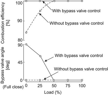
Flame Speed in Combustion Area
Combustion of low calorie gas exhibits lower burning velocity and lower adiabatic flame temperature. Therefore, longer residence time is needed in the combustion area to achieve flame stability and high combustion efficiency. Compared with combustors designed for natural gas, low calorie combustors are designed with larger cross-sectional area to achieve longer residence time. However, careful consideration of the combustor metal temperature is required. The bypass valve contributes to maintain stable combustion and avoid high metal temperatures in the combustor.
Configurations and Field Experience with Low Calorie Fuels
Depending on the amount of by-product gas available and the power generation needs, Mitsubishi applies one of three configurations:
This section describes features of each configuration and presents relevant operational data of examples of each configuration.
Small Gas Turbine Size (30 MW Class M251)
As shown in the table above, several small-size low calorie plants have been built in Japan with different class units including MW171, MW, 301, MF111, and M251. The M251 has become the standard Mitsubishi gas turbine for small-size applications.
M251 Series Gas Turbine Combustor with BFG and Pilot COG
An interesting application of an M251 gas turbine burning BFG with COG as pilot fuel started in commercial operation in 2006. This combination was implemented to meet the end-user required operation without fuel oil. Figure 4–75 shows the combustor configuration for this gas turbine. A COG pilot nozzle is implemented at the center of the BFG nozzle in order to maintain stable combustion with the low calorie BFG flame.
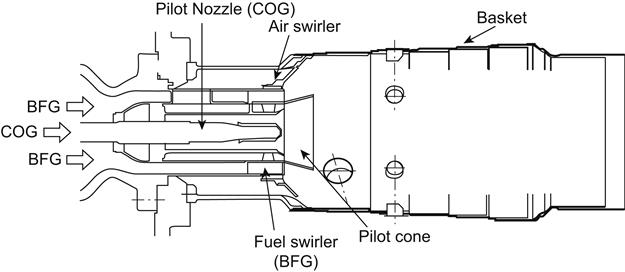
Mitsubishi has applied this type of combustor on five units within a BFG calorie range of 700 kcal/Nm3 ∼ 800 kcal/Nm3.
Field Experience
Special instrumentation was installed during the commissioning period in order to take measurements for confirming performance and reliability. The instrumentation included combustor and transition piece metal temperatures as well as combustor pressure fluctuations measurements. Data confirmed operation below the allowable levels. NOx levels at base load condition were confirmed to be lower than 25ppm (15%O2). CO also achieved low level throughout the entire load range.
Medium Gas Turbine Size (90 MW Class M501DA or M701DA)
M501DA and M701DA are being used for mid-size low calorie combined cycles. In the last three years, as many as eight units were booked, two of them recently commissioned and the rest are under manufacturing or commissioning.
M501DA Series Gas Combustor with FOG
A M501DA gas turbine burning a non-conventional by-product gas called Finex Oven Gas (FOG) started commercial operation this year. Figure 4.76 shows the configuration of the gas fuel nozzle, fuel-swirler, air-swirler and basket for this plant. In this application, the FOG is mixed with N2 or COG in order to control the fuel gas calorie. It can achieve suitable combustion from ignition to full load condition using only gas fuel.
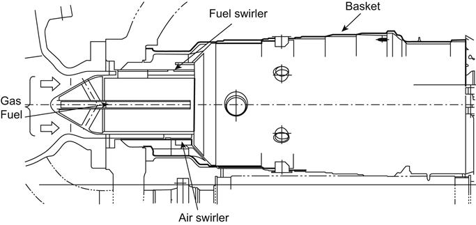
Field Experience
Combustor basket and transition piece metal temperature were measured throughout the entire load range. Both temperatures were confirmed within allowable levels. The combustor pressure fluctuations were confirmed to be lower than the allowable level. The emission levels were also monitored. Both NOx and CO levels were low and within the contractual limits.
Large Gas Turbine Size (180 MW Class M701F)
A high efficiency combined cycle based on the M701F gas turbine firing BFG with an inlet temperature exceeding 1300°C was developed and commissioned in 2004 for a Japanese steel factory (Figure 4–77). A similar plant was later built and commissioned in China.
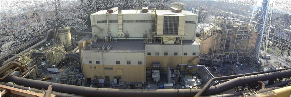
These combined cycle plants include impressive and unprecedented features:
• 50% (LHV base) plant thermal efficiency.
• A multi-can-annular combustor with air bypass valve to allow low caloric gas operation over the entire operating range (from turbine startup to full load operation).
• The gas turbine, generator, steam turbine, and gas compressor are coupled on a single 56 meter long shaft.
• An 87 MW gas compressor is connected to the single shaft arrangement through a step-up gear.
• In order to prevent mutual interference resulting from longitudinal thermal expansion of the shaft, both ends of the steam turbine shaft are fitted with flexible couplings.
• The plant is started up by the main steam turbine using steam from an existing boiler.
This eliminates the need for startup device.
• The multi-can-annular low NOx combustor with air bypass valve allows low NOx operation without steam or water injection.
• A gas decompression device with direct water cooling system, developed by Mitsubishi, is installed to enable recirculation of the high temperature and high-pressure gas
• discharged from the gas compressor outlet to the gas supply line in case of emergency
• A full automatic control system makes it possible for one or two operators to control and monitor the plant from a central control room.
Turbines10
The turbine has the task of providing the power to drive the compressor and accessories and, in the case of engines that do not make use solely of a jet for propulsion, of providing shaft power for a propeller or rotor. It does this by extracting energy from the hot gases released from the combustion system and expanding them to a lower pressure and temperature. High stresses are involved in this process, and for efficient operation, the turbine blade tips may rotate at speeds over 1500 ft per sec. The continuous flow of gas to which the turbine is exposed may have an entry temperature between 850 and 1700°C and may reach a velocity of over 2500 ft per sec in parts of the turbine.
To produce the driving torque, the turbine may consist of several stages each employing one row of stationary nozzle guide vanes and one row of moving blades (Figure 4–78). The number of stages depends upon the relationship between the power required from the gas flow, the rotational speed at which it must be produced, and the diameter of turbine permitted.
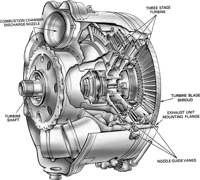
The number of shafts, and therefore turbines, varies with the type of engine; high compression ratio engines usually have two shafts, driving high and low-pressure compressors (Figure 4–79). On high bypass ratio fan engines that feature an intermediate pressure system, another turbine may be interposed between the high- and low-pressure turbines, thus forming a triple-spool system (Figure 4–80). On some engines, driving torque is derived from a free-power turbine (Figure 4–81). This method allows the turbine to run at its optimum speed because it is mechanically independent of other turbine and compressor shafts.
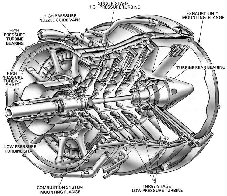
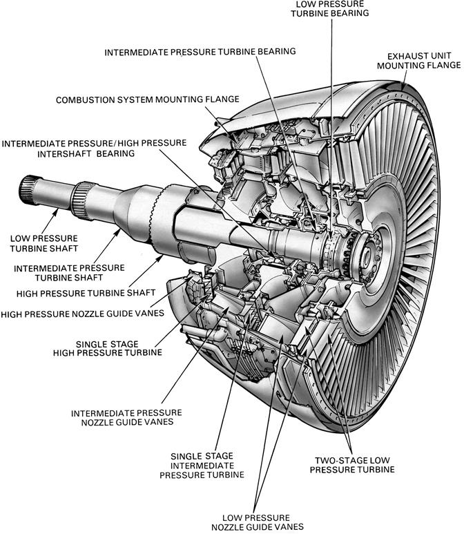
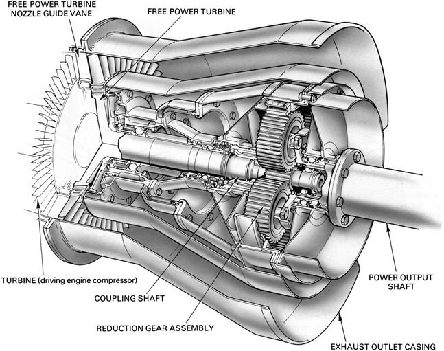
The mean blade speed of a turbine has considerable effect on the maximum efficiency possible for a given stage output. For a given output the gas velocities, deflections, and hence losses are reduced in proportion to the square of higher mean blade speeds. Stress in the turbine disc increases as the square of the speed, therefore to maintain the same stress level at higher speed, the sectional thickness, hence the weight, must be increased disproportionately. For this reason, the final design is a compromise between efficiency and weight. Engines operating at higher turbine inlet temperatures are thermally more efficient and have an improved power to weight ratio. By-pass engines have a better propulsive efficiency and thus can have a smaller turbine for a given thrust.
The design of the nozzle guide vane and turbine blade passages is based broadly on aerodynamic considerations, and to obtain optimum efficiency, compatible with compressor and combustion design, the nozzle guide vanes and turbine blades are of basic aerofoil shape. There are three types of turbine: impulse, reaction, and a combination of the two known as impulse/reaction. In the impulse type the total pressure drop across each stage occurs in the fixed nozzle guide vanes, which, because of their convergent shape, increase the gas velocity while reducing the pressure. The gas is directed onto the turbine blades which experience an impulse force caused by the impact of the gas on the blades. In the reaction type the fixed nozzle guide vanes are designed to alter the gas flow direction without changing the pressure. The converging blade passages experience a reaction force resulting from the expansion and acceleration of the gas. Normally gas turbine engines do not use pure impulse or pure reaction turbine blades but the impulse/reaction combination (Figure 4–82). The proportion of each principle incorporated in the design of a turbine is largely dependent on the type of engine in which the turbine is to operate, but in general it is about 50% impulse and 50% reaction. Impulse-type turbines are used for cartridge and air starters.
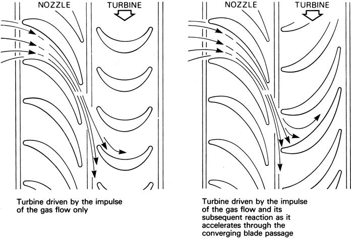
Energy Transfer from Gas Flow to Turbine
From the previous description, it will be seen that the turbine depends for its operation on the transfer of energy between the combustion gases and the turbine. This transfer is never 100% because of thermodynamic and mechanical losses.
When the gas is expanded by the combustion process, it forces its way into the discharge nozzles of the turbine, where, because of their convergent shape, it is accelerated to about the speed of sound, which, at the gas temperature, is about 2500 ft per sec. At the same time the gas flow is given a “spin” or “whirl” in the direction of rotation of the turbine blades by the nozzle guide vanes. On impact with the blades and during the subsequent reaction through the blades, energy is absorbed, causing the turbine to rotate at high speed and so provide the power for driving the turbine shaft and compressor.
The torque or turning power applied to the turbine is governed by the rate of gas flow and the energy change of the gas between the inlet and the outlet of the turbine blades. The design of the turbine is such that the whirl will be removed from the gas stream so that the flow at exit from the turbine will be substantially “straightened out” to give an axial flow into the exhaust system. Excessive residual whirl reduces the efficiency of the exhaust system and also tends to produce jet pipe vibration, which has a detrimental effect on the exhaust cone supports and struts.
It will be seen that the nozzle guide vanes and blades of the turbine are “twisted,” the blades having a stagger angle that is greater at the tip than at the root (Figure 4–83). The reason for the twist is to make the gas flow from the combustion system do equal work at all positions along the length of the blade and to ensure that the flow enters the exhaust system with a uniform axial velocity. This results in certain changes in velocity, pressure, and temperature occurring through the turbine, as shown diagrammatically in Figure 4–84.
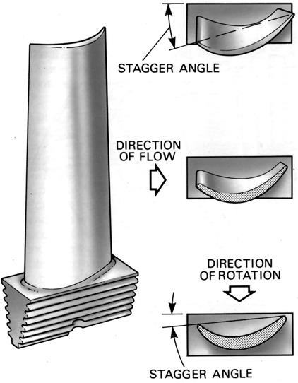
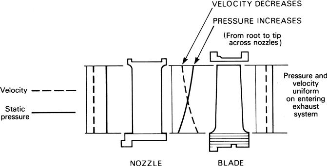
The “degree of reaction” varies from root to tip, being least at the root and highest at the tip, with the mean section having the chosen value of about 50%.
The losses that prevent the turbine from being 100% efficient are due to a number of reasons. A typical uncooled three-stage turbine would suffer a 3.5% loss because of aerodynamic losses in the turbine blades. A further 4.5% loss would be incurred by aerodynamic losses in the nozzle guide vanes, gas leakage over the turbine blade tips, and exhaust system losses; these losses are of approximately equal proportions. The total losses result in an overall efficiency of approximately 92%.
Construction
The basic components of the turbine are the combustion discharge nozzles, the nozzle guide vanes, the turbine discs, and the turbine blades. The rotating assembly is carried on bearings mounted in the turbine casing and the turbine shaft may be common to the compressor shaft or connected to it by a self-aligning coupling.
Nozzle Guide Vanes
The nozzle guide vanes are of an aerofoil shape with the passage between adjacent vanes forming a convergent duct. The vanes are located (Figure 4–85) in the turbine casing in a manner that allows for expansion.
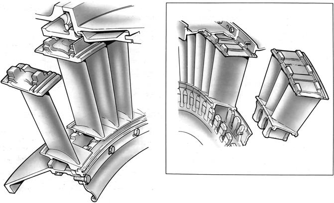
The nozzle guide vanes are usually of hollow form and may be cooled by passing compressor delivery air through them to reduce the effects of high thermal stresses and gas loads.
Turbine Discs
Turbine discs are usually manufactured from a machined forging with an integral shaft or with a flange onto which the shaft may be bolted. The disc also has, around its perimeter, provision for the attachment of the turbine blades.
To limit the effect of heat conduction from the turbine blades to the disc, a flow of cooling air is passed across both sides of each disc.
Turbine Blades
The turbine blades are of an aerofoil shape, designed to provide passages between adjacent blades that give a steady acceleration of the flow up to the “throat,” where the area is smallest and the velocity reaches that required at exit to produce the required degree of reaction.
The actual area of each blade cross-section is fixed by the permitted stress in the material used and by the size of any holes that may be required for cooling purposes. High efficiency demands thin trailing edges to the sections, but a compromise has to be made so as to prevent the blades cracking due to the temperature changes during engine operation.
The method of attaching the blades to the turbine disc is of considerable importance, since the stress in the disc around the fixing or in the blade root has an important bearing on the limiting rim speed. The blades on the early Whittle engine were attached by the de Laval bulb root fixing, but this design was soon superseded by the “fir-tree” fixing that is now used in the majority of gas turbine engines. This type of fixing involves very accurate machining to ensure that the loading is shared by all the serrations. The blade is free in the serrations when the turbine is stationary and is stiffened in the root by centrifugal loading when the turbine is rotating. Various methods of blade attachment are shown in Figure 4–86; however, the B.M.W. hollow blade and the de Laval bulb root types are not now generally used on gas turbine engines.

A gap exists between the blade tips and casing, which varies in size due to the different rates of expansion and contraction. To reduce the loss of efficiency through gas leakage across the blade tips, a shroud is often fitted as was shown in Figure 4–86. This is made up by a small segment at the tip of each blade, which forms a peripheral ring around the blade tips. An abradable lining in the casing may also be used to reduce gas leakage. Active clearance control (A.C.C.) is a more effective method of maintaining minimum tip clearance throughout the flight cycle. Air from the compressor is used to cool the turbine casing and, when used with shroudless turbine blades, enables higher temperatures and speeds to be used.
Contrarotating Turbine
Figure 4–87 shows a 12-stage contrarotating free-power turbine driving a contrarotating rear fan. This design has only one row of static nozzle guide vanes. The remaining nozzle guide vanes are, in effect, turbine blades attached to a rotating casing, which revolves in the opposite direction to a rotating drum. Since all but one aerofoil row extracts energy from the gas stream, contrarotating turbines are capable of operating at much higher stage loadings than conventional turbines, making them attractive for direct drive applications.
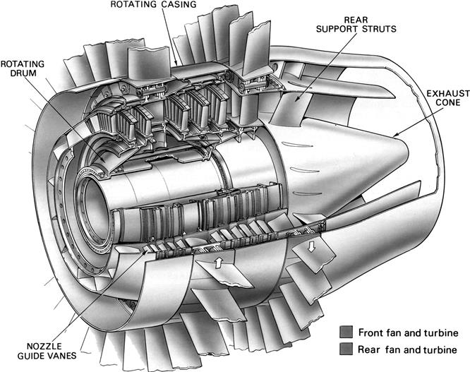
Dual-Alloy Discs
Very high stresses are imposed on the blade root fixing of high work rate turbines, which make conventional methods of blade attachment impractical. A dual alloy disc, or “blisk,” as shown in Figure 4–88, has a ring of cast turbine blades bonded to the disc. This type of turbine is suitable for small high-power helicopter engines.
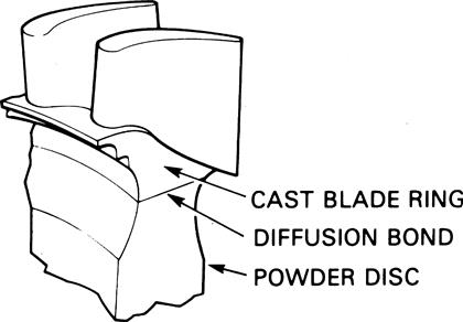
Compressor–Turbine Matching
The flow characteristics of the turbine must be very carefully matched with those of the compressor to obtain the maximum efficiency and performance of the engine. If, for example, the nozzle guide vanes allowed too low a maximum flow, then a back pressure would build up causing the compressor to surge; too high a flow would cause the compressor to choke. In either condition a loss of efficiency would very rapidly occur.
Materials
Among the obstacles in the way of using higher turbine entry temperatures have always been the effects of these temperatures on the nozzle guide vanes and turbine blades. The high speed of rotation, which imparts tensile stress to the turbine disc and blades, is also a limiting factor.
Nozzle Guide Vanes
Due to their static condition, the nozzle guide vanes do not endure the same rotational stresses as the turbine blades. Therefore, heat resistance is the property most required. Nickel alloys are used, although cooling is required to prevent melting. Ceramic coatings can enhance the heat resisting properties and, for the same set of conditions, reduce the amount of cooling air required, thus improving engine efficiency.
Turbine Discs
A turbine disc has to rotate at high speed in a relatively cool environment and is subjected to large rotational stresses. The limiting factor that affects the useful disc life is its resistance to fatigue cracking.
In the past, turbine discs have been made in ferritic and austenitic steels but nickel-based alloys are currently used. Increasing the alloying elements in nickel extends the life limits of a disc by increasing fatigue resistance. Alternatively, expensive powder metallurgy discs, which offer an additional 10% in strength, allow faster rotational speeds to be achieved.
Turbine Blades
A brief mention of some of the points to be considered in connection with turbine blade design will give an idea of the importance of the correct choice of blade material. The blades, while glowing red-hot, must be strong enough to carry the centrifugal loads due to rotation at high speed. A small turbine blade weighing only 2 ounces may exert a load of over 2 tons at top speed and it must withstand the high bending loads applied by the gas to produce the many thousands of turbine horsepower necessary to drive the compressor. Turbine blades must also be resistant to fatigue and thermal shock, so that they will not fail under the influence of high frequency fluctuations in the gas conditions, and they must also be resistant to corrosion and oxidization. In spite of all these demands, the blades must be made in a material that can be accurately formed and machined by current manufacturing methods.
From the foregoing, it follows that for a particular blade material and an acceptable safe life there is an associated maximum permissible turbine entry temperature and a corresponding maximum engine power. It is not surprising, therefore, that metallurgists and designers are constantly searching for better turbine blade materials and improved methods of blade cooling.
Over a period of operational time the turbine blades slowly grow in length. This phenomenon is known as “creep” and there is a finite useful life limit before failure occurs.
The early materials used were high temperature steel forgings, but these were rapidly replaced by cast nickel base alloys that give better creep and fatigue properties.
Close examination of a conventional turbine blade reveals a myriad of crystals that lie in all directions (equiaxed). Improved service life can be obtained by aligning the crystals to form columns along the blade length, produced by a method known as “directional solidification.” A further advance of this technique is to make the blade out of a single crystal. Examples of these structures are shown in Figure 4–89. Each method extends the useful creep life of the blade (Figure 4–90) and in the case of the single crystal blade, the operating temperature can be substantially increased.
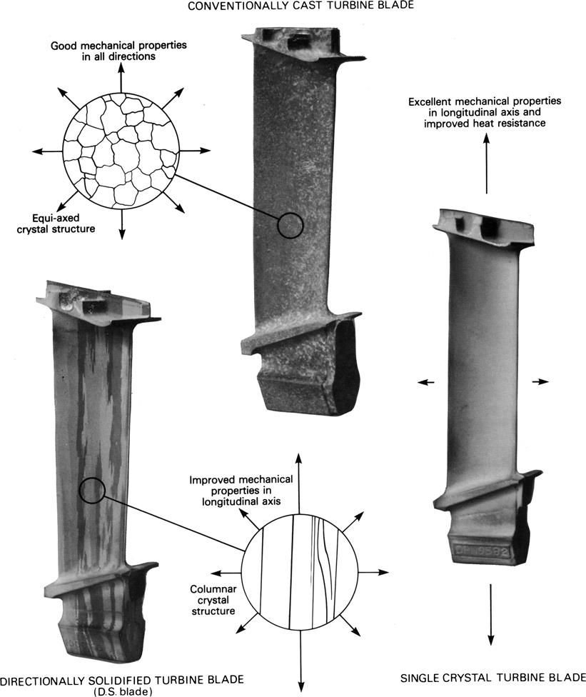
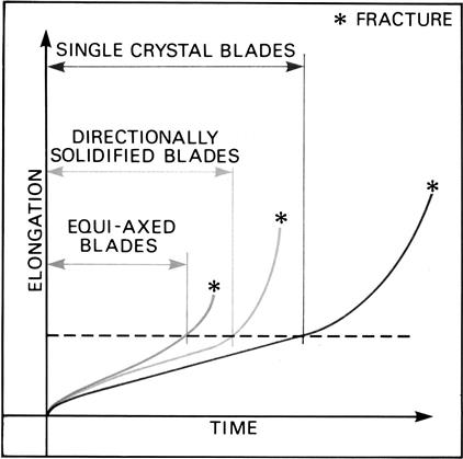
A non-metal-based turbine blade can be manufactured from reinforced ceramics. Their initial production application is likely to be for small high-speed turbines that have very high turbine entry temperatures. An example of a ceramic blade is shown in Figure 4–91.
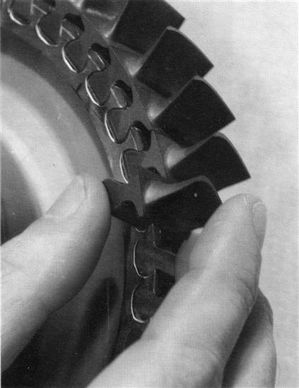
The following three cases11 illustrate some of the issues involved in uprating the power and temperature ceilings of a gas turbine. The cases are drawn from Mitsubishi’s work on “J” and “H” technology development. As with other cases in this book, the reader is asked to note the year of publication for the H technology paper is 2001 and for the J papers is 2012. This serves to illustrate how involved design development is, even when based on a similar core design. I have left in the earlier paper as it helps illustrate the careful increments with which OEMs must proceed when enlarging their core design.
Certain details, such as actual load testing, will be significant to endusers who have had issues with gas turbines that have not had benefit of load test at the OEM’s facility. It is appropriate when buying a new turbine package or even a fleet of them to consider load testing, particularly full load testing, as one of the primary turbine selection factors when comparing OEMs.
In Mitsubishi’s case, their work was being supported by a Japanese national grant. The overall objective was to attain a TIT of 1600 degrees Celsius and raise efficiency for the GT CC package by 5–6% thus taking it past the 60% efficiency point to 62% and higher.
Case Study 5: Development of a 60cps “J” Technology Turbine12
High-efficiency, natural gas-fired combined cycles generate considerably lower CO2 emissions, especially compared with conventional power generation based on coal or liquid hydrocarbons.
Since 2004, MHI started participation in a Japanese government-funded project called the Japanese National Project. This project is still ongoing and targets combined cycle efficiencies in the 62 to 65% range through the development of innovative technology. The gas turbine for this National Project is expected to operate at a Turbine Inlet Temperature of 1700°C. The first phase of this project was completed in 2007 and involved considerable R&D efforts. It steered the following developments:
• Enhanced turbine aerodynamics
• Higher turbine cooling efficiency
• Advanced thermal barrier coating
• Higher pressure ratio compressor
The M501J operates at an intermediate TIT between the 1700°C goal of the Japanese National Project and the current 1500°C technology. This approach allows early application of the technology developed for the 1700°C TIT class gas turbine and provides initial validation of the technology at a lower temperature exposure.
Features of the M501J/M701J
Several component technologies developed for the National Project were used to design the J series (refer to Figure 4–92). High-performance cooling schemes with reduced-cooling air requirements and new thermal barrier coating materials facilitated the increase of TIT to the record-breaking 1600°C, while maintaining the turbine reliability and operating life.
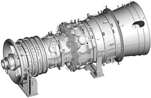
The new thermal barrier coating materials provided substantial reduction in thermal conductivity compared with conventional YSZ type without compromising durability.
By combining a 1600°C TIT and a pressure ratio of 23:1, the J-series gas turbine provides large power generation capacity and high thermal efficiency, as shown in Table 4–3. These parameters were revised upward based on better-than-expected performance during the validation period.
The Economy of Large Frame Gas Turbine Validation
The design and testing of new gas turbines is expensive and time-consuming. During the initial development stage, there are large R&D expenditures associated with the design and individual component testing. This effort is typically followed by shop tests where the new engine is carefully monitored through numerous temporary sensors. These tests typically begin with turning operation and are followed by first ignition, no load operation, first synchronizing, and operation at different loads. Shop tests are typically run off-grid and the maximum load and duration will depend on the capacity of the hydraulic brakes or other energy dissipating devices, as well as the validation budgets to cover the spent fuel.
A study conducted by EPRI determined that fuel costs constitute 68% of a large-frame combined cycle plant’s total cash flow (net present value basis). The power generated off-grid does not provide any revenue and cannot be economically sustained for extended periods of time.
Testing while connected to the grid imposes a rotating speed that is dictated by the grid frequency. However, if the power generated is sold, it allows sustained validation for extended time. Testing a prototype off the grid allows adjustments of the operating speed to confirm “under” and “over” frequency characteristics of the new engine, as well as compressor surge margins.
MHI’s gas turbine manufacturing facility in Japan has the energy dissipation capabilities (water break) required to perform off-grid testing. However, the final long-term “load dynamic” validation takes place at the demonstration plant on the premises of Takasago Machinery Works (Figure 4–93). This approach expedites the maturity process while avoiding clients’ exposure to prototype units.
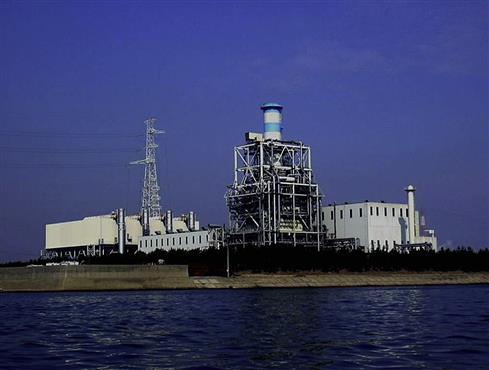
Status of M501J Validation
T-Point Power Station started commercial operation in 1997. Prior to the installation of the M501J gas turbine this plant facilitated the deployment of the M501G gas turbine, which became the largest steam-cooled fleet of gas turbines in the market. Different upgrades of the G series were validated in the plant accumulating close to 40,000 actual hours and more than 2100 starts. T-Point operating hours, as well as the loading profiles, are determined by Kansai Electric who purchases the output from MHI. The pie chart in Figure 4–94 shows the historical distribution of operating modes (78% daily start/stop or DSS, 7% weekly start/stops or WSS, and 15% continuous operation).
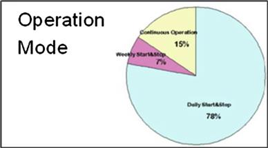
The T-Point service factor has been increased after the March 11, 2011 earthquake and tsunami to alleviate the power shortage. Figure 4–95 shows the GWh generated since that tragic event.
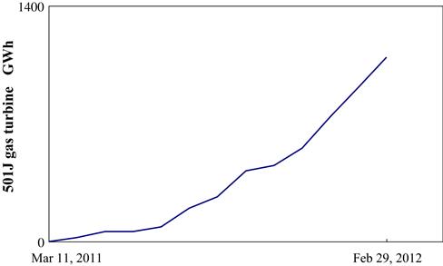
Figure 4–96 shows the first M501J in transit from Takasago Machinery Works’ assembly building to T-Point, where it was installed in November 2010. The first fire took place in February 2011 and the record-breaking 1600°C TIT was reached on February 23, 2011.
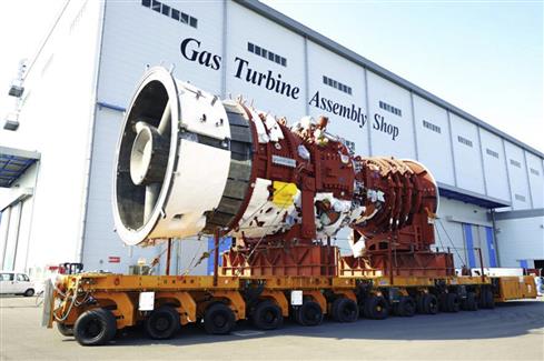
Figures 4–97 to 4–100 show measurement results recorded during the commissioning period with all parameters well below the allowable limits.
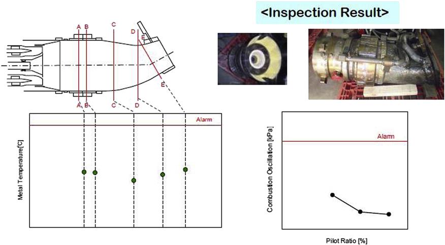
Figure 4–97 includes transition piece metal temperature data as well as combustion dynamics measured under 1600°C operation. It also shows the condition of the hardware during the removal of temporary instrumentation.
Figure 4–98 shows the Turbine Row 1 Vane metal temperature measured during 1600°C operation. Turbine Row 1 Blade surface temperature was also measured by the use of pyrometer and the results are shown in Figure 4–99.
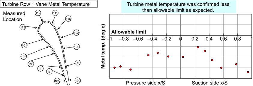
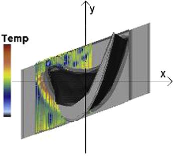
The M501J applies the same Active Clearance Control technology successfully used in the G Fleet, with demonstrated improvement of efficiency under load operating conditions. Figure 4–100 shows the measured clearance for Turbine Row 2 Blade.
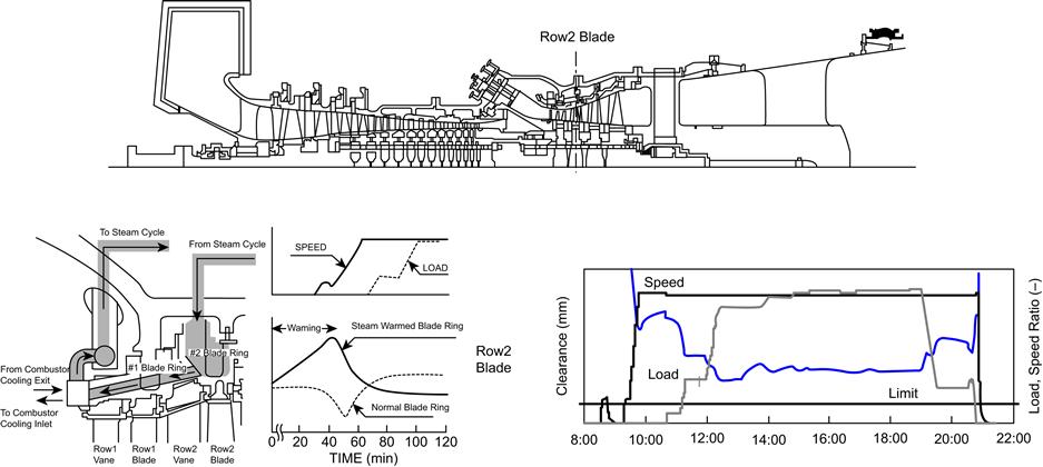
At the end of the initial trial run, the unit was inspected and all parts were found in good condition.
The commissioning period of this unit was completed in June 2011 and commercial operation run started in July. At the time of submitting this article, the unit had accumulated more than 5300 actual operating hours and 62 starts.
With a combined cycle efficiency of 61.5%, the J-series GTCC power generation will considerably reduce the CO2 emissions released by the existing technology and therefore will contribute to reducing global warming.
Case Study 6: Development and Operation Experience of Mitsubishi 50 Hz Large-Frame (M701F) Gas Turbines13
This case illustrates how successive models of gas turbine build on the previous update. Similar to the J Series, the M701F5 targets increased combined cycle efficiency and the associated reduction in fuel consumption and CO2 emissions.
M701F4 Features and Fleet Update
The M701F4 is the upgraded version of the M701F3 which was developed in 1999. It incorporates a 6% increase of the compressor inlet flow to raise the power output. It also includes an advanced air-cooled combustor with 50°F higher firing temperature (compared with the preceding M701F3). The cooling technology applied to this machine and the last stage turbine blades were retrofitted from the G series gas turbines (refer to Figure 4–101). It further illustrates how adjustments can be made to the gas turbine’s basic systems to accommodate shortage of resources (such as cooling water) to adjust for disasters such as Japan’s Sendai earthquake in 2011. Reminder: the Japanese power grid operates both 50 and 60 cps systems.
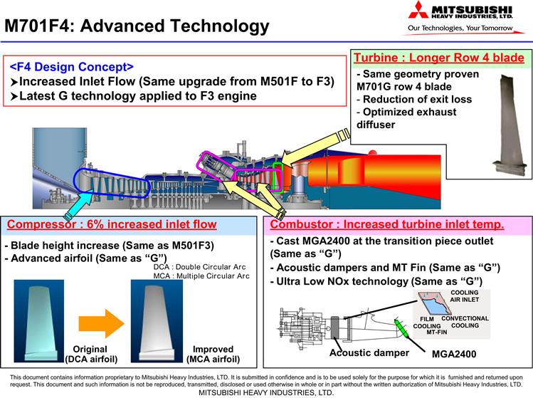
The first M701F4 unit went commercial in July 2010 at the Sendai combined cycle Power Station in Japan (refer to Figure 4–102). The construction of this plant was handled as a turnkey project by MHI and the commissioning proceeded as scheduled. This is a single-shaft plant with a generation capacity of 446 MW. It features a Mitsubishi tandem compound double-flow TC2F-40.5 ISB steam turbine with 40.5-inch last stage blades (refer to Figure 4–103). This plant operated as the fleet leader unit until it was temporarily taken out of production by the Sendai earthquake and tsunami. Until then, it had been operated on a daily start/stop (DSS) approach accumulating 4643 Actual Operating Hours (AOH) and 166 starts without any trips.
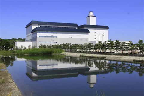
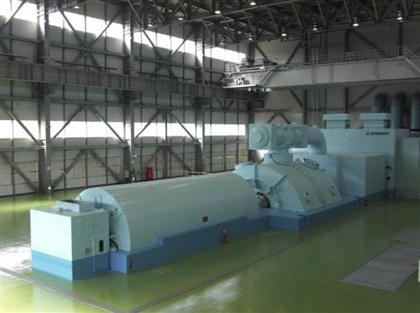
The plant was restored and brought back into operation in early 2012, increasing the number of hours to 6200 and 175 starts.
Another 2 on 1 combined cycle plant was built in Turkey and started commercial operation in December 2010 (refer to Figure 4–104). The plant is rated 919 MW, powered by two M701F4 gas turbines and a tandem compound four-flow steam turbine with 40.5-inch last row blades (Mitsubishi TC4F-40.5 ISB). It achieved a net efficiency level of more than 59%, less than 15 ppm of NOx and 10 ppm of CO emissions.
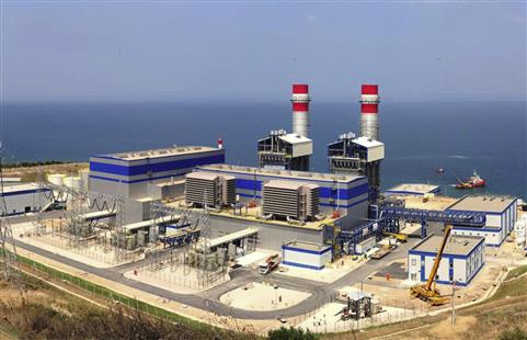
These units surpassed the Sendai unit and became fleet leaders with the #11GT accumulating 10,059 AOH with 112 starts, while the #12GT accumulated 9591 AOH with 115 starts.
Temporary Measurements of the First M701F4
A comprehensive set of temporary measurements was used during the commissioning of the first M701F4 to confirm its performance and reliability. More than 500 sensors were mounted on the gas turbine (refer to Figure 4–105). All measurement points displayed values within expected levels. Figure 4–106 shows the metal temperature measured on the Turbine Row 1 Vane.
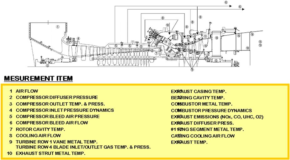
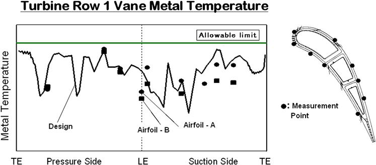
Source of New Technology
MHI has been engaged in a Japanese government-funded project called the “National Project” since 2004. The main target of this project is the development of a 1700°C (3092°F) class gas turbine in order to achieve 62–65% (LHV) combined cycle efficiency. This represents a 5–10% increase compared with the current available technology.
Several technological improvements derived from the first stage of the National Project include:
• Exhaust Gas Recirculation (EGR) combustor
• Lower thermal conductivity TBC
• Higher loading turbine aerodynamics
Mitsubishi has retrofitted several of the developed technologies into existing as well as new gas turbine developments.
Conversion of Steam-Cooled 50 Hz G Units into GAC
The Japanese power grid has experienced severe shortages after the 2011 earthquake and tsunami. Motivated to alleviate the situation, Tokyo Electric and MHI engaged in a quick installation of three 50 Hz steam-cooled engines that were stored at Takasago Machinery Works for a delayed project. In order to quickly bring these units into simple cycle operation, they were converted to air-cooled units by replacing the steam-cooled liners with air-cooled hardware.
Two of the three M701GAC units were brought into commercial operation by the summer of 2011 (refer to Figure 4–107), barely 5–6 months after the earthquake, helping alleviate the difficult power crises caused by the earthquake and tsunami.
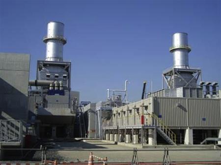
Development of the M701J Gas Turbine
Several articles listed in the reference section present a description of the 60 Hz M501J. The first engine of this revolutionary technology has been in commercial operation since June 2011 and has accumulated more than 5300 AOH and 62 starts.
MHI has already delivered the first of six M501J gas turbines to Kansai Electric Power Company (KEPCO) in Japan. The six-unit single-shaft combined cycle plant called Himeji is being built by MHI on a turn-key basis with the first unit scheduled to go commercial by 2014. Ten additional units will follow in Korea.
The 50 Hz counterpart was designed as a scaled-up version of the M501J. It will operate at the same turbine inlet temperature (TIT) of 1600°C and pressure ratio of 23:1 to achieve a combined cycle thermal efficiency of 61.7%.
This engine was designed based on the proven steam cooling approach developed and extensively used in the G series, while incorporating state-of-the-art technologies developed by Japanese National Project. The incorporated technologies include advanced turbine cooling, improved turbine aerodynamics, and advanced TBC.
The resulting higher exhaust gas temperature will be effectively used in combined cycle application (refer to Figure 4–108).
Figure 4–109 shows the evolution of TIT and its effect on efficiency and power output. The J-series combined cycle is expected to achieve over 61% efficiency (LHV), while its power generation capacity will be about 20% higher than that of the G-series.
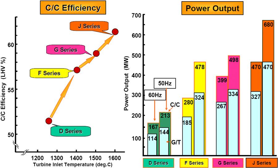
Table 4–3 shows the J-series gas turbine rated power output for 60 Hz and 50 Hz in 1:1 single-shaft combined cycle configuration.
The first unit of the M701J is scheduled to start commercial operation in 2016.
Development of the M701F5 Gas Turbine (50 Hz)
By applying the state-of-the-art technologies developed for the J and the air-cooled GAC engines (M501GAC, M701GAC), MHI is developing the M701F5 gas turbine, which is the upgraded version of the proven M701F4 (refer to Figure 4–110).
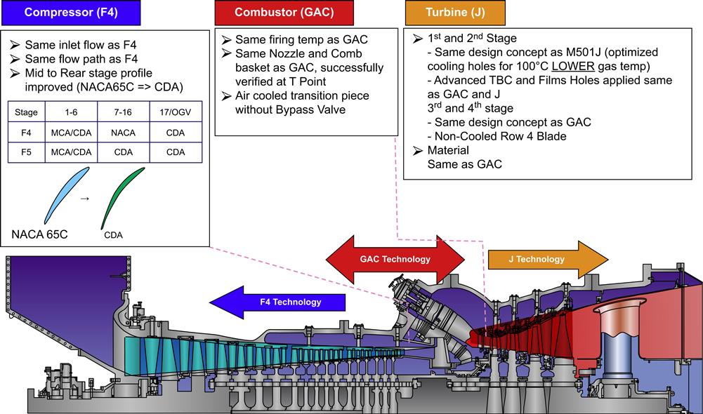
The M701F5 consists of the same F4 compressor, air-cooled combustors with TIT of 1500°C proven by GAC engines and the J turbine components. The M701F5 gas turbine is expected to maintain high reliability based on the use of proven components. A 1:1 combined cycle with the M701F5 will generate the power output of 525 MW with an efficiency of 61% (refer to Figure 4.111).
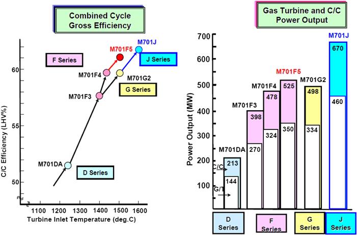
Case Study 7: Development of an “H” Technology Turbine14
Mitsubishi Heavy Industries Ltd. (MHI) developed the M501H gas turbine to improve the efficiency and power of the G series using closed steam cooling of stage 1 and 2 blades and vanes following the firm’s experience in the construction of the D, F, and G series. Development included elementary tests for preverification and trial operation using a combined plant verification plant to reach 220 MW in May 1999 and to verify the stability of the steam cooling rotor, cooling properties of blades and vanes, and the efficiency of major components.
Mitsubishi Heavy Industries Ltd. developed the 1150°C class large capacity gas turbine, M701D, in 1981 and subsequently verified its high plant total thermal efficiency, high reliability, and low pollution at Tohoku Electric Power Co. Inc., Higashi Niigata Thermal Power Plant #3 Power Train. In 1985, MHI started development of the 1350°C class “F” series gas turbine (M501F/M701F), and an actual loading shop test was conducted on the initial unit in 1989. MHI has already received orders for 90 “F” series gas turbines as the main engines for combined cycle power plants in both domestic and overseas locations, and 41 out of 90 units have been accumulating experience with successful operation.
MHI started development of the 1500°C class “G” series gas turbine (M501G/M701G) in 1993. A trial operation of the M501G gas turbine for the 60 Hz market started in February 1997 at the Takasago in-house verification plant for combined cycle power plant (“T”-Point), and a verification operation started in June 1997 as a long-term reliability verification unit. On the other hand, the M701G1 gas turbine for 50 Hz market was started with a trial operation at Tohoku Electric Power Co. Inc., Higashi Niigata Thermal Power Plant #4 Power Train on October 15, 1998, and was put into commercial operation in July 1999. Currently, MHI has received orders for 45 “G” series gas turbines, and three out of 45 units are now being successfully operated. Based on abundant experience of electric utility gas turbines such as the “D,” “F,” and “G” series, MHI developed the “H” series gas turbine. The “H” series is a 1500°C class gas turbine, which is the same as the “G” series gas turbine; however, the “D,” “F,” and “G” series gas turbines adopted air cooling for turbine blades and vanes, while the “H” series gas turbine adopted steam cooling, which is a main feature of this type of gas turbine. Thanks to steam cooling, high plant total thermal efficiency could be obtained.
This section describes the results of trial operation of the M501H gas turbine for the 60 Hz market at “T”-Point conducted in May 1999 in addition to the features of 1500°C class “H” series gas turbine.
Features of the “H” Series Gas Turbine
The “H” series gas turbine is a high performance gas turbine with 1500°C turbine inlet temperature. Compared with the existing gas turbines, the “H” series gas turbine is higher in plant total thermal efficiency by approximately 2% (absolute value), and larger in output by approximately 20%.
Overall Structure
The basic structure of the “H” series gas turbine is modeled after the “F” and “G” series gas turbines and inherits their proven technologies as follows:
• For the rotor, the two bearing support is adopted, with the support from both the compressor side bearing and turbine side bearing.
1. For the connection with the generator shaft, the compressor shaft end drive system, of which the amount of thermal effect such as thermal expansion is small and the flexible coupling is not required, is adopted.
2. The exhaust system is an axial flow exhaust structure, which is optimum for the layout of a combined cycle power plant.
3. As for the bearing support structure, the compressor side bearing is supported by eight radial struts, and the turbine side bearing is supported by tangential struts, which can easily absorb differential thermal expansion by keeping the shaft at the center.
• For the connecting structure, discs with torque pins are connected with bolts on the compressor rotor side, while discs with curvic couplings are connected with bolts on the turbine rotor side. Both of them have a structure of delivering torque without fail.
Steam Cooling Structure of Blades and Vanes
The “H” series gas turbine has a main feature that the rows 1 and 2 blades and vanes are cooled with steam being generated at the bottoming, while the existing ones are cooled with compressed high-pressure air discharged from the compressor.
Thanks to the application of a steam cooling system, the amount of cooling air can be reduced to approximately one half of the existing one, the mixture loss of cooling air can be also reduced, and the plant total thermal efficiency can be improved. In addition, combustion gas flow increases by the amount of reduced cooling air, and efficiency at the turbine section is increased, so these factors can improve the output.
Furthermore, the exhaust gas temperature increases by the reduced amount of low-temperature cooling air mixing with combustion gas at the same pressure ratio. So, the exhaust gas temperature keeps the existing level by increasing pressure ratio. For the compressor, the latest type blades and vanes were applied, and a high efficiency compressor having higher pressure ratio and reduced number of stages was developed. This compressor was adopted based on thorough verification using a 0.29 scale compressor.
Development of the “H” Series Gas Turbine
As shown in the Table 4–4, development of the “H” series gas turbine was started in 1996, and a trial operation was started in February 1999. The development for such a short period was supported by reliable verification through various component tests conducted abreast. The improvement required was reflected in the design in detail without losing an opportunity.
TABLE 4–4
Development of the “H” series Gas Turbine
| 1996 | 1997 | 1998 | 1999 | |
| T-Point M501H |
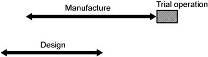 | |||
| Component Test |
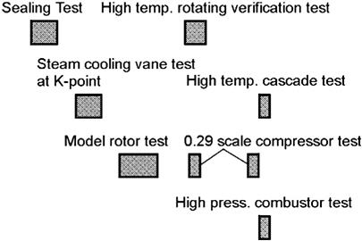 | |||
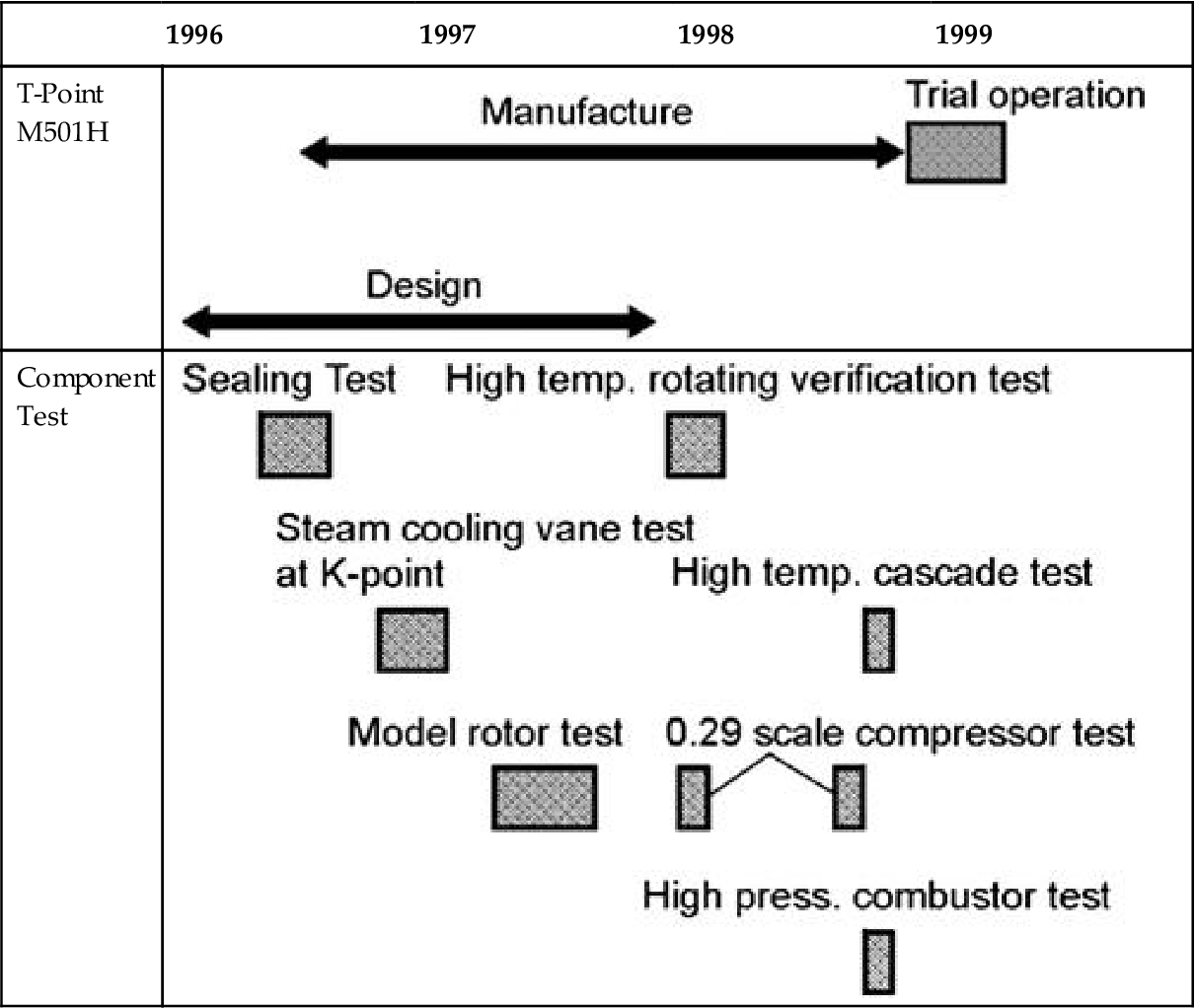
(Source: MHI.)
Confirmation Test of Steam-Sealing Characteristics
For the connections at the supply and recovery passage to/from steam cooled blades and vanes, a special seal which had not been used for the existing gas turbines was adopted. The “H” series gas turbine applies steam for cooling; however, if the same amount of leakage as the existing cooling air is allowed, a large amount of steam leakage will occur. Steam leakage reduces the plant total thermal efficiency and causes the increase of makeup water at the bottoming. Therefore, this seal is of critical importance.
In order to solve these issues in advance, sealing ability of the selected seal structure was confirmed through various component tests. First of all, a component test for checking sealing ability under the stationary condition was conducted on the components installed in both stationary system and rotating system to select optimum structure and dimension. Second, the components selected for rotating system were tested using the model rotor, which could simulate an actual rotating condition in order to check that sealing ability could be kept as designed.
Confirmation Test of Steam-Cooled Blades and Vanes
Several pieces of turbine row 1 vanes of the M701F gas turbine unit installed at MHI Yokohama Machinery Works (“K”-Point) were modified to steam cooled vanes. These modified vanes were cooled with steam under actual operation, and the expected data of cooling characteristics were obtained.
Prior to a trial operation of the “H” series gas turbine, a high temperature cascade test simulating the actual engine was conducted using the actual turbine row 1 blades cooled with steam as a medium of cooling. Through the test, the data of cooling characteristics were obtained in advance.
Confirmation Test of Compressor
A 0.29 scale compressor was manufactured for the “H” series gas turbine. This compressor was driven by a two-shaft gas turbine of M252 and equipped with a control valve for increasing pressure at the outlet.
Under such a condition, a model compressor test was conducted simulating various operating conditions. This compressor was confirmed to have the same level characteristics and performance as design from the data each of various starting up characteristics and compressor performance which could be obtained by changing pressure and rotating speed freely.
A high-pressure combustion test was conducted using the above-mentioned compressor, of which a high-pressure combustion test rig was equipped on the downstream side. A high-temperature rotation verification test was also performed.
This test rig is equipped with a combustor to which high-pressure air is supplied from the above-mentioned compressor, and natural gas is also supplied from a pipe line for combustion. A 1500°C combustion gas through the combustor is introduced to a 0.6 scale single-stage turbine for rotation. The rotating load is controlled by absorbing with a dynamometer to keep the rotating speed constant at 6000 rpm.
For development of the “H” series gas turbine, six blades of a scale design of “G” series gas turbine were modified to the steam cooling structure, and the steam passage was made on the bladed rotor for manufacturing a new type of gas turbine having the structure which can supply and recover steam from the shaft end.
As in the “H” series gas turbine, this gas turbine was operated under the condition where steam was supplied to the rotor from the shaft end for cooling steam cooled blades and then recovered from the shaft end through the rotor again. During operation, data from each of the cooling characteristics of blades, temperature, and vibration at each portion were obtained and confirmed to be at the same level as designed.
Results of “H” Series Gas Turbine Trial Operation
Outline of Trial Operation
A trial operation of the M501H gas turbine was conducted using the in-house combined cycle verification plant of MHI Takasago Machinery Works. Generally, this in-house verification plant is used for verifying long-term reliability of the M501G gas turbine; however, this plant was tentatively replaced with the M501H gas turbine for a trial operation. As shown in Figure 4–112, high-pressure steam generated at the exhaust heat recovery steam generator was introduced to the high-pressure steam turbine from which outlet steam was introduced to the steam cooled blades and vanes for cooling. The steam after cooling was recovered to the inlet of the middle pressure steam turbine.
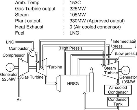
Results of Trial Operation
The trial operation was started on February 8, 1999, and 220 MW (GT output: 60 MW, ST output: 60 MW) output was achieved through various confirmations of actuation. From this trial operation, the first step targeting the verification of high-pressure compressor characteristics and steam system (cooling characteristics of steam cooled blades) was successfully completed. On the next step, the operation up to 1500°C will be planned to be carried out (Figure 4–113).
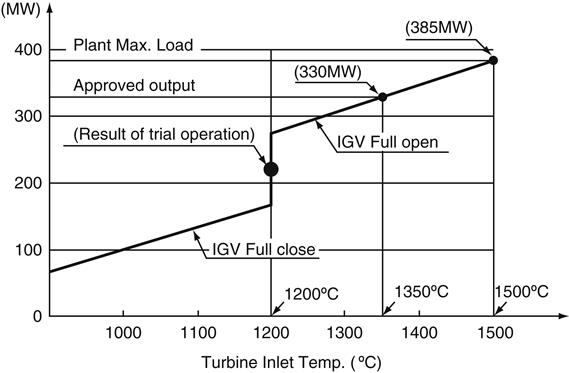
From the measurement results, it could be confirmed that cooling steam flowed through the turbine rotor, blades, blade rings, and vanes and proved effective cooling performance as designed. In addition, the condition after various tests was good.
Effects of Trial Operation
In this trial operation, a special measurement was carried out at 1500 points. The effects of this trial operation are shown below.
Confirmation Test of Steam-Sealing Characteristics
Steam is supplied from the rotor shaft end to the steam cooled blades through the inside of the rotor and recovered to the rotor shaft end through inside of the rotor again.
As shown in Figure 4–114, stable vibration characteristics were obtained in this trial operation. This trial operation was the first run for the “H” series gas turbine, so the operation was manually done as a general rule so that timely actions could be taken for various operating conditions.
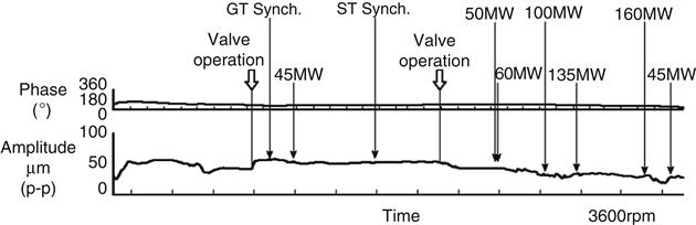
As mentioned previously, the characteristics of steam cooled blades and vanes had been confirmed in advance. In the results of the trial operation, expected cooling performance could be obtained. The output and the turbine inlet temperature were up to 220 MW and 1200°C in this trial operation; however, it was verified that the metal temperature was within the allowable limit by extrapolating the measurement data theoretically into the condition of 385 MW/T, 1500°C.
Confirmation of Performance of Compressor and Turbine
For the compressor, the data from each of the starting up characteristics and compressor performance were obtained in advance by a performance test using a 0.29 scale compressor as mentioned previously. In the results of the trial operation, the characteristics were quite similar to those obtained from the performance test. Therefore, starting up characteristics and compressor adiabatic efficiency were confirmed to be the same as designed.
Turbine aerodynamic efficiency was confirmed to have achieved the design efficiency from calculation with correction of steam leakage. The plant total thermal efficiency was confirmed to almost satisfy the design value.
In summary, the “H” series gas turbine adopted a steam cooling system from the bottoming for turbine blades and vanes, which had not been applied to the existing gas turbines. Thanks to the steam cooling system, the plant total thermal efficiency and output are both improved compared with other gas turbines of the same scale.
The above-mentioned new development elements have been verified by various component tests in advance. The basic structure inherited those of the existing gas turbines with high reliability. From the start of development, the trial operation was carried out in a short period, only 30 months, and the first step of operation was successfully completed with 220 MW output achieved.
In this trial operation, confirmation of each of stable operation of steam-cooled rotor, cooling characteristics of steam-cooled blades and vanes, and performance of compressor and turbine was successfully finished.
As shown above, this trial operation could verify that the “H” series gas turbine could achieve higher plant total thermal efficiency than the existing gas turbines.
This type of combined cycle power plant with LNG firing such as the “H” series gas turbine is now the focus of the world’s attention as a trump card for the countermeasure of global warmth because of its low CO2 emission, and it is quickly gaining in popularity in European and American countries.
In the domestic and Asian countries, spread of such a type of gas turbine is slow due to reduced growth of power demand caused by the global business recession; however, it will spread steadily accompanied by recovery of the business situation.