
Accessory Systems
Abstract
Accessory systems in a gas turbine is every system that occurs outside of or in addition to the bare gas turbine hardware. It also includes systems such as inlet air fogging systems, steam injection (for cooling or power augmentation) systems, and life cycle assessment systems. Systems such as one for online compressor washing would also be an accessory system; however, it is usually supplied with the gas turbine system when it is new. In some cases, certain cases on items such as steam injection to extend component lives or the TBO of the gas turbine. This chapter is devoted primarily to accessory systems that are essential to the gas turbine basic system and will always be supplied with it at initial purchase stage.
Keywords
Accessory systems; ignition systems; accessory drives; fire protection systems; water injection systems
“The shortest and surest way to live with honor in this world is to be in reality what we would appear to be.”
—Socrates
Accessory systems in a gas turbine is every system that occurs outside of or additional to, the bare gas turbine hardware. In other words, in additional to everything listed in the table of contents for this chapter, it would also include systems such as inlet air fogging systems, steam injection (for cooling or power augmentation) systems, life cycle assessment systems. The latter systems are commonly retrofitted on gas turbines for optimal performance.
Systems such as one for online compressor washing would also be an accessory system; however, it is usually supplied with the gas turbine system when it is new. Commonly, it is made by another smaller OEM, although the GT OEM may have his nameplate on it. Compressor washing is considered in the chapter on performance optimization (Chapter 10), as are the previously mentioned performance enhancement systems. In some cases, certain cases on items such as steam injection to extend component lives or the TBO of the gas turbine appear in Chapter 12 on Maintenance, Repair and Overhaul.
This chapter is devoted primarily to accessory systems that are essential to the gas turbine basic system and will always be supplied with it, at initial purchase stage.
Accessory Drives1
Accessory drive units provide the power for hydraulic, pneumatic, and electrical systems in addition to providing various pumps and control systems for efficient engine operation. The high level of dependence upon these units requires an extremely reliable drive system.
The drive for the accessory units is typically taken from a rotating engine shaft, via an internal gearbox, to an external gearbox that provides a mount for the accessories and distributes the appropriate geared drive to each accessory unit. A starter may also be fitted to provide an input torque to the engine. An accessory drive system on a high by-pass engine takes between 400 and 500 horsepower from the engine.
Gearboxes and Drives
Internal Gearbox
The location of the internal gearbox within the core of an engine is dictated by the difficulties of bringing the driveshaft radially outwards and the space available within the engine core.
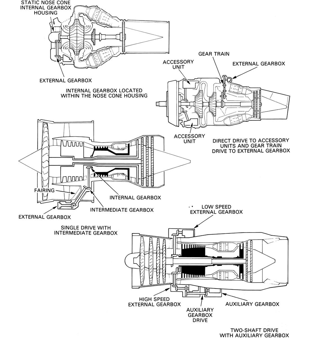
Thermal fatigue and a reduction in engine performance, due to the radial drive shaft disturbing the gas flow, creates greater problems within the turbine area than the compressor area. For any given engine, which incorporates an axial-flow compressor, the turbine area is smaller than that containing the compressor and therefore makes it physically easier to mount the gearbox within the compressor section. Centrifugal compressor engines can have limited available space, so the internal gearbox is located within a static nose cone or, in the case of a turbo-propeller engine, behind the propeller reduction gear as shown in Figure 8–1.
On multi-shaft engines, the choice of which compressor shaft is used to drive the internal gearbox is primarily dependent upon the ease of engine starting. This is achieved by rotating the compressor shaft, usually via an input torque from the external gearbox. In practice the high pressure system is invariably rotated in order to generate an airflow through the engine and the high pressure compressor shaft is therefore coupled to the internal gearbox.
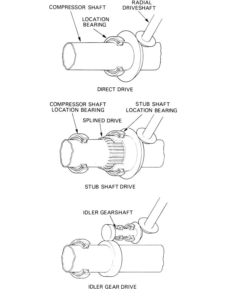
To minimize unwanted movement between the compressor shaft bevel gear and radial driveshaft bevel gear, caused by axial movement of the compressor shaft, the drive is taken by one of three basic methods (Figure 8–2). The least number of components is used when the compressor shaft bevel gear is mounted as close to the compressor shaft location bearing as possible, but a small amount of movement has to be accommodated within the meshing of the bevel gears. Alternatively, the compressor shaft bevel gear may be mounted on a stub shaft that has its own location bearing. The stub shaft is splined onto the compressor shaft that allows axial movement without affecting the bevel gear mesh. A more complex system utilizes an idler gear that meshes with the compressor shaft via straight spur gears, accommodating the axial movement, and drives the radial driveshaft via a bevel gear arrangement. The latter method was widely employed on early engines to overcome gear engagement difficulties at high speed.
To spread the load of driving accessory units, some engines take a second drive from the slower rotating low pressure shaft to a second external gearbox (Figure 8–1). This also has the advantage of locating the accessory units in two groups, thus overcoming the possibility of limited external space on the engine. When this method is used, an attempt is made to group the accessory units specific to the engine onto the high pressure system, since that is the first shaft to rotate, and the aircraft accessory units are driven by the low pressure system. A typical internal gearbox showing how both drives are taken is shown in Figure 8–3.

Radial Driveshaft
The purpose of a radial driveshaft is to transmit the drive from the internal gearbox to an accessory unit or the external gearbox. It also serves to transmit the high torque from the starter to rotate the high-pressure system for engine starting purposes. The driveshaft may be direct drive or via an intermediate gearbox.
To minimize the effect of the driveshaft passing through the compressor duct and disrupting the airflow, it is housed within the compressor support structure. On by-pass engines, the driveshaft is either housed in the outlet guide vanes or in a hollow streamlined radial fairing across the low-pressure compressor duct.
To reduce airflow disruption it is desirable to have the smallest driveshaft diameter as possible. The smaller the diameter, the faster the shaft must rotate to provide the same power. However, this raises the internal stress and gives greater dynamic problems, which result in vibration. A long radial driveshaft usually requires a roller bearing situated halfway along its length to give smooth running. This allows a rotational speed of approximately 25,000 rpm to be achieved with a shaft diameter of less than 1.5 inch without encountering serious vibration problems.
Direct Drive
In some early engines, a radial driveshaft was used to drive each, or in some instances a pair of, accessory units. Although this allowed each accessory unit to be located in any desirable location around the engine and decreased the power transmitted through individual gears, it necessitated a large internal gearbox. Additionally, numerous radial driveshafts had to be incorporated within the design. This led to an excessive amount of time required for disassembly and assembly of the engine for maintenance purposes.
In some instances the direct drive method may be used in conjunction with the external gearbox system when it is impractical to take a drive from a particular area of the engine to the external gearbox. For example, Figure 8–1 shows a turbo-propeller engine that requires accessories specific to the propeller reduction drive, but has the external gearbox located away from this area to receive the drive from the compressor shaft.
Gear Train Drive
When space permits, the drive may be taken to the external gearbox via a gear train (Figure 8–1). This involves the use of spur gears, sometimes incorporating a centrifugal breather. However, it is rare to find this type of drive system in current use.
Intermediate Gearbox
Intermediate gearboxes are employed when it is not possible to directly align the radial driveshaft with the external gearbox. To overcome this problem an intermediate gearbox is mounted on the high-pressure compressor case and redirects the drive, through bevel gears, to the external gearbox. An example of this layout is shown in Figure 8–1.
External Gearbox
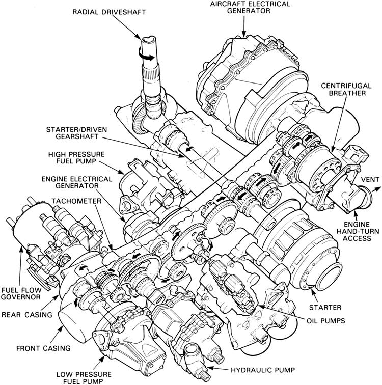
The external gearbox contains the drives for the accessories, the drive from the starter, and provides a mounting face for each accessory unit. Provision is also made for hand turning the engine, via the gearbox, for maintenance purposes. Figure 8–4 shows the accessory units that are typically found on an external gearbox.
The overall layout of an external gearbox is dictated by a number of factors. To reduce drag while the aircraft is flying it is important to present a low frontal area to the airflow. Therefore the gearbox is “wrapped” around the engine and may look, from the front, similar to a banana in shape. For maintenance purposes the gearbox is generally located on the underside of the engine to allow ground crew to gain access. However, helicopter installation design usually requires the gearbox to be located on the top of the engine for ease of access.
The starter/driven gearshaft (Figure 8–4) roughly divides the external gearbox into two sections. One section provides the drive for the accessories that require low power while the other drives the high power accessories. This allows the small and large gears to be grouped together independently and is an efficient method of distributing the drive for the minimum weight.
If any accessory unit fails, and is prevented from rotating, it could cause further failure in the external gearbox by shearing the teeth of the gear train. To prevent secondary failure from occurring, a weak section is machined into the driveshafts, known as a “shear-neck,” which is designed to fail and thus protect the other drives. This feature is not included for primary engine accessory units, such as the oil pumps, because these units are vital to the running of the engine and any failure would necessitate immediate shutdown of the engine.
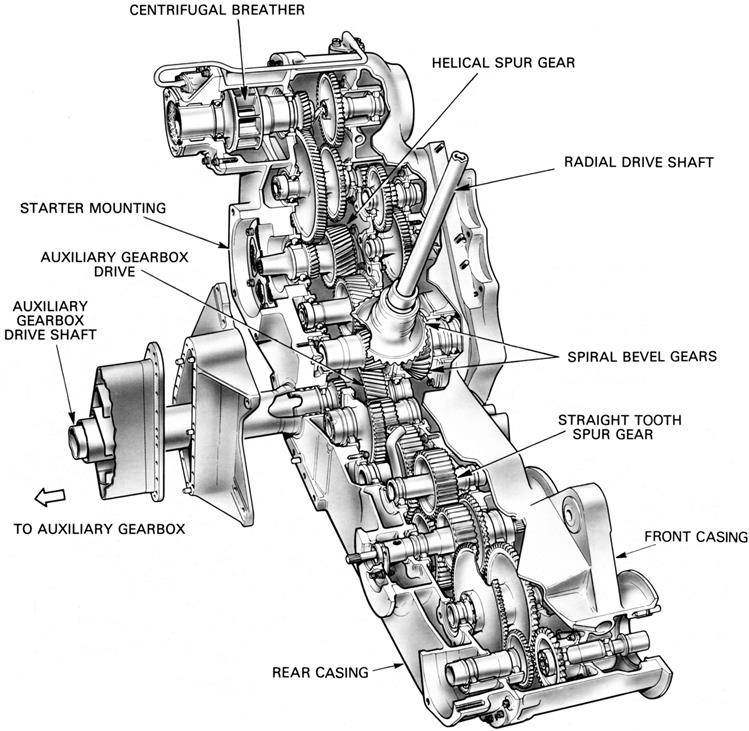
Since the starter provides the highest torque that the drive system encounters, it is the basis of design. The starter is usually positioned to give the shortest drive line to the engine core. This eliminates the necessity of strengthening the entire gear train, which would increase the gearbox weight. However, when an auxiliary gearbox is fitted the starter is moved along the gear train to allow the heavily loaded auxiliary gearbox drive to pass through the external gearbox. This requires the spur gears between the starter and starter/driven gearshaft to have a larger face width to carry the load applied by the starter (Figure 8–5).
When a drive is taken from two compressor shafts, as discussed previously, two separate gearboxes are required. These are mounted on either side of the compressor case and are generally known as the “low speed” and “high speed” external gearboxes.
Auxiliary Gearbox
An auxiliary gearbox is a convenient method of providing additional accessory drives when the configuration of an engine and airframe does not allow enough space to mount all of the accessory units on a single external gearbox.
A drive is taken from the external gearbox (Figure 8–5) to power the auxiliary gearbox, which distributes the appropriate gear ratio drive to the accessories in the same manner as the external gearbox.
Construction and Materials
Gears
The spur gears of the external or auxiliary gearbox gear train (Figures 8–4 and 8–5) are mounted between bearings supported by the front and rear casings that are bolted together. They transmit the drive to each accessory unit, which is normally between 5000 and 6000 rpm for the accessory units and approximately 20,000 rpm for the centrifugal breather.
All gear meshes are designed with “hunting tooth” ratios that ensure that each tooth of a gear does not engage between the same set of opposing teeth on each revolution. This spreads any wear evenly across all teeth.
Spiral bevel gears are used for the connection of shafts whose axes are at an angle to one another but in the same plane. The majority of gears within a gear train are of the straight spur gear type; those with the widest face carry the greatest loads. For smoother running, helical gears are used but the resultant end thrust caused by this gear tooth pattern must be catered for within the mounting of the gear.
Gearbox Sealing
Sealing of the accessory drive system is primarily concerned with preventing oil loss. The internal gearbox has labyrinth seals where the static casing mates with the rotating compressor shaft. For some of the accessories mounted on the external gearbox, an air-blown pressurized labyrinth seal is employed. This prevents oil from the gearbox entering the accessory unit and also prevents contamination of the gearbox, and hence engine, in the event of an accessory failure. The use of an air-blown seal results in a gearbox pressure of about 3 lbs. per sq. in. above atmospheric pressure. To supplement a labyrinth seal, an “oil thrower ring” may be used. This involves the leakage oil running down the driving shaft and being flung outwards by a flange on the rotating shaft. The oil is then collected and returned to the gearbox.
Materials
To reduce weight, the lightest materials possible are used. The internal gearbox casing is cast from aluminum, but the low environmental temperatures that an external gearbox is subjected to allow the use of magnesium castings, which are lighter still. The gears are manufactured from non-corrosion resistant steels for strength and toughness. They are case hardened to give a very hard wear resistant skin and feature accurately ground teeth for smooth gear meshing.
Starting and Ignition Systems2
Two separate systems are required to ensure that a gas turbine engine will start satisfactorily. Firstly, provision must be made for the compressor and turbine to be rotated up to a speed at which adequate air passes into the combustion system to mix with fuel from the fuel spray nozzles. Secondly, provision must be made for ignition of the air/fuel mixture in the combustion system. During engine starting the two systems must operate simultaneously, yet it must also be possible to motor the engine over without ignition for maintenance checks and to operate only the ignition system for relighting during flight.
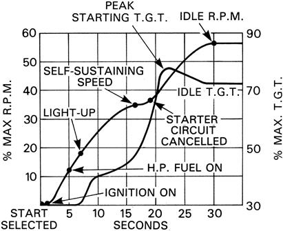
The functioning of both systems is coordinated during a starting cycle and their operation is automatically controlled after the initiation of the cycle by an electrical circuit. A typical sequence of events during the start of a turbo-jet engine is shown in Figure 8–6.
Methods of Starting
The starting procedure for all jet engines is basically the same, but can be achieved by various methods. The type and power source for the starter varies in accordance with engine and aircraft requirements. Some use electrical power; others use gas, air, or hydraulic pressure, and each has its own merits. For example, a military aircraft requires the engine to be started in the minimum time and, when possible, to be completely independent of external equipment. A commercial aircraft, however, requires the engine to be started with the minimum disturbance to the passengers and by the most economical means. Whichever system is used, reliability is of prime importance.
The starter motor must produce a high torque and transmit it to the engine rotating assembly in a manner that provides smooth acceleration from rest up to a speed at which the gas flow through the engine provides sufficient power for the engine turbine to take over.
Electric
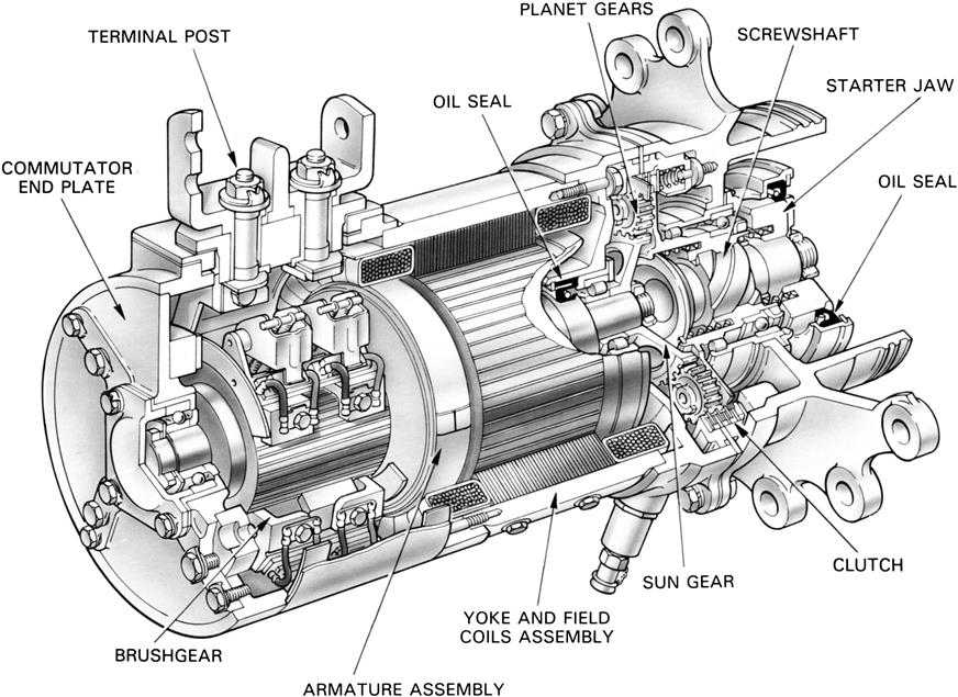
The electric starter is usually a direct current (D.C.) electric motor coupled to the engine through a reduction gear and ratchet mechanism, or clutch, which automatically disengages after the engine has reached a self-sustaining speed (Figure 8–7).
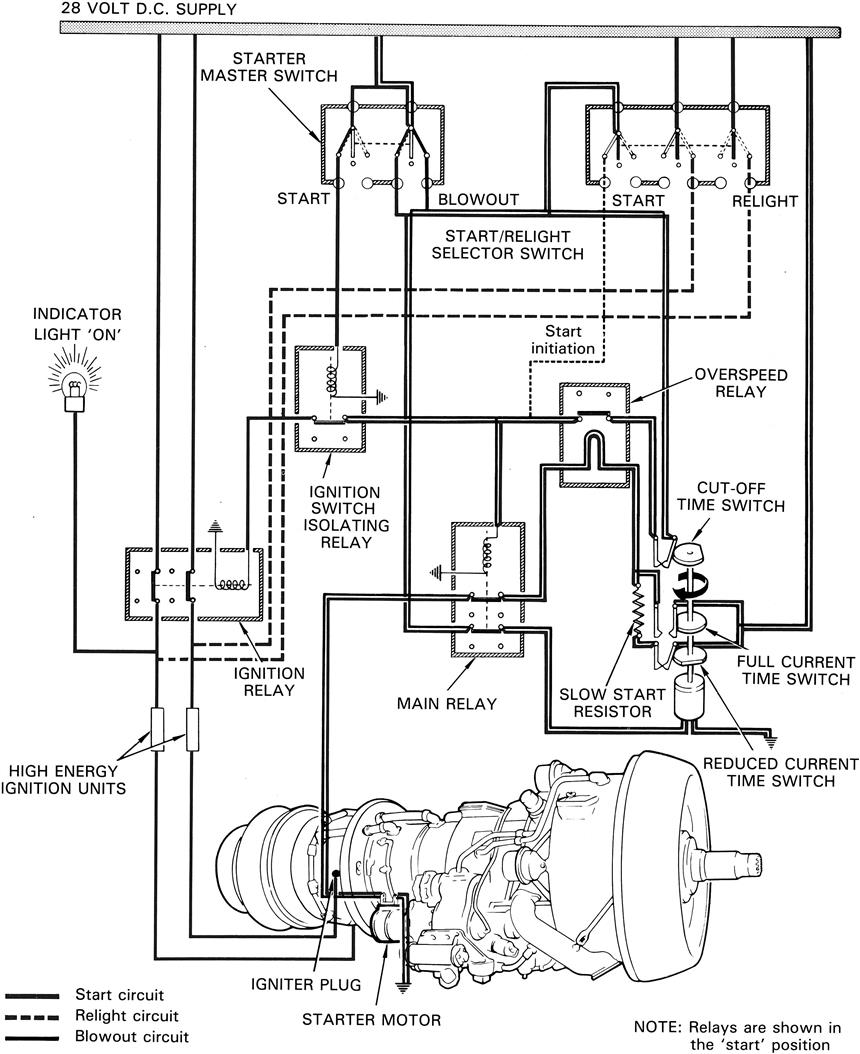
The electrical supply may be of a high or low voltage and is passed through a system of relays and resistances to allow the full voltage to be progressively built up as the starter gains speed. It also provides the power for the operation of the ignition system. The electrical supply is automatically cancelled when the starter load is reduced after the engine has satisfactorily started or when the time cycle is completed. A typical electrical starting system is shown in Figure 8–8.
Cartridge
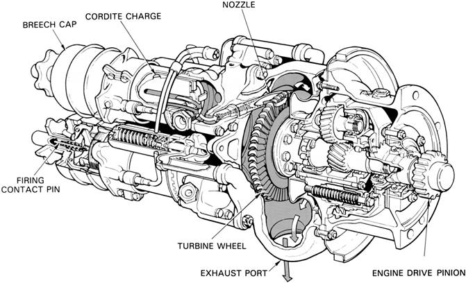
Cartridge starting is sometimes used on military engines and provides a quick independent method of starting. The starter motor is basically a small impulse-type turbine that is driven by high velocity gases from a burning cartridge. The power output of the turbine is passed through a reduction gear and an automatic disconnect mechanism to rotate the engine. An electrically fired detonator initiates the burning of the cartridge charge. As a cordite charge provides the power supply for this type of starter, the size of the charge required may well limit the use of the cartridge starters. A triple-breech starter is illustrated in Figure 8–9.
Iso-Propyl-Nitrate
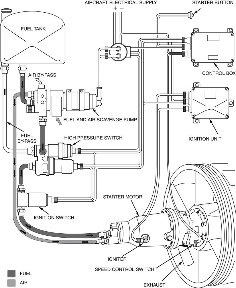
This type of starter provides a high power output and gives rapid starting characteristics. It has a turbine that transmits power through a reduction gear to the engine. In this instance, the turbine is rotated by high-pressure gases resulting from the combustion of iso-propyl-nitrate. This fuel is sprayed into a combustion chamber, which forms part of the starter, where it is electrically ignited by a high-energy ignition system. A pump supplies the fuel to the combustion chamber from a storage tank and an air pump scavenges the starter combustion chamber of fumes before each start. Operation of the fuel and air pumps, ignition systems, and cycle cancellation is electrically controlled by relays and time switches. An iso-propyl-nitrate starting system is shown in Figure 8–10.
Air
Air starting is used on most commercial and some military jet engines. It has many advantages over other starting systems, and is comparatively light, simple, and economical to operate.
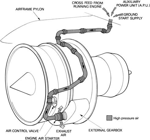
An air starter motor transmits power through a reduction gear and clutch to the starter output shaft, which is connected to the engine. A typical air starter motor is shown in Figure 8–11.
The starter turbine is rotated by air taken from an external ground supply, an auxiliary power unit (A.P.U.) or as a cross-feed from a running engine. The air supply to the starter is controlled by an electrically operated control and pressure-reducing valve that is opened when an engine start is selected and is automatically closed at a predetermined starter speed. The clutch also automatically disengages as the engine accelerates up to idling rpm and the rotation of the starter ceases. A typical air starting system is shown in Figure 8–12.
A combustor starter is sometimes fitted to an engine incorporating an air starter and is used to supply power to the starter when an external supply of air is not available. The starter unit has a small combustion chamber into which high pressure air, from an aircraft-mounted storage bottle, and fuel, from the engine fuel system, are introduced. Control valves regulate the air supply that pressurizes a fuel accumulator to give sufficient fuel pressure for atomization and also activates the continuous ignition system. The fuel/air mixture is ignited in the combustion chamber and the resultant gas is directed onto the turbine of the air starter. An electrical circuit is provided to shut off the air supply, which in turn terminates the fuel and ignition systems on completion of the starting cycle.
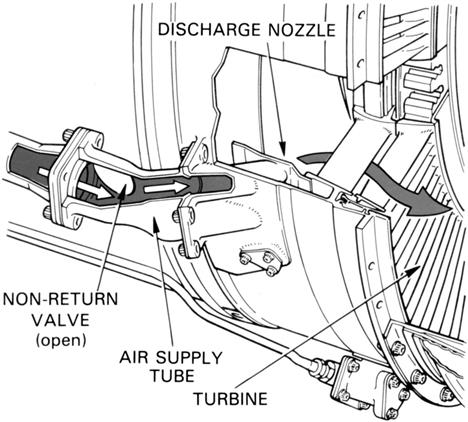
Some turbo-jet engines are not fitted with starter motors, but use air impingement onto the turbine blades as a means of rotating the engine. The air is obtained from an external source, or from an engine that is running, and is directed through non-return valves and nozzles onto the turbine blades. A typical method of air impingement starting is shown in Figure 8–13.
Gas Turbine
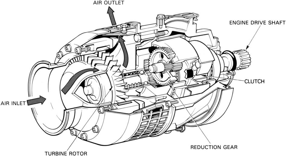
A gas turbine starter is used for some jet engines and is completely self-contained. It has its own fuel and ignition system, starting system (usually electric or hydraulic), and self-contained oil system. This type of starter is economical to operate and provides a high power output for a comparatively low weight.
The starter consists of a small, compact gas turbine engine, usually featuring a turbine-driven centrifugal compressor, a reverse flow combustion system, and a mechanically independent free-power turbine. The free-power turbine is connected to the main engine via a two-stage epicyclic reduction gear, automatic clutch and output shaft. A typical gas turbine starter is shown in Figure 8–14.
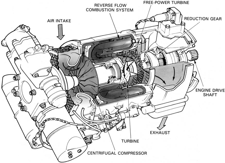
On initiation of the starting cycle, the gas turbine starter is rotated by its own starter motor until it reaches self-sustaining speed, when the starting and ignition systems are automatically switched off. Acceleration then continues up to a controlled speed of approximately 60,000 rpm. At the same time as the gas turbine starter engine is accelerating, the exhaust gas is being directed, via nozzle guide vanes, onto the free-power turbine to provide the drive to the main engine. Once the main engine reaches self-sustaining speed, a cut-out switch operates and shuts down the gas turbine starter. As the starter runs down, the clutch automatically disengages from the output shaft and the main engine accelerates up to idling rpm under its own power.
Hydraulic
Hydraulic starting is used for starting some small jet engines. In most applications, one of the engine-mounted hydraulic pumps is utilized and is known as a pump/starter, although other applications may use a separate hydraulic motor. Methods of transmitting the torque to the engine may vary, but a typical system would include a reduction gear and clutch assembly. Power to rotate the pump/starter is provided by hydraulic pressure from a ground supply unit and is transmitted to the engine through the reduction gear and clutch. The starting system is controlled by an electrical circuit that also operates hydraulic valves so that on completion of the starting cycle the pump/starter functions as a normal hydraulic pump.
Ignition
High-energy (H.E.) ignition is used for starting all jet engines and a dual system is always fitted. Each system has an ignition unit connected to its own igniter plug, the two plugs being situated in different positions in the combustion system.
Each H.E. ignition unit receives a low voltage supply, controlled by the starting system electrical circuit, from the aircraft electrical system. The electrical energy is stored in the unit until, at a predetermined value, the energy is dissipated as a high voltage, high amperage discharge across the igniter plug.
Ignition units are rated in joules (one joule equals one watt per second). They are designed to give outputs that may vary according to requirements. A high value output (e.g., 12 joule) is necessary to ensure that the engine will obtain a satisfactory relight at high altitudes and is sometimes necessary for starting. However, under certain flight conditions, such as icing or takeoff in heavy rain or snow, it may be necessary to have the ignition system continuously operating to give an automatic relight should flame extinction occur. For this condition, a low value output (e.g., 3–6 joule) is preferred because it results in a longer life of the igniter plug and ignition unit. Consequently, to suit all engine operating conditions, a combined system giving a high and low value output is favored. Such a system would consist of one unit emitting a high output to one igniter plug, and a second unit giving a low output to a second igniter plug. However, some ignition units are capable of supplying both high and low outputs, the value being pre-selected as required.
An ignition unit may be supplied with direct current (D.C.) and operated by a trembler mechanism or a transistor chopper circuit, or supplied with alternating current (A.C.) and operated by a transformer. The operation of each type of unit is described in the subsequent paragraphs.
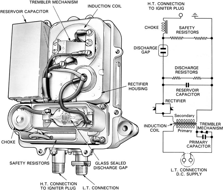
The ignition unit shown in Figure 8–15 is a typical D.C. trembler-operated unit. An induction coil, operated by the trembler mechanism, charges the reservoir capacitor (condenser) through a high voltage rectifier. When the voltage in the capacitor is equal to the breakdown value of a sealed discharge gap, the energy is discharged across the face of the igniter plug. A choke is fitted to extend the duration of the discharge and a discharge resistor is fitted to ensure that any residual stored energy in the capacitor is dissipated within 1 minute of the system being switched off. A safety resistor is fitted to enable the unit to operate safely, even when the high tension lead is disconnected and isolated.
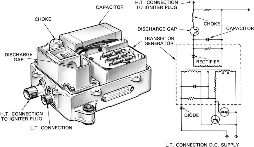
Operation of the transistorized ignition unit is similar to that of the D.C. trembler-operated unit, except that the trembler-unit is replaced by a transistor chopper circuit. A typical transistorized unit is shown in Figure 8–16: such a unit has many advantages over the trembler-operated unit because it has no moving parts and gives a much longer operating life. The size of the transistorized unit is reduced and its weight is less than that of the trembler-operated unit.
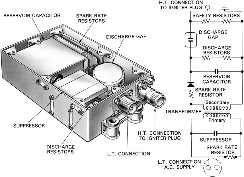
The A.C. ignition unit, shown in Figure 8–17, receives an alternating current that is passed through a transformer and rectifier to charge a capacitor. When the voltage in the capacitor is equal to the breakdown value of a sealed discharge gap, the capacitor discharges the energy across the face of the igniter plug. Safety and discharge resistors are fitted as in the trembler-operated unit.
There are two basic types of igniter plug; the constricted or constrained air gap type and the shunted surface discharge type. The air gap type is similar in operation to the conventional reciprocating engine spark plug, but has a larger air gap between the electrode and body for the spark to cross. A potential difference of approximately 25,000 volts is required to ionize the gap before a spark will occur. This high voltage requires very good insulation throughout the circuit. The surface discharge igniter plug (Figure 8–18) has the end of the insulator formed by a semi-conducting pellet that permits an electrical leakage from the central high-tension electrode to the body. This ionizes the surface of the pellet to provide a low resistance path for the energy stored in the capacitor. The discharge takes the form of a high intensity flashover from the electrode to the body and only requires a potential difference of approximately 2000 volts for operation.
The normal spark rate of a typical ignition system is between 60 and 100 sparks per minute. Periodic replacement of the igniter plug is necessary due to the progressive erosion of the igniter electrodes caused by each discharge.
The igniter plug tip protrudes approximately 0.1 inch into the flame tube. During operation the spark penetrates a further 0.75 inch. The fuel mixture is ignited in the relatively stable boundary layer, which then propagates throughout the combustion system.
Relighting
The jet engine requires facilities for relighting should the flame in the combustion system be extinguished during flight. However, the ability of the engine to relight will vary according to the altitude and forward speed of the aircraft. A typical relight envelope, showing the flight conditions under which an engine will obtain a satisfactory relight, is shown in Figure 8–19. Within the limits of the envelope, the airflow through the engine will rotate the compressor at a speed satisfactory for relighting; all that is required therefore, provided that a fuel supply is available, is the operation of the ignition system. This is provided for by a separate switch that operates only the ignition system.
Ice Protection Systems3
With aeroengines, icing of the engine and the leading edges of the intake duct can occur during flight through clouds containing supercooled water droplets or during ground operation in freezing fog. Protection against ice formation may be required since icing of these regions can restrict considerably the airflow through the engine, causing a loss in performance and possible malfunction of the engine.
Additionally, damage may result from ice breaking away and being ingested into the engine or hitting the acoustic material lining the intake duct.
Given4 the right conditions, icing can occur with land-based engines as well. With land-based engines, inlet duct heating may be used (exercising care that the melted ice does not cause damage to downstream airfoils). Inlet air filters (the “huff & puff” type that drop ice formed on filter cartridges with a blast of air) can also provide anti-icing protection.
An3 ice protection system must effectively prevent ice formation within the operational requirements of the particular application. The system must be reliable, easy to maintain, present no excessive weight penalty, and cause no serious loss in engine performance when in operation.
Analyses are carried out to determine whether ice protection is required and, if so, the heat input required to limit ice build-up to acceptable levels. Figure 8–20 illustrates the areas of a turbo-fan engine typically considered for ice protection.
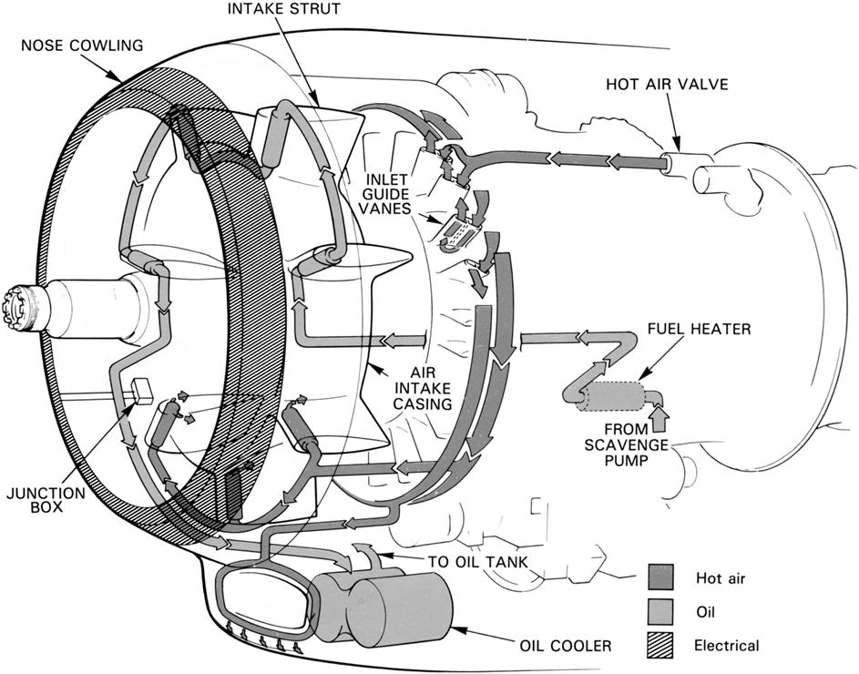
There are two basic systems of ice protection; turbo-jet engines generally use a hot air supply (Figure 8–21), and turbo-propeller engines use electrical power or a combination of electrical power and hot air.
Protection may be supplemented by the circulation of hot oil around the air intake as shown in Figure 8–22. The hot air system is generally used to prevent the formation of ice and is known as an anti-icing system. The electrical power system is used to break up ice that has formed on surfaces and is known as a de-icing system.
Hot Air System
The hot air system provides surface heating of the engine and/or power plant where ice is likely to form. The protection of rotor blades is rarely necessary, because any ice accretions are dispersed by centrifugal action. If stators are fitted upstream of the first rotating compressor stage these may require protection. If the nose cone rotates it may not need anti-icing if its shape, construction, and rotational characteristics are such that likely icing is acceptable.
The hot air for the anti-icing system is usually taken from the high-pressure compressor stages. It is ducted through pressure regulating valves to the parts requiring anti-icing. Spent air from the nose cowl anti-icing system may be exhausted into the compressor intake or vented overboard.
If the nose cone is anti-iced its hot air supply may be independent or integral with that of the nose cowl and compressor stators. For an independent system, the nose cone is usually anti-iced by a continuous unregulated supply of hot air via internal ducting from the compressor.
The pressure regulating valves are electrically actuated by manual selection, or automatically by signals from the aircraft ice detection system. The valves prevent excessive pressures being developed in the system, and act also as an economy device at the higher engine speeds by limiting the air offtake from the compressor, thus preventing an excessive loss in performance. The main valve may be manually locked in a pre-selected position prior to takeoff in the event of a valve malfunction, prior to replacement.
Electrical System
The electrical system of ice protection is generally used for turbo-propeller engine installations, as this form of protection is necessary for the propellers. The surfaces that require electrical heating are the air intake cowling of the engine, the propeller blades and spinner, and, when applicable, the oil cooler air intake cowling.
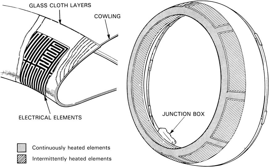
Electrical heating pads are bonded to the outer skin of the cowlings. They consist of strip conductors sandwiched between layers of neoprene, or glass cloth impregnated with epoxy resin. To protect the pads against rain erosion, they are coated with a special, polyurethane-based paint. When the de-icing system is operating, some of the areas are continuously heated to prevent an ice cap forming on the leading edges and also to limit the size of the ice that forms on the areas that are intermittently heated (Figure 8–23).
Electrical power is supplied by a generator and, to keep the size and weight of the generator to a minimum, the de-icing electrical loads are cycled between the engine, propeller, and, sometimes, the airframe.
When the ice protection system is in operation, the continuously heated areas prevent any ice forming, but the intermittently heated areas allow ice to form, during their “heat-off” period. During the “heat-on” period, adhesion of the ice is broken and it is then removed by aerodynamic forces.
The cycling time of the intermittently heated elements is arranged to ensure that the engine can accept the amount of ice that collects during the “heat-off” period and yet ensure that the “heat-on” period is long enough to give adequate shedding, without causing any run-back icing to occur behind the heated areas.
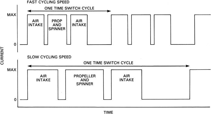
A two-speed cycling system is often used to accommodate the propeller and spinner requirements; a “fast” cycle at the high air temperatures when the water concentration is usually greater and a “slow” cycle in the lower temperature range. A typical cycling sequence chart is shown in Figure 8–24.
Fire Protection Systems5
All gas turbine engines and their associated installation systems incorporate features that minimize the possibility of an engine fire. It is essential, however, that if a failure does take place and results in a fire, there is provision for the immediate detection and rapid extinction of the fire, and for the prevention of it spreading. The detection and extinguishing systems must add as little weight to the installation as possible.
Prevention of Engine Fire Ignition
An engine/powerplant is designed to ensure that the prevention of engine fire ignition is achieved as far as possible. In most instances a dual failure is necessary before a fire can occur.
Most of the potential sources of flammable fluids are isolated from the “hot end” of the engine. External fuel and oil system components and their associated pipes are usually located around the compressor casings, in a “cool” zone, and are separated by a fireproof bulkhead from the combustion, turbine and jet pipe area, or “hot” zone. The zones may be ventilated, as described later, to prevent the accumulation of flammable vapors.
All pipes that carry fuel, oil, or hydraulic fluid are made fire resistant/proof to comply with fire regulations, and all electrical components and connections are made explosion-proof. Sparking caused by discharge of static electricity is prevented by bonding all aircraft and engine components. This gives electrical continuity between all the components and makes them incapable of igniting flammable vapor.
On some engines, tubes carrying flammable fluids in “hot areas” of the engine are constructed with a double skin. Should a fracture of the main fluid carrying tube occur the outer skin will contain any leakage, so preventing any possible fire ignition.
The powerplant cowlings are provided with an adequate drainage system to remove flammable fluids from the nacelle, bay, or pod, and all seal leakages from components are drained overboard at a position such that fluid cannot re-enter the pod and create a fire hazard.
Spontaneous ignition can be minimized on aircraft flying at high Mach numbers by ducting boundary layer bleed air around the engine. However, if ignition should occur, this high velocity air stream may have to be shut off; otherwise it would increase the flame intensity and reduce the effectiveness of the extinguishing system by rapid dispersal of the extinguishant.
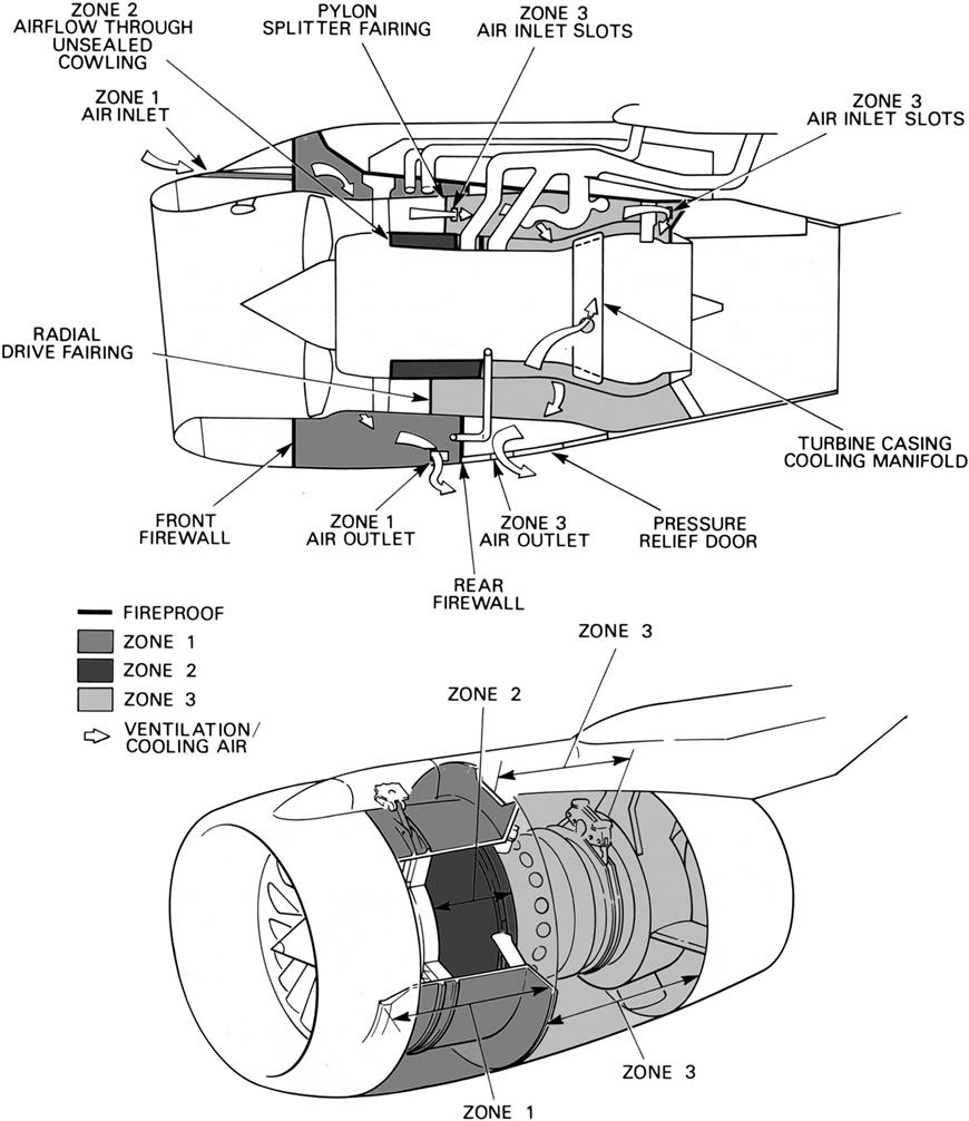
External Cooling and Ventilation
The engine bay or pod is usually cooled and ventilated by atmospheric air being passed around the engine and then vented overboard (Figure 8–25). Convection cooling during ground running may be provided by using an internal cooling outlet vent as an ejector system. An important function of the airflow is to purge any flammable vapors from the engine compartment. By keeping the airflow minimal, the power plant drag is minimized and, as the required quantity of fire extinguishant is in proportion to the zonal airflow, any fire outbreak would be of low intensity.
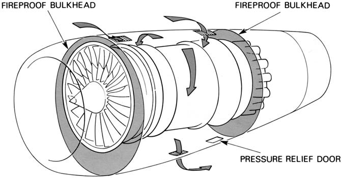
On some engines a fireproof bulkhead is also provided to separate the “cool” area or zone of the engine, which contains the fuel, oil, hydraulic, and electrical systems from the “hot” area surrounding the combustion, turbine and exhaust sections of the engine. Differential pressures can be created in the two zones by calibration of the inlet and outlet apertures to prevent the spread of fire from the hot zone.
Figure 8–26 shows a more complex cooling and ventilation system used on a turbo-fan engine. Air is induced from the intake duct and also delivered from the fan to provide multi-zone cooling, each zone having its own calibrated cooling flow.
Fire Detection
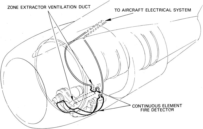
The rapid detection of a fire is essential to minimize the fire period before engine shutdown drill and release of extinguishant is effected. It is also extremely important that a fire detection system will not give a false fire warning resulting from short circuiting caused by chafing or the ingress of moisture in the case of electrically operated systems and chafes of the capillary resulting in loss of the contained gas in the case of the gas filled continuous element sensing type.
A detection system may consist of a number of strategically located detector units, or be of the continuous element (gas-filled or electrical) sensing type that can be shaped and attached to pre-formed tubes. The sensing element can be routed across outlet orifices, such as a zone extractor ventilation duct, to give early detection of a fire (Figure 8–27).
In the case of electrical systems the presence of a fire is signaled by a change in the electrical characteristics of the detector circuit, according to the type of detector, be it thermistor, thermocouple, or electrical continuous element. In these cases the change in temperature creates the signal that, through an amplifier, operates the warning indicator.
Both the thermocouple and thermistor detectors have properties making them ideally suited to this application. The thermocouple comprises two dissimilar metals that are joined together to form two junctions. As the temperature difference between the two junctions increases an E.M.F. is produced in the circuit and it is this E.M.F. that triggers the fire warning displays. The thermistor consists of a semiconductor material whose resistance changes as temperature increases, with a corresponding change in the current flowing in the circuit. It is this change in the current that operates the warning indicators. A thermistor may be used as a single point detector or as a continuous element sensor.
Another form of continuous element sensor takes the form of a capacitor consisting of a tube containing a dielectric material with a conductor running through the center. A voltage difference is applied between the tube and the center conductor. As the temperature increases then the properties of the dielectric change with a corresponding change in the value of capacitance. This change of capacitance is displayed as a fire warning.
The gas filled detector consists of stainless steel tubing filled with gas absorbent material and in the event of a fire or overheat condition the temperature rise will cause the core of the sensing loop to expel the absorbed active gas into the sealed tube causing a rapid increase in pressure. This build-up of pressure is sensed by the detector alarm switch. Should the sensing loop become damaged causing a loss of the pressurized gas, an integrity switch will indicate a detection loop fault on the appropriate engine. Fire indication is given by a warning light and bell.
At high Mach numbers, the considerably higher temperature levels may be such as to render the thermistor or thermocouple fire detection system unsatisfactory. Thermal detectors that sense either a temperature rise, or a rate of temperature rise, may therefore prove most suitable.
Alternatives to the above types are surveillance detectors that respond to light radiation from a fire. These may be made so sensitive that they respond only to the ultraviolet and infrared rays emitted from a kerosene fire.
Fire Containment
An engine fire must be contained within the powerplant and not be allowed to spread to other parts of the aircraft. The cowlings that surround the engine are usually made of aluminum alloys, which would be unable to contain a fire when the aircraft is static. During flight, however, the airflow around the cowlings provides sufficient cooling to render them fireproof. Fireproof bulkheads and any cowlings that are not affected by a cooling airflow and sections of cowlings around certain outlets that may act as “flame-holders” are usually manufactured from steel or titanium.
Fire Extinguishing
Before a fire extinguishing system is operated, the engine must be stopped to reduce the discharge of flammable fluids and air into the fire area. Any valves, such as the low-pressure fuel cock, that control the flow of flammable fluid must be situated outside the “hot” zone to prevent fire damage rendering them inoperative.
After a fire has been extinguished, no attempt must be made to start the engine again as this would probably reestablish the fluid leak and the ignition source that were the original causes of the fire. Furthermore, the extinguishing system may be exhausted.
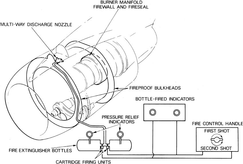
The extinguishant that is used for engine fires is usually one of the Freon compounds. Pressurized containers are provided for the extinguishant and these are located outside the fire risk zone. When the relevant electrical circuit is manually operated, the extinguishant is discharged from the containers through a series of perforated spray pipes or nozzles into the fire (Figure 8–28). The discharge must be sufficient to give a predetermined concentration of extinguishant for a period that may vary between 0.5 seconds and 2 seconds. The system is generally one that enables two separate discharges to be made.
Engine Overheat Detection
Turbine overheat does not constitute a serious fire risk. Detection of an overheat condition, however, is essential to enable the pilot to stop the engine before mechanical or material damage results.
A warning system of a similar type to the fire detection system, or thermocouples suitably positioned in the cooling airflow, may be used to detect excessive temperatures. Thermal switches positioned in the engine overboard air vents, such as the cooling air outlets, may also be included to give an additional warning.
Water Injection Systems6
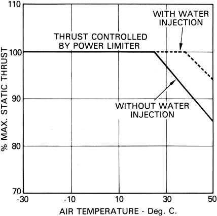
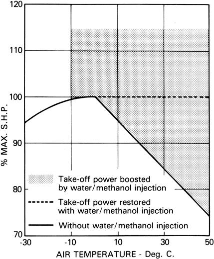
The maximum power output of a gas turbine engine depends to a large extent upon the density or weight of the airflow passing through the engine. There is, therefore, a reduction in thrust or shaft horsepower as the atmospheric pressure decreases with altitude, and/or the ambient air temperature increases. Under these conditions, the power output can be restored or, in some instances, boosted for takeoff by cooling the airflow with water or water/methanol mixture (coolant). When methanol is added to the water it gives anti-freezing properties and also provides an additional source of fuel. A typical turbo-jet engine thrust restoration curve is shown in Figure 8–29 and a turbo-propeller engine power restoration and boost curve is shown in Figure 8–30.
There are two basic methods of injecting the coolant into the airflow. Some engines have the coolant sprayed directly into the compressor inlet, but the injection of coolant into the combustion chamber inlet is usually more suitable for axial flow compressor engines. This is because a more even distribution can be obtained and a greater quantity of coolant can be satisfactorily injected.
When water/methanol mixture is sprayed into the compressor inlet, the temperature of the compressor inlet air is reduced and consequently the air density and thrust are increased. If water only was injected, it would reduce the turbine inlet temperature, but with the addition of methanol the turbine inlet temperature is restored by the burning of methanol in the combustion chamber. Thus the power is restored without having to adjust the fuel flow.
The injection of coolant into the combustion chamber inlet increases the mass flow through the turbine, relative to that through the compressor. The pressure and temperature drop across the turbine is thus reduced and this results in an increased jet pipe pressure, which in turn gives additional thrust. The consequent reduction in turbine inlet temperature, due to water injection, enables the fuel system to schedule an increase of fuel flow to a value that gives an increase in the maximum rotational speed of the engine, thus providing further additional thrust. Where methanol is used with the water, the turbine inlet temperature is restored, or partially restored, by the burning of the methanol in the combustion chamber.
Compressor Inlet Injection
The compressor inlet injection system shown in Figure 8–31 is a typical system for a turbo-propeller engine. When the injection system is switched on, water/methanol mixture is pumped from an aircraft-mounted tank to a control unit. The control unit meters the flow of mixture to the compressor inlet through a metering valve that is operated by a servo piston. The servo system uses engine oil as an operating medium, and a servo valve regulates the supply of oil. The degree of servo valve opening is set by a control system that is sensitive to propeller shaft torque oil pressure and to atmospheric air pressure acting on a capsule assembly.
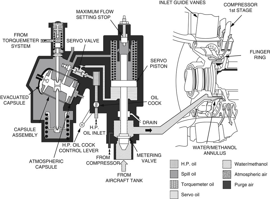
The control unit high-pressure oil cock control lever is interconnected to the throttle control system in such a manner that, until the throttle is moved towards the takeoff position, the oil cock remains closed, and thus the metering valve remains closed, preventing any mixture flowing to the compressor inlet. Movement of the throttle control to the takeoff position opens the oil cock, and the oil pressure passes through the servo valve to open the metering valve by means of the servo piston.
Combustion Chamber Injection
The combustion chamber injection system shown in Figure 8–32 is a typical system for a turbo-jet engine. The coolant flows from an aircraft-mounted tank to an air-driven turbine pump that delivers it to a water flow sensing unit. The water passes from the sensing unit to each fuel spray nozzle and is sprayed from two jets onto the flame tube swirl vanes, thus cooling the air passing into the combustion zone. The water pressure between the sensing unit and the discharge jets is sensed by the fuel control system, which automatically resets the engine speed governor to give a higher maximum engine speed.
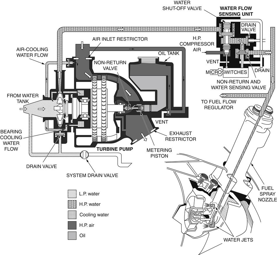
The water flow sensing unit opens only when the correct pressure difference is obtained between compressor delivery air pressure and water pressure. The system is brought into operation when the engine throttle lever is moved to the takeoff position, causing microswitches to operate and select the air supply for the turbine pump.
The sensing unit also forms a non-return valve to prevent air pressure feeding back from the discharge jets and provides for the operation of an indicator light to show when water is flowing.
Systems Unique to Aircraft Engine Applications
Thrust Reversal7
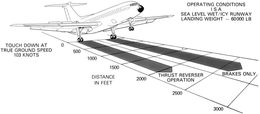
Modern aircraft brakes are very efficient but on wet, icy, or snow covered runways this efficiency may be reduced by the loss of adhesion between the aircraft tire and the runway thus creating a need for an additional method of bringing the aircraft to rest within the required distance.
A simple and effective way to reduce the aircraft landing run on both dry and slippery runways is to reverse the direction of the exhaust gas stream, thus using engine power as a deceleration force. Thrust reversal has been used to reduce airspeed in flight but it is not commonly used on modern aircraft. The difference in landing distances between an aircraft without reverse thrust and one using reverse thrust is illustrated in Figure 8–33.
On high by-pass ratio (fan) engines, reverse thrust action is achieved by reversing the fan (cold stream) airflow. It is not necessary to reverse the exhaust gas flow (hot stream) as the majority of the engine thrust is derived from the fan.
On propeller-powered aircraft, reverse thrust action is obtained by changing the pitch of the propeller blades. This is usually achieved by a hydro-mechanical system, which changes the blade angle to give the braking action under the response of the power or throttle lever in the aircraft.
Ideally, the gas should be directed in a completely forward direction. It is not possible, however, to achieve this, mainly for aerodynamic reasons, and a discharge angle of approximately 45° is chosen. Therefore, the effective power in reverse thrust is proportionately less than the power in forward thrust for the same throttle angle.
Principles of Operation
There are several methods of obtaining reverse thrust on turbo-jet engines; three of these are shown in Figure 8–34 and explained in the following paragraphs.
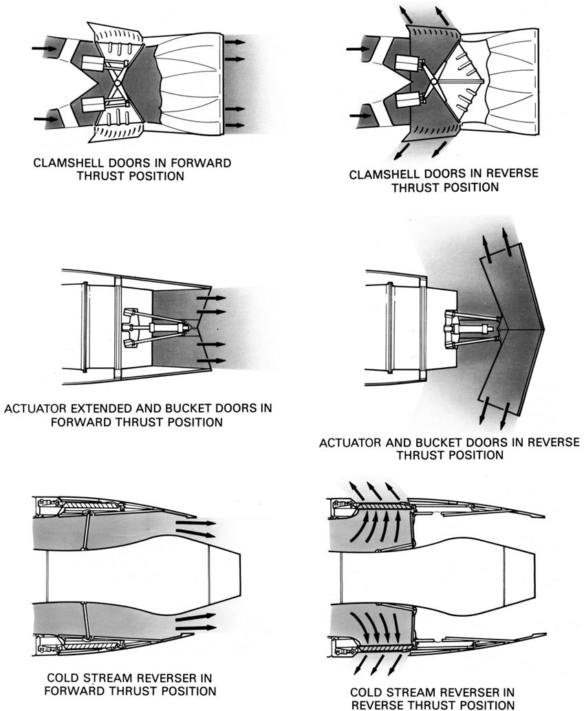
One method uses clamshell-type deflector doors to reverse the exhaust gas stream and a second uses a target system with external type doors to do the same thing. The third method used on fan engines utilizes blocker doors to reverse the cold stream airflow.
Methods of reverse thrust selection and the safety features incorporated in each system described are basically the same. A reverse thrust lever in the crew compartment is used to select reverse thrust; the lever cannot be moved to the reverse thrust position unless the engine is running at a low power setting, and the engine cannot be opened up to a high power setting if the reverser fails to move into the full reverse thrust position. Should the operating pressure fall or fail, a mechanical lock holds the reverser in the forward thrust position; this lock cannot be removed until the pressure is restored. Operation of the thrust reverser system is indicated in the crew compartment by a series of lights.
Clamshell Door System
The clamshell door system is a pneumatically operated system, shown in detail in Figure 8–35. Normal engine operation is not affected by the system, because the ducts through which the exhaust gases are deflected remain closed by the doors until reverse thrust is selected by the pilot.
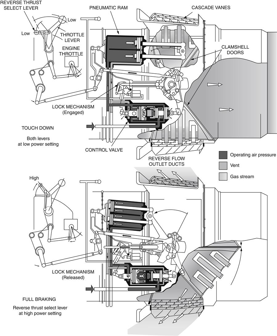
On the selection of reverse thrust, the doors rotate to uncover the ducts and close the normal gas stream exit. Cascade vanes then direct the gas stream in a forward direction so that the jet thrust opposes the aircraft motion.
The clamshell doors are operated by pneumatic rams through levers that give the maximum load to the doors in the forward thrust position; this ensures effective sealing at the door edges, so preventing gas leakage. The door bearings and operating linkage operate without lubrication at temperatures of up to 600°C.
Bucket Target System
The bucket target system is hydraulically actuated and uses bucket-type doors to reverse the hot gas stream. The thrust reverser doors are actuated by means of a conventional pushrod system. A single hydraulic powered actuator is connected to a drive idler, actuating the doors through a pair of pushrods (one for each door).
The reverser doors are kept in synchronization through the drive idler. The hydraulic actuator incorporates a mechanical lock in the stowed (actuator extended) position.
In the forward thrust mode (stowed) the thrust reverser doors form the convergent-divergent final nozzle for the engine.
Cold Stream Reverser System
The cold stream reverser system (Figure 8–36) can be actuated by an air motor, the output of which is converted to mechanical movement by a series of flexible drives, gearboxes and screw jacks, or by a system incorporating hydraulic rams.
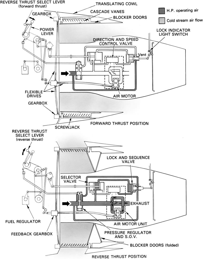
When the engine is operating in forward thrust, the cold stream final nozzle is “open” because the cascade vanes are internally covered by the blocker doors (flaps) and externally by the movable (translating) cowl; the latter item also serves to reduce drag.
On selection of reverse thrust, the actuation system moves the translating cowl rearwards and at the same time folds the blocker doors to blank off the cold stream final nozzle, thus diverting the airflow through the cascade vanes.
Turbo-Propeller Reverse Pitch System
As mentioned earlier, reverse thrust action is affected on turbo-propeller powered aircraft by changing the pitch of the propeller blades through a hydro-mechanical pitch control system (Figure 8–37). Movement of the throttle or power control lever directs oil from the control system to the propeller mechanism to reduce the blade angle to zero, and then through to negative (reverse) pitch. During throttle lever movement, the fuel to the engine is trimmed by the throttle valve, which is interconnected to the pitch control unit, so that engine power and blade angle are coordinated to obtain the desired amount of reverse thrust. Reverse thrust action may also be used to maneuver a turbo-propeller aircraft backwards after it has been brought to rest.
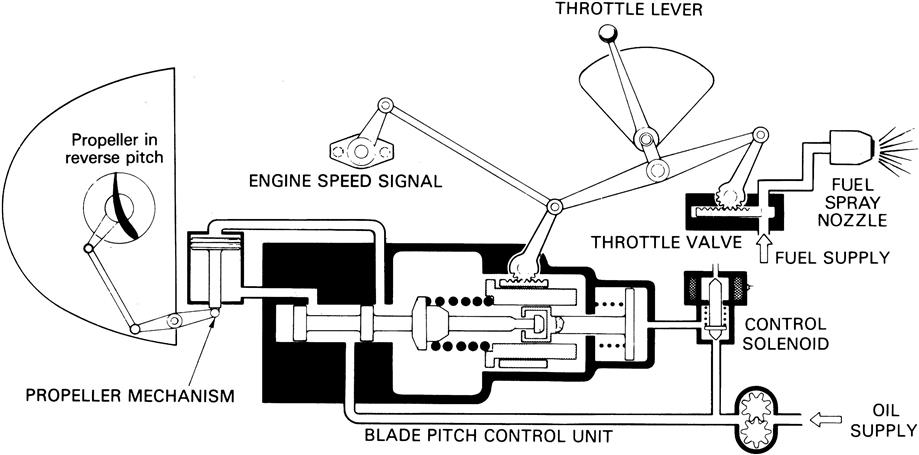
Several safety factors are incorporated in the propeller control system for use in the event of propeller malfunction, and these devices are usually hydro-mechanical pitch locking devices or stops.
Construction and Materials
The clamshell and bucket target doors (Figure 8–38) described earlier form part of the jet pipe. The reverser casing is connected to the aircraft structure or directly to the engine. The casing supports the two reverser doors, the operating mechanism and, in the case of the clamshell door system, the outlet ducts that contain the cascade vanes. The angle and area of the gas stream are controlled by the number of vanes in each outlet duct.
The clamshell and bucket target doors lie flush with the casing during forward thrust operation and are hinged along the center line of the jet pipe. They are, therefore, in line with the main gas load and this ensures that the minimum force is required to move the doors.
Both the clamshell door system and the bucket target system are subjected to high temperatures and to high gas loads. The components of both systems, especially the doors, are therefore constructed from heat-resisting materials and are of particularly robust construction.
The cold stream thrust reverser casing (Figure 8–39) is fitted between the low-pressure compressor casing and the cold stream final nozzle. Cascade vane assemblies are arranged in segments around the circumference of the thrust reverser casing.
Blocker doors are internally mounted and are connected by linkages to the external movable (translating) cowl, which is mounted on rollers and tracks. Because the thrust reverser is not subjected to high temperatures, the casing, blocker doors, and cowl are constructed mainly of aluminum alloys or composite materials. The cowl is double-skinned, with the space between the skins containing noise absorbent material.
Afterburning8
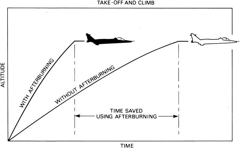
Afterburning (or reheat) is a method of augmenting the basic thrust of an engine to improve the aircraft takeoff, climb, and (for military aircraft) combat performance. The increased power could be obtained by the use of a larger engine, but as this would increase the weight, frontal area, and overall fuel consumption, afterburning provides the best method of thrust augmentation for short periods.
Afterburning consists of the introduction and burning of fuel between the engine turbine and the jet pipe propelling nozzle, utilizing the unburned oxygen in the exhaust gas to support combustion (Figure 8–40). The resultant increase in the temperature of the exhaust gas gives an increased velocity of the jet leaving the propelling nozzle and therefore increases the engine thrust.
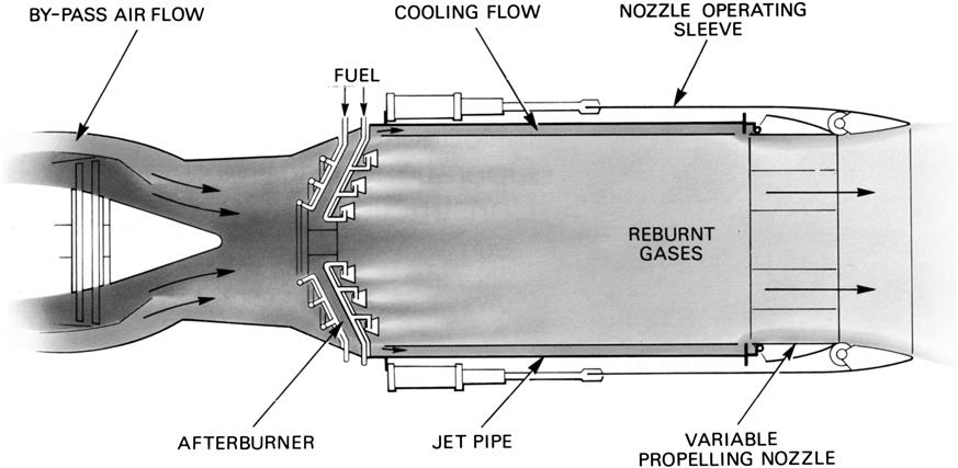
As the temperature of the afterburner flame can be in excess of 1700°C, the burners are usually arranged so that the flame is concentrated around the axis of the jet pipe. This allows a proportion of the turbine discharge gas to flow along the wall of the jet pipe and thus maintain the wall temperature at a safe value.
The area of the afterburning jet pipe is larger than a normal jet pipe would be for the same engine to obtain a reduced velocity gas stream. To provide for operation under all conditions, an afterburning jet pipe is fitted with either a two-position or a variable-area propelling nozzle (Figure 8–41). The nozzle is closed during non-afterburning operation, but when afterburning is selected the gas temperature increases and the nozzle opens to give an exit area suitable for the resultant increase in the volume of the gas stream. This prevents any increase in pressure occurring in the jet pipe that would affect the functioning of the engine and enables afterburning to be used over a wide range of engine speeds.
The thrust of an afterburning engine, without afterburning in operation, is slightly less than that of a similar engine not fitted with afterburning equipment; this is due to the added restrictions in the jet pipe. The overall weight of the powerplant is also increased because of the heavier jet pipe and afterburning equipment.
Afterburning is achieved on low by-pass engines by mixing the by-pass and turbine streams before the afterburner fuel injection and stabilizer system is reached so that the combustion takes place in the mixed exhaust stream. An alternative method is to inject the fuel and stabilize the flame in the individual by-pass and turbine streams, burning the available gases up to a common exit temperature at the final nozzle. In this method, the fuel injection is scheduled separately to the individual streams and it is normal to provide some form of interconnection between the flame stabilizers in the hot and cold streams to assist the combustion processes in the cold by-pass air.
Operation of Afterburning
The gas stream from the engine turbine enters the jet pipe at a velocity of 750–1200 feet per second, but as this velocity is far too high for a stable flame to be maintained, the flow is diffused before it enters the afterburner combustion zone, i.e., the flow velocity is reduced and the pressure is increased. However, as the speed of burning kerosene at normal mixture ratios is only a few feet per second, any fuel lit even in the diffused air stream would be blown away. A form of flame stabilizer (vapor gutter) is, therefore, located downstream of the fuel burners to provide a region in which turbulent eddies are formed to assist combustion and where the local gas velocity is further reduced to a figure at which flame stabilization occurs while combustion is in operation.
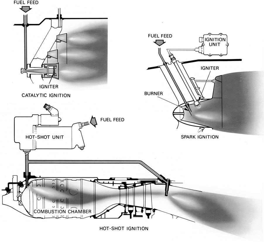
An atomized fuel spray is fed into the jet pipe through a number of burners, which are so arranged as to distribute the fuel evenly over the flame area. Combustion is then initiated by a catalytic igniter, which creates a flame as a result of the chemical reaction of the fuel/air mixture being sprayed on to a platinum-based element, by an igniter plug adjacent to the burner, or by a hot streak of flame that originates in the engine combustion chamber (Figure 8–42); this latter method is known as “hot-shot” ignition. Once combustion is initiated, the gas temperature increases and the expanding gases accelerate through the enlarged area propelling nozzle to provide the additional thrust.
In view of the high temperature of the gases entering the jet pipe from the turbine, it might be assumed that the mixture would ignite spontaneously. This is not so, for although cool flames form at temperatures up to 700°C, combustion will not take place below 800°C. If, however, the conditions were such that spontaneous ignition could be effected at sea level it is unlikely that it could be effected at altitude where the atmospheric pressure is low. The spark or flame that initiates combustion must be of such intensity that a light-up can be obtained at considerable altitudes.
For smooth functioning of the system, a stable flame that will burn steadily over a wide range of mixture strengths and gas flows is required. The mixture must also be easy to ignite under all conditions of flight and combustion must be maintained with the minimum loss of pressure.
Construction
Burners
The burner system consists of several circular concentric fuel manifolds supported by struts inside the jet pipe. Fuel is supplied to the manifolds by feed pipes in the support struts and sprayed into the flame area, between the flame stabilizers, from holes in the downstream edge of the manifolds. The flame stabilizers are blunt nosed V-section annular rings located downstream of the fuel burners. An alternative system includes an additional segmented fuel manifold mounted within the flame stabilizers. The typical burner and flame stabilizer shown in Figure 8–43 is based on the latter system.

Jet Pipe
The afterburning jet pipe is made from a heat-resistant nickel alloy and requires more insulation than the normal jet pipe to prevent the heat of combustion being transferred to the aircraft structure. The jet pipe may be of a double skin construction with the outer skin carrying the flight loads and the inner skin the thermal stresses; a flow of cooling air is often induced between the inner and outer skins. Provision is also made to accommodate expansion and contraction, and to prevent gas leaks at the jet pipe joints.
A circular heatshield of similar material to the jet pipe is often fitted to the inner wall of the jet pipe to improve cooling at the rear of the burner section. The heatshield comprises a number of bands, linked by cooling corrugations, to form a single skin. The rear of the heatshield is a series of overlapping “tiles” riveted to the surrounding skin (Figure 8–43). The shield also prevents combustion instability from creating excessive noise and vibration, which in turn would cause rapid physical deterioration of the afterburner equipment.
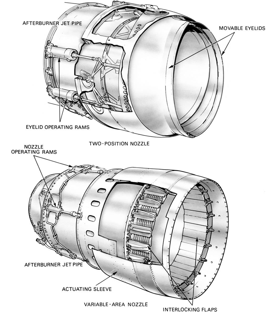
Propelling Nozzle
The propelling nozzle is of similar material and construction as the jet pipe, to which it is secured as a separate assembly. A two-position propelling nozzle has two movable eyelids that are operated by actuators, or pneumatic rams, to give an open or closed position. A variable-area propelling nozzle has a ring of interlocking flaps that are hinged to the outer casing and may be enclosed by an outer shroud. The flaps are actuated by powered rams to the closed position and by gas loads to the intermediate or the open positions; control of the flap position is by a control unit and a pump provides the power to the rams.
Control System
It is apparent that two functions, fuel flow and propelling nozzle area, must be coordinated for satisfactory operation of the afterburner system. These functions are related by making the nozzle area dependent upon the fuel flow at the burners or vice-versa. The pilot controls the afterburner fuel flow or the nozzle area in conjunction with a compressor delivery/jet pipe pressure sensing device (a pressure ratio control unit). When the afterburner fuel flow is increased, the nozzle area increases; when the afterburner fuel flow decreases, the nozzle area is reduced. The pressure ratio control unit ensures the pressure ratio across the turbine remains unchanged and that the engine is unaffected by the operation of afterburning, regardless of the nozzle area and fuel flow.
Since large fuel flows are required for afterburning, an additional fuel pump is used. This pump is usually of the centrifugal flow or gear type and is energized automatically when afterburning is selected. The system is fully automatic and incorporates “fail safe” features in the event of an afterburner malfunction. The interconnection between the control system and afterburner jet pipe is shown diagrammatically in Figure 8–44.
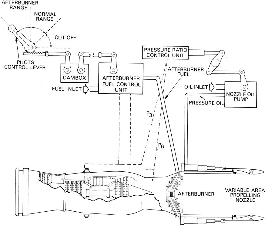
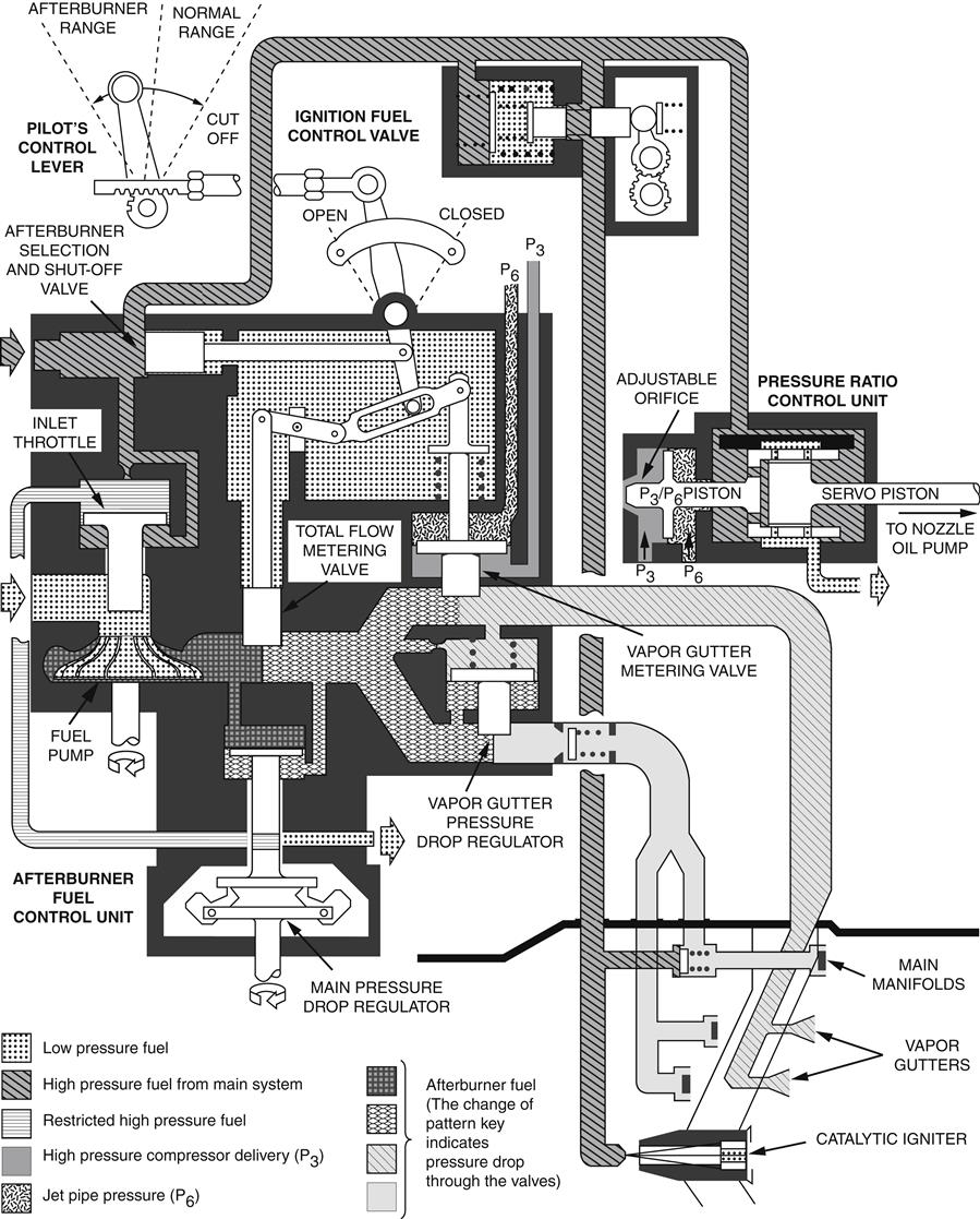
When afterburning is selected, a signal is relayed to the afterburner fuel control unit. The unit determines the total fuel delivery of the pump and controls the distribution of fuel flow to the burner assembly. Fuel from the burners is ignited, resulting in an increase in jet pipe pressure (P6). This alters the pressure ratio across the turbine (P3/P6), and the exit area of the jet pipe nozzle is automatically increased until the correct P3/P6 ratio has been restored. With a further increase in the degree of afterburning, the nozzle area is progressively increased to maintain a satisfactory P3/P6 ratio. Figure 8–45 illustrates a typical afterburner fuel control system.
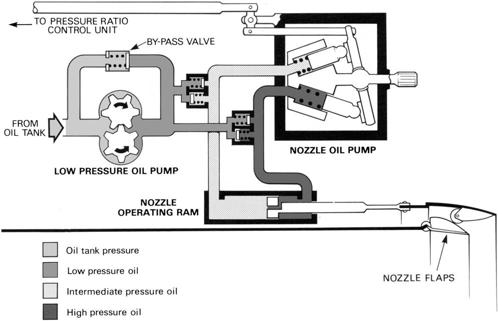
To operate the propelling nozzle against the large “drag” loads imposed by the gas stream, a pump and either hydraulically or pneumatically operated rams are incorporated in the control system. The system shown in Figure 8–46 uses oil as the hydraulic medium, but some systems use fuel. Nozzle movement is achieved by the hydraulic operating rams that are pressurized by an oil pump, pump output being controlled by a linkage from the pressure ratio control unit. When an increase in afterburning is selected, the afterburner fuel control unit schedules an increase in fuel pump output. The jet pipe pressure (P6) increases, altering the pressure ratio across the turbine (P3/P6). The pressure ratio control unit alters oil pump output, causing an out-of-balance condition between the hydraulic ram load and the gas load on the nozzle flaps. The gas load opens the nozzle to increase its exit area and, as the nozzle opens, the increase in nozzle area restores the P3/P6 ratio and the pressure ratio control unit alters oil pump output until balance is restored between the hydraulic rams and the gas loading on the nozzle flaps.
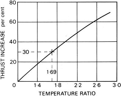
Thrust Increase
The increase in thrust due to afterburning depends solely upon the ratio of the absolute jet pipe temperatures before and after the extra fuel is burned. For example, neglecting small losses due to the afterburner equipment and gas flow momentum changes, the thrust increase may be calculated as follows.
Assuming a gas temperature before afterburning of 640°C (913°K) and with afterburning of 1269°C (1542°K), then the temperature ratio = 1542/913 = 1.69. The velocity of the jet stream increases as the square root of the temperature ratio. Therefore, the jet velocity = √1.69 = 1.3. Thus, the jet stream velocity is increased by 30%, and the increase in static thrust, in this instance, is also 30% (Figure 8–47).
Static thrust increases of up to 70% are obtainable from low by-pass engines fitted with afterburning equipment and, at high forward speeds, several times this amount of thrust boost can be obtained. High thrust boosts can be achieved on low by-pass engines because of the large amount of oxygen in the exhaust gas stream and the low initial temperature of the exhaust gases.
It is not possible to go on increasing the amount of fuel that is burned in the jet pipe so that all the available oxygen is used because the jet pipe would not withstand the high temperatures that would be incurred and complete combustion cannot be assured.
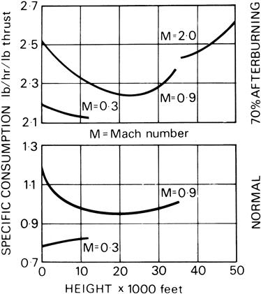
Fuel Consumption
Afterburning always incurs an increase in specific fuel consumption and is, therefore, generally limited to periods of short duration. Additional fuel must be added to the gas stream to obtain the required temperature ratio. Since the temperature rise does not occur at the peak of compression, the fuel is not burned as efficiently as in the engine combustion chamber and a higher specific fuel consumption must result. For example, assuming a specific fuel consumption without afterburning of 1.15 lb./hr./lb. thrust at sea level and a speed of Mach 0.9 as shown in Figure 8–48, then with 70% afterburning under the same conditions of flight, the consumption will be increased to approximately 2.53 lb./hr./lb. thrust. With an increase in height to 35,000 feet this latter figure of 2.53 lb./hr./lb. thrust will fall slightly to about 2.34 lb./hr./lb. thrust due to the reduced intake temperature. When this additional fuel consumption is combined with the improved rate of takeoff and climb (Figure 8–49), it is found that the amount of fuel required to reduce the time taken to reach operation height is not excessive.
Vertical/Short Takeoff and Landing9
Vertical takeoff and landing (VTOL) or short takeoff and landing (STOL) are desirable characteristics for any type of aircraft, provided that the normal flight performance characteristics, including payload/range, are not unreasonably impaired. Until the introduction of the gas turbine engine, with its high power/weight ratio, the only powered lift system capable of VTOL was the low disc loading rotor, as on the helicopter.
Early in 1941, the late Dr A.A. Griffiths, the then Chief Scientist at Rolls Royce, envisaged the use of the jet engine as a powered lift system. However, it was not until 1947 that a lightweight jet engine, designed by Rolls Royce for missile propulsion, existed and had a high enough thrust/weight ratio for the first pure lift-jet engine to be developed from it.
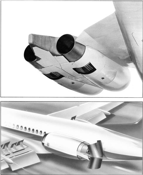
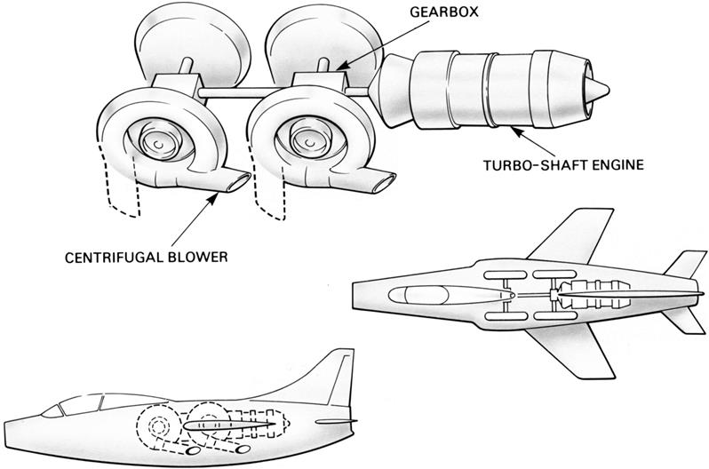
In 1956 the Bristol Aero-Engine Company was approached by Monsieur Michel Wibault with a proposal to use a turboshaft engine and a reduction gearbox to drive four centrifugal compressors that would be situated two on each side of the aircraft. The casing of these compressors could be rotated to change direction of the thrust (Figure 8–50). The concept incorporated two original ideas, i.e., the ability to deflect the thrust over the complete range of angles from the position for normal flight to that for vertical lift and a system where the resultant thrust always acted near to the center of gravity of the aircraft.
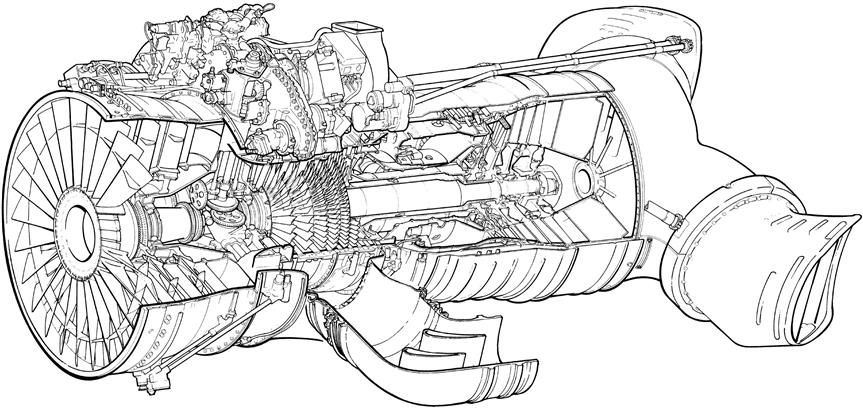
The principle proposed by M. Wibault was developed by using a pure jet engine with a free power turbine to drive an axial flow fan that exhausted into a pair of swiveling nozzles, one on each side of the aircraft. A further development was to use the fan to supercharge the engine, exhausting the by-pass air through one pair of swiveling nozzles and adding a second pair of swiveling nozzles to the exhaust system from the engine turbine. In this way the first ducted fan lift/propulsion engine (the Pegasus) evolved (Figure 8–51).
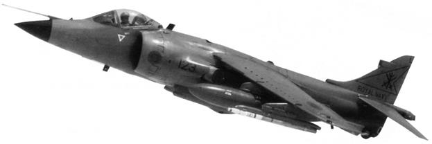
Subsequent experience with the Pegasus engine in the Harrier V/STOL fighter aircraft (Figure 8–52) led to the development of the short takeoff and vertical landing (STOVL) operational technique. In this way the additional lift generated by the aircraft wing, even after a short takeoff run, provided a large increase in the payload/range capability of the aircraft compared to a pure vertical takeoff. Vertical landing had several operational advantages compared to a short landing and so was maintained.
Methods of Providing Powered Lift
Although the Pegasus engine is the only V/STOL engine in operational service in the Western world there are several possible methods of providing powered lift, such as:
1. Deflecting (or vectoring) the exhaust gases and hence the thrust of the engine
2. Using specially designed engines for lift only
3. Driving a lift system, which is remote from the engine, either from the engine or by a separate power unit
5. For STOL aircraft, using bleed air from the engines to increase circulation around the wing and hence increase lift
In several of the projected V/STOL aircraft a combination of two or more of these methods has been used.
Lift/Propulsion Engines
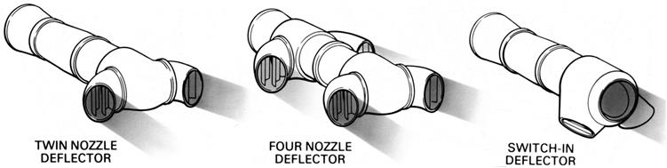
The lift/propulsion engine is capable of providing thrust for both normal wing-borne flight and for lift. This is achieved by changing the direction of the thrust either by a deflector system consisting of one, two, or four swiveling nozzles or by a device known as a switch-in deflector that redirects the exhaust gases from a rearward facing propulsion nozzle to one or two downward facing lift nozzles (Figure 8–53).
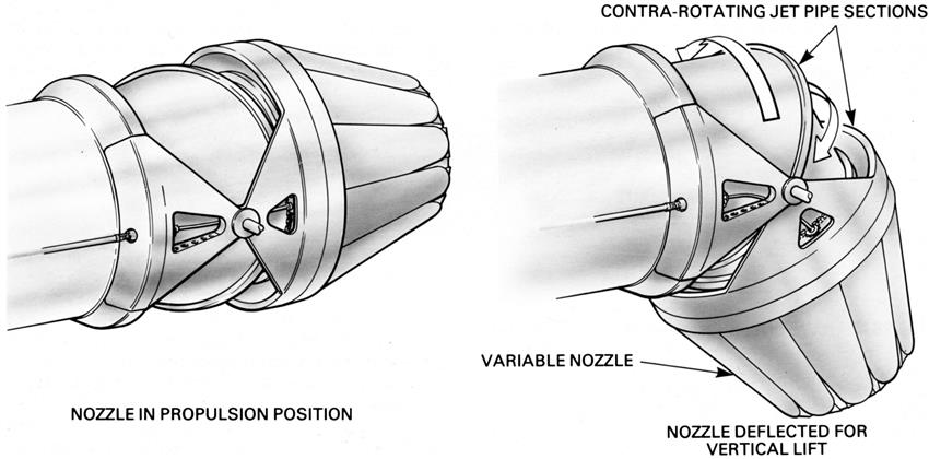
Thrust deflection on a single nozzle is accomplished by connecting together sections of the jet pipe, the joint faces of which are so angled that, when the sections are counter-rotated, the nozzle moves from the horizontal to the vertical position (Figure 8–54). To avoid either a side component of thrust or a thrust line offset from the engine axis during the movement of the nozzle it is necessary that the first joint face is perpendicular to the axis of the jet pipe. If it is desired that the nozzle does not rotate, as may be the case if it is a variable area nozzle, a third joint face that is perpendicular to the axis of the nozzle is required.
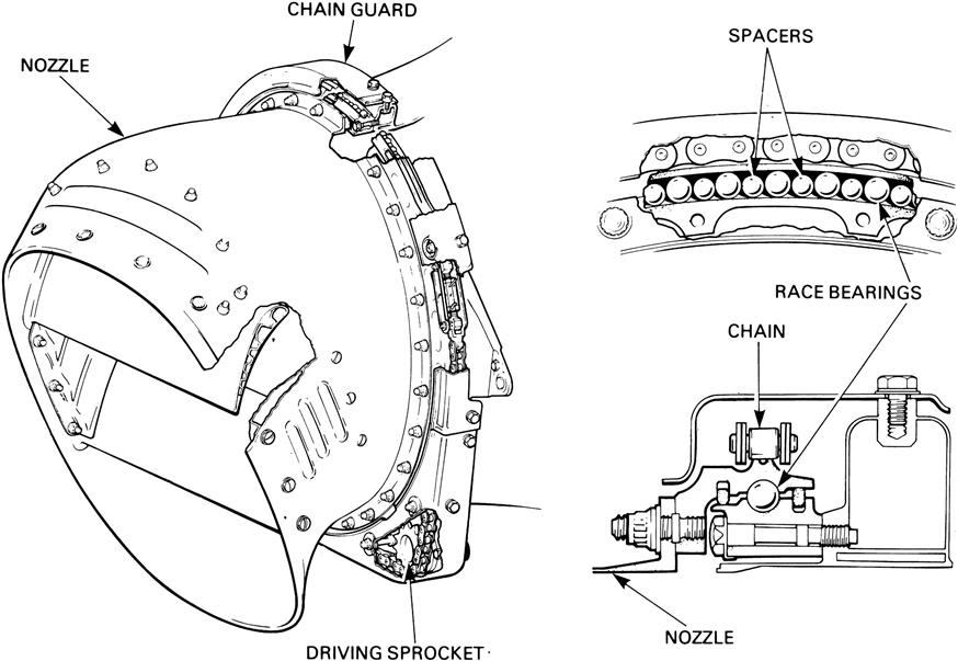
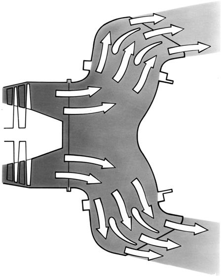
The two and four nozzle deflector systems use side mounted nozzles (Figure 8–55) that can rotate on simple bearings through an angle of well over 90° so that reverse thrust can be provided if required. A simple drive system, for example, a sprocket and chain, can be used and by mechanical connections all the nozzles can be made to deflect simultaneously. For forward flight, to avoid a high performance loss and consequent increase in fuel consumption, careful design of the exhaust unit and nozzle aerodynamic passages are essential to minimize the pressure losses due to turning the exhaust flow through two close coupled bends (Figure 8–56).
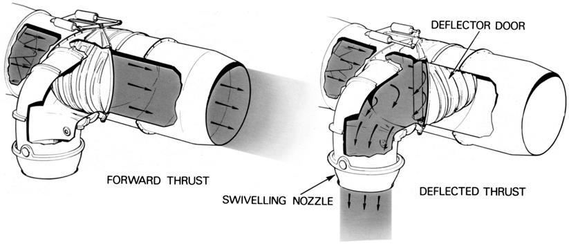
The switch-in deflector consists of one or a pair of heavily reinforced doors, which form part of the jet pipe wall when the engine is operating in the forward thrust condition. To select lift thrust, the doors are moved to blank off the conventional propelling nozzle and direct the exhaust flow into a lift nozzle (Figure 8–57). The lift nozzles may be designed so that they can be mechanically rotated to vary the angle of the thrust and permit intermediate lift/thrust positions to be selected.
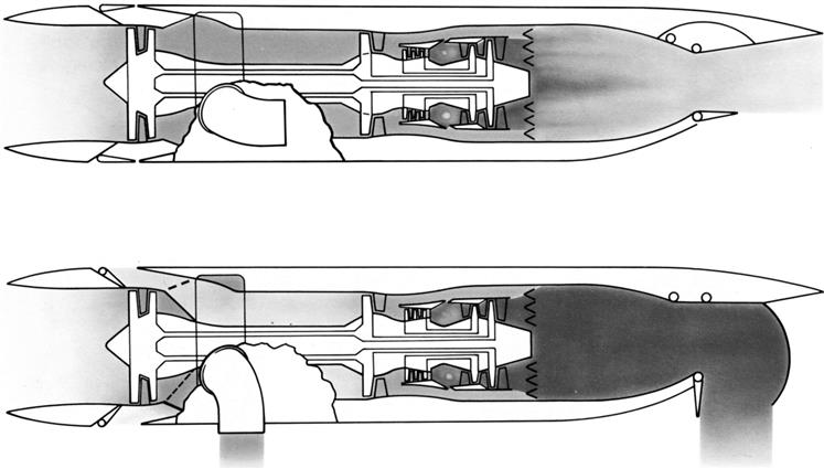
A second type of switch-in deflector system is used on the tandem fan or hybrid fan vectored thrust engine (Figure 8–58). In this case the deflector system is situated between the stages of the fan of a mixed flow turbo-fan engine. In normal flight the valve is positioned so that the engine operates in the same manner as a mixed flow turbo-fan and for lift thrust the valve is switched so that the exhaust flow from the front part of the fan exhausts through downward facing lift nozzles and a secondary inlet is opened to provide the required airflow to the rear part of the fan and the main engine. On a purely subsonic V/STOL aircraft where fuel consumption is important the valve may be dispensed with and the engine operated permanently in the latter high by-pass mode described above.
Thrust deflecting nozzles will create an upstream pressure distortion that may excite vibration of the fan or low-pressure turbine blades if the nozzle system is close to these components. Snubbers may be used on the fan blades to resist vibration. On the low-pressure turbine, shrouds at the blade tips or wire lacing may be used to achieve the same result.
Lift Engines
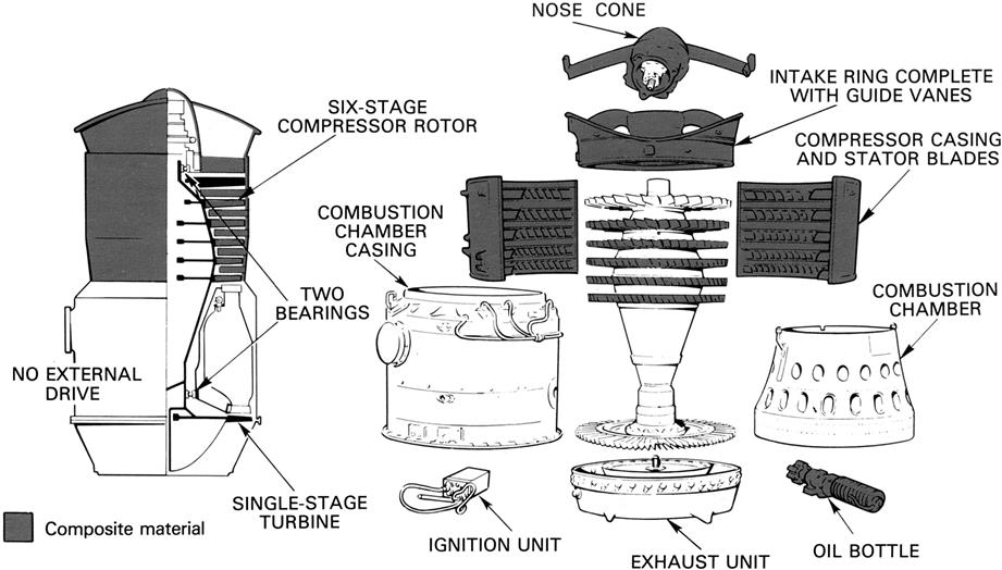
The lift engine is designed to produce vertical thrust during the takeoff and landing phases of V/STOL aircraft. Because the engine is not used in normal flight it must be light and have a small volume to avoid causing a large penalty on the aircraft. The lift engine may be a turbo-jet, which for a given thrust gives the lowest weight and volume. Should a low jet velocity be necessary a lift-fan may be employed.
Pure lift-jet engines have been developed with thrust/weight ratios of about 20:1 and still higher values are projected for the future. Weight is reduced by keeping the engine design simple and also by extensive use of composite materials (Figure 8–59). Because the engine is operated for only limited periods during specific flight conditions, i.e., during takeoff and landing, the fuel system can be simplified and a total loss oil system, in which the used lubricating oil is ejected overboard, can be used.
Lift engines can be designed to operate in the vertical or horizontal position and a thrust-deflecting nozzle fitted to provide some of the advantages of thrust vectoring. Alternatively, the engine may be mounted so that it can swivel through a large angle to provide thrust vectoring. The lift-jet engine will have an extremely hot, high velocity jet exhaust and, to reduce ground erosion by the jet, the normal exhaust nozzle may be replaced by a multi-lobe nozzle to increase the rate of mixing with the surrounding air.
The lift-fan engine is designed to reduce the jet exhaust velocity, to reduce ground erosion, and allow operation from unprepared ground surfaces. It also reduces the jet noise significantly. A range of design options have been considered for this type of engine and some are shown in Figure 8–60.

Remote Lift Systems
Direct lift remote systems duct the by-pass air or engine exhaust air to downward facing lift nozzles remote from the engine. These nozzles may be in the front fuselage of the aircraft or in the wings. The engine duct is blocked by means of a diverter similar to that described earlier.
The remote lift-fan (Figure 8–61) is mounted in the aircraft wing or fuselage, and is driven mechanically or by air or gas ducted into a tip turbine. The drive system is provided by the main propulsion power plant or by a separate engine.
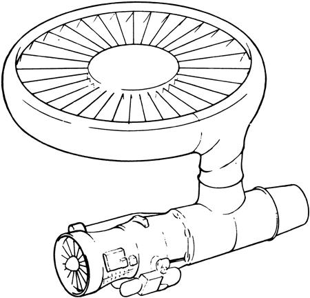
The advantage of the remote lift system is that it gives some freedom to the aircraft to position the propulsion system to the best advantage while still maintaining the resultant thrust near the aircraft center of gravity in the jet lift mode. This freedom is achieved at a cost of increased volume, particularly with the gas driven systems, due to the size of the ducts to feed the gas to the remote lift system. Although the mechanically driven remote lift-fan eliminates the need for these large gas ducts, it is done at the expense of long shafts and high power gearboxes and clutch systems.
Swiveling Engines
This method consists of having propulsion engines that can be mechanically swiveled through at least 90° to provide thrust vectoring (Figure 8–62). In addition to these propulsion engines, one or more lift engines may be installed to provide supplementary lift during the takeoff and landing phase of flight.
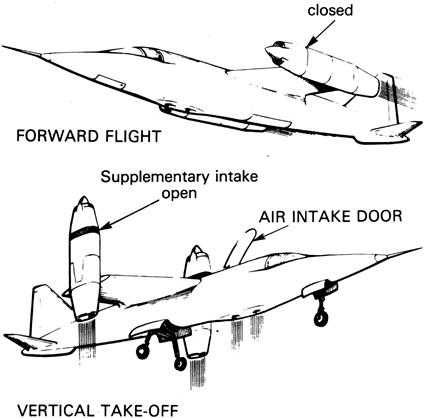
The swiveling engine system can only be used with two or more engines. This then introduces the problem of safety in the event of an engine failure. So, although there is only a small weight penalty and no increase in fuel consumption, safety considerations tend to offset these advantages compared to some of the other powered lift systems. The normal method of providing aircraft control at low speeds is by differential throttling and vectoring of the engines that simplifies the basic engine design but makes the control system more complex.
Bleed Air for STOL
Figure 8–63 shows one method how STOL can be achieved with a form of “flap blowing” The turbo-fan engine has a geared variable pitch fan and an oversized low pressure (L.P.) compressor from the exit of which air is bled and ducted to the flap system in the wing trailing edge. The variable pitch fan enables high L.P. compressor speed and thus high bleed pressure to be maintained over a wide range of thrusts. This gives excellent control at greatly different aircraft flight conditions.
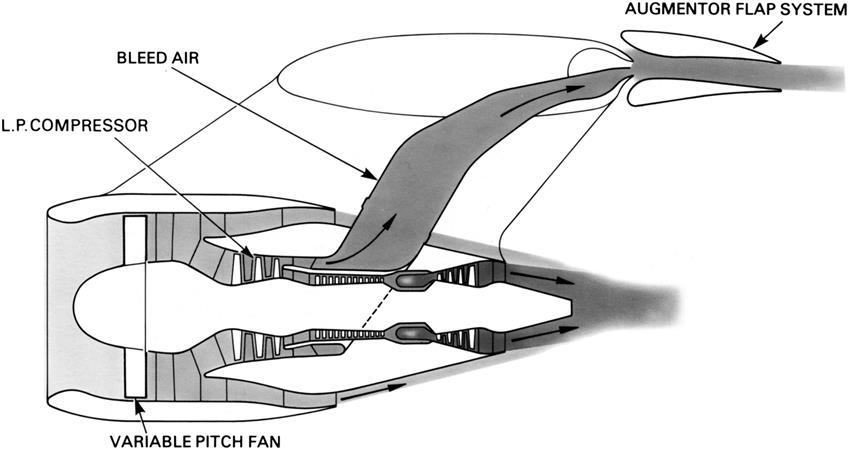
Lift Thrust Augmentation
In many cases on V/STOL aircraft augmentation of the lift thrust is necessary to avoid an engine that is oversized for normal flight with the consequent effects of higher engine weight and fuel consumption than would be the case for a conventional aircraft. This lift thrust augmentation can be achieved in a number of different ways:
Special Engine Ratings
Experience has shown that an engine rating structure can be devised that provides high thrust levels for short periods of time without reducing engine life. Operation in ground effect and the takeoff and landing maneuvers require maximum thrust for less than 15 seconds so that use of a short lift rating for that time is feasible. Figure 8–64 shows an example of thrust permissible with a 15 second short lift rating compared to that with a 2.5 minute normal lift rating.
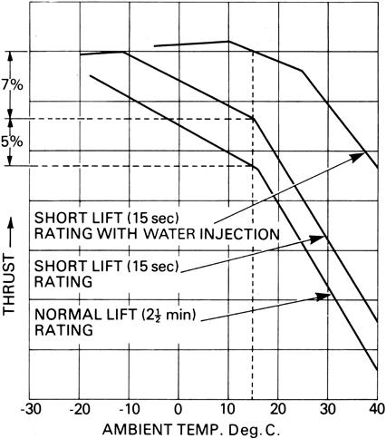
At high ambient temperatures, the engine may run into a turbine temperature limit before reaching its maximum rpm and suffer a thrust loss as a result. Restoration of the thrust can be achieved by means of water injection into the combustion chamber, which allows operation at a higher turbine gas temperature for a given turbine blade temperature. If desired, water injection can also be used to increase the thrust at low ambient temperatures.
Lift Burning Systems
The thrust of the four-nozzle lift/propulsion engine may be boosted by burning fuel in the by-pass flow in the duct or plenum chamber supplying the front nozzles. This is called plenum chamber burning (P.C.B.) (Figure 8–65) and thrust of the by-pass air may be doubled by this process. This thrust capability is available for normal flight as well as takeoff and landing and so can be used to increase maneuverability and give supersonic flight.
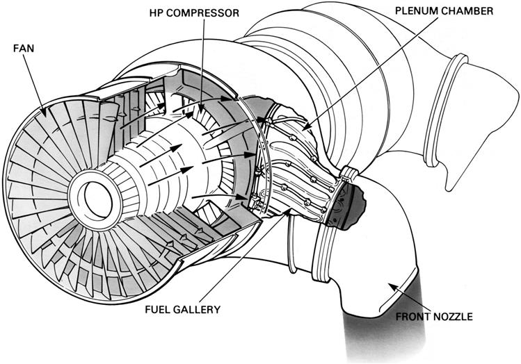
The thrust of a remote lift jet can also be augmented by burning fuel in a combustion chamber just upstream of the lift nozzle (Figure 8–66). This system is commonly known as a remote augmented lift system (R.A.L.S.). The thrust boost available from the burner reduces the amount of airflow to be supplied to it and therefore reduces the size of the ducting needed to direct the air from the engine to the remote lift nozzle.
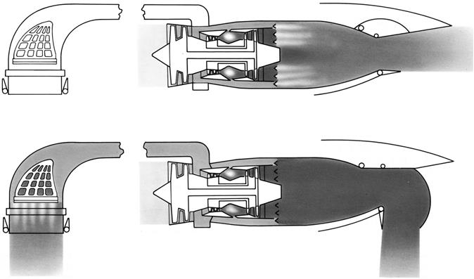
Ejectors
The principle of the ejector is that a small, high energy jet entrains large quantities of ambient air by viscous mixing and an increase in thrust over that of the high energy jet results. A number of projected V/STOL aircraft have incorporated this concept using either all the engine exhaust air or just the by-pass flow.
Aircraft Control
The low forward speeds of V/STOL aircraft during takeoff and transition do not permit the generation of adequate aerodynamic forces from the normal flight control surfaces, it is therefore necessary to provide one or more of the following additional methods of controlling pitch, roll, and yaw.
Reaction Controls
This system bleeds air from the engine and ducts it through nozzles at the four extremities of the aircraft (Figure 8–67). The air supply to the nozzles is automatically cut off when the main engine swiveling propulsion nozzles are turned for normal flight or when the lift engines are shut down. The thrust of the control nozzles is varied by changing their area that varies the amount of airflow passed.
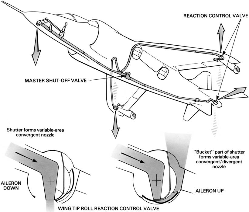
Differential Engine Throttling
This method of control is used on multi-engined aircraft with the engines positioned in a suitable configuration. A rapid response rate is essential to enable the engines to be used for aircraft stability and control. It is usually necessary to combine differential throttling with differential thrust vectoring to give aircraft control in all areas.
Automatic Control Systems
Although it is possible for the pilot to control a V/STOL aircraft manually, some form of automation can be of benefit and in particular will reduce the pilot workload. The pilot’s control column is electronically connected to a computer or stabilizer that receives signals from the control column, compares them with signals from the sensors that measure the attitude of the aircraft, and automatically adjusts the reaction controls, differential throttling, or thrust vectoring controls to maintain stability.
Thrust Distribution10
Although the principles of jet propulsion will be familiar to the reader, the distribution of the thrust forces within the engine may appear somewhat obscure. These forces are in effect gas loads resulting from the pressure and momentum changes of the gas stream reacting on the engine structure and on the rotating components. They are in some locations forward propelling forces and in others opposing or rearward forces. The amount that the sum of the forward forces exceeds the sum of the rearward forces is normally known as the rated thrust of the engine.
Distribution of the Thrust Forces
The diagram in Figure 8–68 is of a typical single-spool axial flow turbo-jet engine and illustrates where the main forward and rearward forces act. The origin of these forces is explained by following the engine working cycle shown.
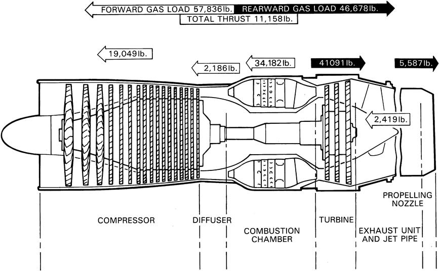
At the start of the cycle, air is induced into the engine and is compressed. The rearward accelerations through the compressor stages and the resultant pressure rise produce a large reactive force in a forward direction. On the next stage of its journey the air passes through the diffuser where it exerts a small reactive force, also in a forward direction.
From the diffuser, the air passes into the combustion chambers where it is heated, and in the consequent expansion and acceleration of the gas, large forward forces are exerted on the chamber walls.
When the expanding gases leave the combustion chambers and flow through the nozzle guide vanes they are accelerated and deflected on to the blades of the turbine. Due to the acceleration and deflection, together with the subsequent straightening of the gas flow as it enters the jet pipe, considerable “drag” results; thus the vanes and blades are subjected to large rearward forces, the magnitude of which may be seen in the diagram. As the gas flow passes through the exhaust system, small forward forces may act on the inner cone or bullet, but generally only rearward forces are produced and these are due to the “drag” of the gas flow at the propelling nozzle.
It will be seen that during the passage of the air through the engine, changes in its velocity and pressure occur. For instance, where a conversion from velocity (kinetic) energy to pressure energy is required the passages are divergent in shape, similar to that used in the compressor diffuser. Conversely, where it is required to convert the energy stored in the combustion gases to velocity, a convergent passage or nozzle, similar to that used in the turbine, is employed. Where the conversion is to velocity energy, “drag” loads or rearward forces are produced; where the conversion is to pressure energy, forward forces are produced.
Method of Calculating the Thrust Forces
The thrust forces or gas loads can be calculated for the engine, or for any flow section of the engine, provided that the areas, pressures, velocities and mass flow are known for both the inlet and outlet of the particular flow section.
The distribution of thrust forces shown in Figure 8–68 can be calculated by considering each component in turn and applying some simple calculations. The thrust produced by the engine is mainly the product of the mass of air passing through the engine and the velocity increase imparted to it (i.e., Newton’s Second Law of Motion); however, the pressure difference between the inlet to and the outlet from the particular flow section will have an effect on the overall thrust of the engine and must be included in the calculation.
To calculate the resultant thrust for a particular flow section it is necessary to calculate the total thrust at both inlet and outlet, the resultant thrust being the difference between the two values obtained.
Calculation of the thrust is achieved using the following formula:
Thrust = (A × P) + Wvj/g
where
A = area of flow section in sq. in
P = Pressure in lb. per sec.
W = Mass flow in lb. per sec.
vj = Velocity of flow in feet per sec.
g = Gravitational constant 32.2 feet per sec. per sec.
Calculating the Thrust of the Engine
When applying the above method to calculate the individual thrust loads on the various components it is assumed that the engine is static. The effect of aircraft forward speed on the engine thrust will be dealt with later. In the following calculations g is taken to be 32 for convenience. To assist in these calculations the locations concerned are illustrated by a number of small diagrams.
Thrust on Compressor Casing
To obtain the thrust on the compressor casing it is necessary to calculate the conditions at the inlet to the compressor and the conditions at the outlet from the compressor. Since the pressure and the velocity at the inlet to the compressor are zero, it is only necessary to consider the force at the outlet from the compressor. Therefore, given that the compressor
Pressure (P) = 94 lb. per sq. in. (gauge)
Velocity (vj) = 406 ft. per sec.
Mass flow (W) = 153 lb. per sec.
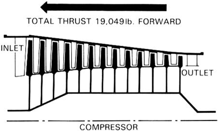
Diffuser Duct
The conditions at the diffuser duct inlet are the same as the conditions at the compressor outlet, i.e., 19,049 lb.
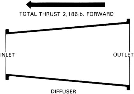
Combustion Chambers
The conditions at the combustion chamber inlet are the same as the conditions at the diffuser outlet, i.e., 21,235 lb. Therefore, given that the combustion chamber
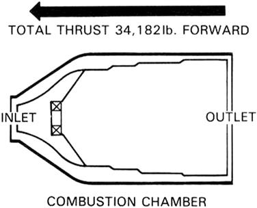
Turbine Assembly
The conditions at the turbine inlet are the same as the conditions at the combustion chamber outlet, i.e., 55,417 lb.
Therefore given that the turbine
Pressure (P) = 21 lb. per sq. in. (gauge)
Velocity (vj) = 888 ft. per sec.
Mass flow (W) = 153 lb. per sec.
This negative value means a force acting in a rearward direction.
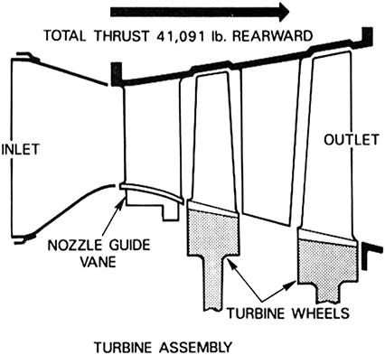
Exhaust Unit and Jet Pipe
The conditions at the inlet to the exhaust unit are the same as the conditions at the turbine outlet, i.e., ,14,326 lb.
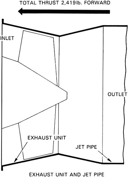
Propelling Nozzle
The conditions at the inlet to the propelling nozzle are the same as the conditions at the jet pipe outlet, i.e., 16,745 lb.
Therefore, given that the propelling nozzle
Pressure (P) = 6 lb. per sq. in. (gauge)
Velocity (vj) = 1917 ft. per sec.
Mass flow (W) = 153 lb. per sec.
= (A × P) + Wvj/g – 16,745 lb.
It is emphasized that these are basic calculations and such factors as the effect of air offtakes have been ignored.
Based on the individual calculations, the sum of the forward or positive loads is 57,836 lb., and the sum of the
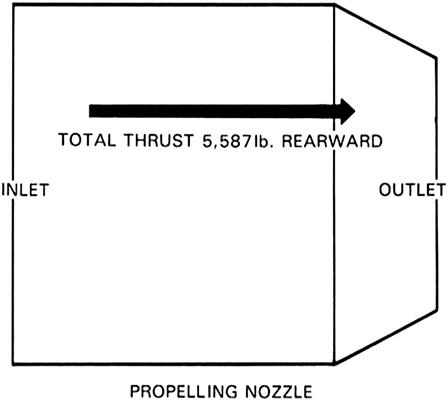
rearward or negative loads is 46,678 lb. Thus, the resultant (gross or total) thrust is 11,158 lb.
Engine
It will be of interest to calculate the thrust of the engine by considering the engine as a whole, as the resultant thrust should be equal to the sum of the individual gas loads previously calculated.
Although the momentum change of the gas stream produces most of the thrust developed by the engine (momentum thrust = Wvj/g), an additional thrust is produced when the engine operates with the propelling nozzle in a “choked” condition. This thrust results from the aerodynamic forces that are created by the gas stream and exert a pressure across the exit area of the propelling nozzle (pressure thrust). Algebraically, this force is expressed as (P – P0)A.
Therefore, assuming values of mass flow, pressure, and area to be the same as in the previous calculations, i.e.,
Area of propelling nozzle (A) = 332 sq. in.
Pressure (P) = 6 lb. per sq. in. (gauge)
Atmospheric pressure (P0) = 0 lb. per sq. in. (gauge)
Mass flow (W) = 153 lb. per sec.
Velocity (vj) = 1917 ft. per sec.
The thrust = (P – P0)A + Wvj 0
= (6 – 0) 332 + (153 × 1917)/32 – 0
= 11,158 lb., the same as previously calculated by combining the gas loads on the individual engine locations.
On engines that operate with a non-choked nozzle, the (P – P0)A function does not apply and the thrust results only from the gas stream momentum change.
Inclined Combustion Chambers
In the previous example the flow through the combustion chamber is axial; however, if the combustion chamber is inclined towards the axis of the engine, then the axial thrust will be less than for an axial flow chamber. This thrust can be obtained by multiplying the sum of the outlet thrust by the cosine of the angle (see Figure 8–69). The cosine = base/hypotenuse and for a given angle is obtained by consulting a table of cosines. It should be emphasized that if the inlet and outlet are at different angles to the engine axis, it is necessary to multiply the inlet and outlet thrusts separately by the cosine of their respective angles.
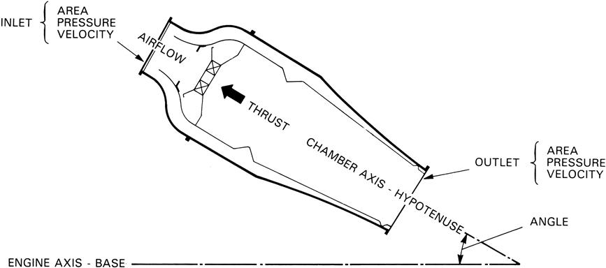
Thrust due to Afterburning
When the engine is fitted with an afterburner, the gases passing through the exhaust system are reheated to provide additional thrust. The effect of afterburning is to increase the volume of the exhaust gases, thus producing a higher exit velocity at the propelling nozzle.
Assuming that an afterburner jet pipe and propelling nozzle are fitted to the engine used in the previous calculations, and the new conditions at the propelling nozzle are as follows:
Pressure (P) = 5 lb. per sq. in. (gauge)
Velocity (vj) = 2404 ft. per sec.
Mass flow (W) = 157 lb. per sec.
= (A × P) + Wvj/g – 16,745 lb.
Therefore, compared with the previous calculation for a propelling nozzle, it will be seen that the negative thrust is reduced from –5587 lb. to –2676 lb.; the overall positive
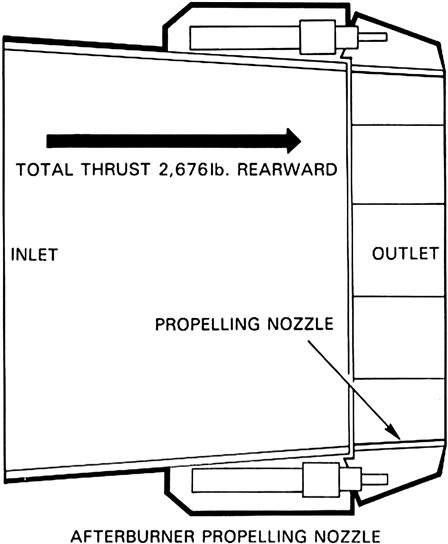
thrust is thus increased by 2911 lb., which is equivalent to a thrust increase of more than 25%.
To arrive at the total thrust of the engine with afterburning the calculations should use the above figures.
Systems Unique to Land or Marine Applications
Generators11
Standard Design
The modular design of the turbogenerator permits the selection of a standard version with either an open or closed cooling system and static or brushless excitation systems.
The generators satisfy the requirement of IEC-34 and other relevant standards such as SEN, ANSI, NEMA, CSA, etc. This means that the generators can be used in countries in which these or comparable standards apply. Generators can be custom built to satisfy other standards.
Configuration
The turbogenerators are two-pole, air-cooled synchronous generators with cylindrical rotor and direct air-cooled rotor winding. They are intended for both basic and peak-load operations and designed to withstand high short-circuiting stresses. The configuration with journal bearings in the end shields permits delivery of the machines as a single unit, which considerably simplifies installation and commissioning (see Figure 8–70).
Degrees of Protection and Methods of Cooling
The design of the generators provides for the following degrees of protection and methods of cooling in accordance with IEC 34-5 and 34-6, 1983.
| Degrees of Protection | Descriptions |
| IP 21 | Protection against contact with live or moving parts inside the machine and drip-proof. |
| IP 54 | Dust-proof, splash-proof. |
| Methods of Cooling | Descriptions |
| IC 01 | The cooling air is supplied to the machine through a screen-protected opening for different types of air filters on the long sides of the stator and is exhausted through a flanged opening. This is located at the middle of the generator housing and can be connected to a hood for the exhaust air. The method of cooling is then IC 21. |
| IC 71 | The cooling air circulates in a closed circuit and is cooled in turn by a water-cooled heat exchanger. |
These combinations of degrees of protection and methods of cooling are standard for this information source.
The different cooling methods require two fans mounted on the generator rotor.
The use of the IC 01 and IC 21 methods of cooling presupposes that the cooling air supplied is cleaned by thorough filtration. For this reason, IC 01 and IC 21 should be avoided when the cooling air available contains corrosive gases or large quantities of other pollution.
Configuration/Arrangement Forms
The machines can be supplied in the following versions:
| Arrangement Forms | Descriptions |
| IM 1005 | Horizontal shaft, two bearings mounted in the bearing end shields, one free shaft extension end with coupling flange. |
| IM 1007 | Horizontal shaft, two bearings mounted in the bearing end shields, two free shaft extensions with one coupling flange. This version permits powering of the generator from two directions. The stator is, in both cases, intended for foot mounting. If required, for example with an elevated turbine centerline, the above machines can be delivered with a base frame. |
Excitation System
The generators can be delivered with one of two alternative excitation systems:
1. Rotary brushless excitation system. The winding of the generator rotor is supplied via a rectifier mounted on the shaft, from a directly connected three-phase AC exciter. The system includes a pilot AC exciter.
2. Static excitation system. This system consists of a static thyristor rectifier unit supplied from an external power source. The excitation current is connected to the rotor windings via conventional sliprings. The static thyristor rectifier unit can be supplied on request.
Accessories
The following accessories can be supplied on request:
The following information and requirements should be provided by the end user to the OEM with any request for a bid:
• Relevant standards and recommendations
• Temperature of the cooling medium
• Power factor with rated power
• Rated voltage and voltage range
• Rated main power supply frequency
• Rated rotational speed and overspeed
• Rotation direction (as seen from the exciter end)
• Generator power in relation to the maximum and minimum ambient temperatures
• Degree of protection and method of cooling
• Cooling air quality (for methods of cooling IC 01 and IC 21)
• Cooling water quality (for method of cooling IC 71)
Technical Data on Typical Available Generators
Design Description
Stator Frame
The stator frame is of welded steel construction (see Figure 8–71).
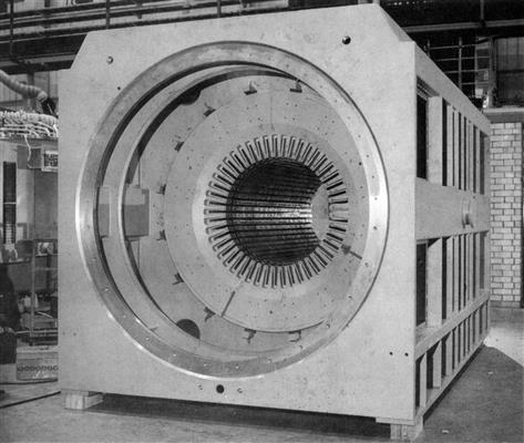
The side plates are dimensioned to bear the weight of the complete generator during lifting. Openings are provided in the top or sides for cooling air supply and exhaust. Longitudinal foot plates are provided at the bottom of the long sides of the stator frame for fixing the stator to the foundation.
Stator Core
The stator core is built up of segments stamped from thin silicon-steel sheets that give high permeability and small losses (see Figure 8–71).
The segments are varnished on both sides with a heat-resistant varnish to form an effective and permanent insulation between the sheets.
The segments are stacked to form a number of axial packages. Radial cooling air channels are formed between the packages by means of support plate segments provided with spacers.
The sheet segments are guided into place by axial guide bars. The stator core is pressed with the upper pressure ring installed to give the sheet pressure specified. The pressure ring is then locked.
The pressure rings and the superimposed pressure fingers are sprung into place during the pressing to maintain the necessary pressure in the stator core.
Stator Winding
The stator winding is a diamond winding installed in open slots with two coil sides per slot. The coils are manufactured in two halves that are brazed together.
The strands are transposed alternately through roebling in the slot section of the coil or by transposition, group by group, in the connections between the coils. The strands are insulated with impregnated glass fiber yarn.
The conductor insulation consists of MICAFOLD®.
The insulation of the coil sides is built up as continuous tape isolation, i.e., both the straight sections of the coil and the core ends are wound with tape. The insulation consists of epoxy-impregnated mica glass-tape. Both the pre-impregnated MICAREX® system and the vacuum-pressure impregnated MICAPACT® system satisfy the requirements for temperature class F (155°C). The insulation systems used are described in more detail in separate brochures.
The straight sections of the coils are fixed in the winding slots in the stator core by means of contra-wedging. Spring elements are inserted in the slots to hold the coils in the winding slots, also after long service. These exert uniform pressure on the complete length of the straight section of the coil.
The ends of the stator coils are supported against the pressure rings in the stator core by radial support plates of insulating material. The coil ends are anchored to the support plates and braced against each other. The bracing system is dimensioned to withstand the stresses that can develop during normal operations and following a sudden short-circuiting of the generator.
Stator Terminals
The connections to the busbars are located outside the generator casing (see Figure 8–72). The terminal bushings are connected to the terminal connections in the stator winding with clamps with generously dimensioned contact areas. The clamps are easily accessible for removing the stator terminals for, e.g., transport.
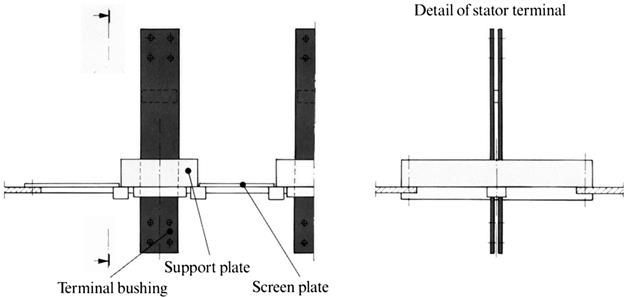
Fan Covers
The covers are manufactured of heat-resistant, glass-fiber-reinforced polyester. Each cover is divided into removable segments to simplify inspection of the coil ends.
The fan covers are mounted against the stator frame over the coil end area and lead the incoming cooling air to the axial fans on the rotor shaft.
Bearing End Shields
The bearing end shields consist of a very stiff lower half with bearing housing (see Figure 8–73). The upper half of the bearing housing is easily removed to facilitate inspection of the bearing. Holes for supply and drainage of oil are drilled in the lower half. The bearing housing is provided with connections for air extraction.

The upper half of the bearing end shield consists of a sound insulating screen plate divided into three parts to simplify removal for inspection.
Bearings
Each bearing housing contains a radial bearing (see Figure 8–74) for the generator rotor. The radial bearings are pressure-lubricated slide bearings with white-metal linings divided into staggered upper and lower segments. Lubricating oil is supplied to the bearing through drilled channels.
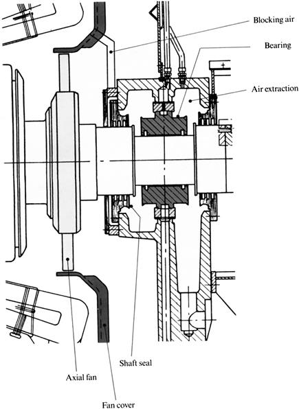
Where the bearings must take up axial forces, one is provided with axial thrust-bearing pads. The thrust bearing is double-acting, i.e., it takes up forces in both directions. One of the bearings is insulated from the bearing end shield to prevent the development of damaging bearing currents.
When the generator is to be driven from both ends, both bearings are insulated. The support bearing is always insulated. The shaft seals prevent oil leakage from the bearing housing and consist of a divided seal of oil-resistant insulation material. An air extraction system is connected to the bearing space to prevent oil leakage through the external seals. The internal shaft seals are provided with sealing caps and the intermediate space is connected to blocking air from the pressure side of the fan.
Rotor
The rotor body (see Figure 8–75) is manufactured from a cylindrical forging of high-alloy steel with suitable magnetic properties. A hole is drilled into the shaft extension for terminal conductors. The terminal conductors carry excitation current from the exciter to the rotor winding.
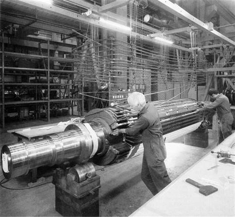
A number of axial winding slots for the excitation windings of the rotor are milled on both sides of the pole sections.
Rotor Terminals
The rotor terminals (see Figure 8–76) are located in the shaft extension and consist of two copper conductors, enclosed in a tube of insulating material and insulated from each other. The connections from the terminal conductor and radially outward to the winding consist of contact screws. The design of the contact screws eliminates the risk of fatigue failure in the connection details caused by the differential movement of the rotor winding and the shaft.
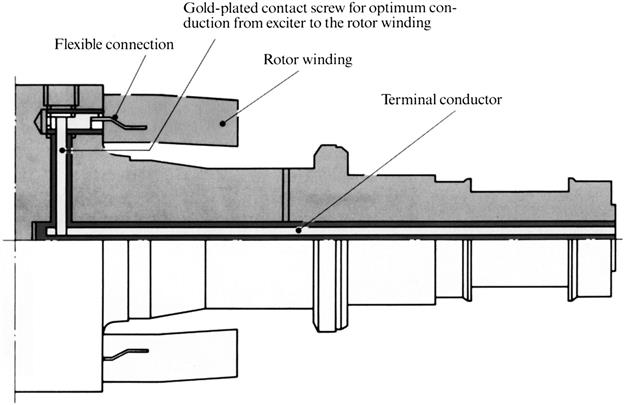
All joints are provided with gold-plated spring-contact elements to ensure effective current conduction between the contact surfaces.
Rotor Winding
The conductors in the rotor winding consist of silver-alloyed copper. Each conductor consists of two strands. The conductors are brazed to the rotor coils with silver solder.
The rotor coils are installed in the winding slots in the rotor body with conductor insulation of epoxy resin-impregnated glass fiber fabric between each conductor layer. The spaces at the side of the rotor coils function as ventilation channels.
The straight sections of the winding are supported tangentially with a number of bracing pins mounted in holes in the conductors and the coil insulation. The straight sections are fixed radially by means of pressure bars filled with synthetic resin under high pressure. The windings are thereby fixed radially and all play in the winding slots is eliminated.
The rotor coil ends are supported with blocks of glass fiber fabric laminate.
Impregnated glass fiber fabric is used as insulation between the retaining rings and rotor coil ends of the winding. The coil end insulation is provided with cooling channels after hardening.
The insulation system satisfies the requirements for temperature class F (155°C).
Rotor Retaining and Support Rings
Rotor retaining rings of high alloy non-magnetic steel are shrunk on the rotor body to provide radial support of the rotor coil ends against centrifugal forces during rotation.
The retaining ring material is not affected by stress corrosion. To ensure that the retaining rings are sufficiently stiff to remain circular, a support ring is shrunk in the outer end of the retaining ring, free from the rotor shaft.
The retaining rings and the other parts of the bracing system are dimensioned to withstand the stresses that develop with short-circuiting and overspeeding.
Axial Fan
A number of aluminum fan blades are mounted on a fan hub, shrunk on each shaft extension on the rotor. The fan blades are easily removed and replaced when the rotor is to be installed.
Balancing and Overspeed Running
The rotor is balanced when the rotor winding, insulation, and retaining rings are in place. It is then heated to a high temperature and test-run at overspeed. This results in the winding adopting its final form before the rotor is finally balanced to satisfy the relevant requirements. The normal overspeed is 120% of the rated speed. Certain of the balancing planes remain accessible when the rotor is installed in the stator.
Rotor Cooling
The rotor winding (see Figure 8–77) is directly air-cooled by ventilation channels in direct contact with the winding slots. Cooling air is drawn in between the support ring and the shaft extension by the centrifugal fan effect of the rotor.
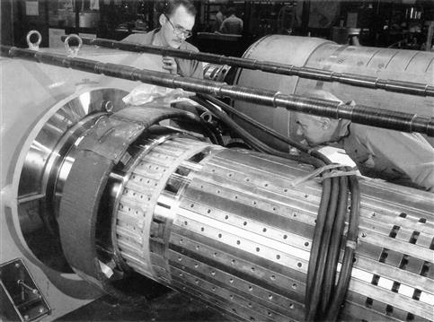
The air cooling the coil ends passes out radially through holes in the coil end insulation to the retaining ring and axially in channels under the retaining ring through holes in the support ring.
The cooling air in the winding slots is drawn in under the coil ends and into the axial cooling air channels between the sides of the slots and the conductor package. The rotor slot wedges and the beams between the winding slots are provided with a number of exhaust openings, connected in parallel, for the cooling air.
Cooling Systems
The generator is provided with two axial fans. The main task of the fans is to ventilate the stator (see Figure 8–78); the rotor itself functions as a centrifugal fan. The generator can be provided with an open or closed cooling system. The air circulation in the different cooling systems is shown in Figures 8–78 through 8–80.
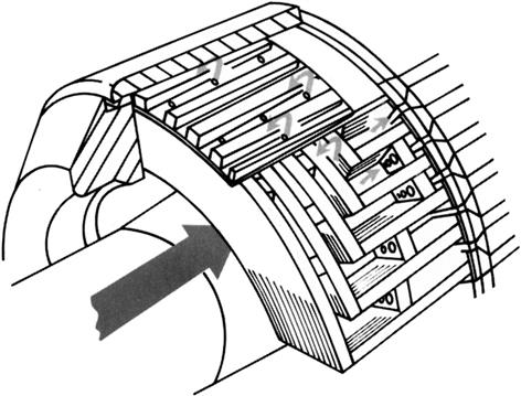

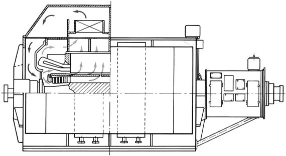
In closed cooling systems (see Figure 8–79), the cooler housings are mounted, with the air/water coolers, on the long sides of the generator. The cooler housings are welded steel constructions that lead cooling air from the coolers to the axial fans. The air/water coolers are of the lamellar tube type. The materials chosen for the tubes and water chamber are dependent on the quality of the cooling water available.
Compensation air is drawn in through a filter to replace air leakage from the machine.
With an open cooling system (see Figure 8–80), the incoming air is to be filtered.
The choice of filter is determined by the site conditions. Recommendations for filter selection are based on the information regarding the environment provided with the request to tender.
Figure 8–81 illustrates a generator assembly that has not been installed.
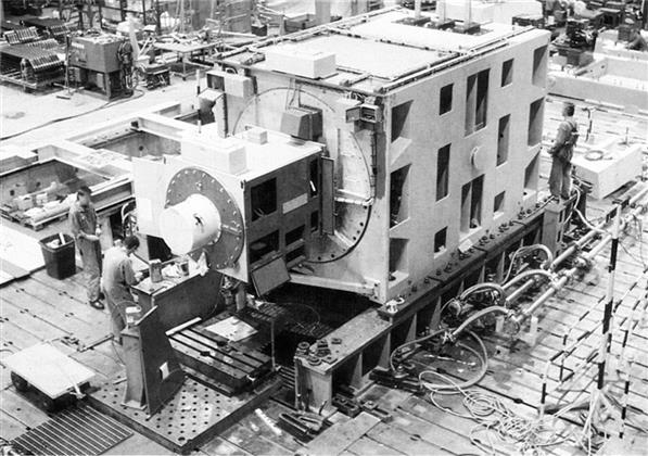
Brushless Excitation
Main Exciter
The main exciter (see Figure 8–82) is a multiple synchronous generator with salient poles in the stator.
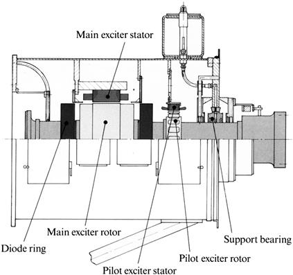
The stator and rotor winding insulation satisfies the requirements for temperature class F (155°C). The windings are impregnated for protection against damp and vibration.
Rotating Rectifier
The purpose of the rectifier is to rectify the A.C. current from the main exciter and provide the rotor winding of the turbogenerator with D.C. current via connectors in the center of the shaft.
The electrical equipment in the rectifier consists of silicon diodes and RC protection.
The rectifier is built of two steel rings that are shrunk on the shaft of the exciter rotor with intermediate mica insulation. The steel rings are connected to the terminal conductors in the center of the shaft.
All contact surfaces are specially processed to guarantee a high degree of rectifier reliability and stability during operations.
Pilot Exciter
The pilot exciter is a synchronous generator with permanent magnets on the rotor.
The rotor magnets are enclosed in a short-circuited aluminum ring that prevents demagnetization of the poles because of short-circuiting in the stator winding.
The stator winding insulation satisfies the requirements for temperature class F (155°C).
Exciter Housing
Openings are provided in the side walls of the housing for cooling air intake and exhaust and for service activities.
Support Bearing
The support bearing consists of shield, bearing insulation, bearing, and shaft seals.
The bearing, which consists of a bearing body with white metal lining, is insulated from the shield. The shaft seals against oil leakage from the bearing housing consist of a split seal of oil-resistant insulation material. An air extractor is connected to the bearing space to prevent oil leakage through the external seals. Internal shaft seals are provided with sealing caps and the intermediate space is connected to the blocking air from the pressure side of the fan.
Cooling
The exciter can be provided with either an open or a closed cooling system.
With an open cooling system, a housing with filter cassettes is mounted on one side of the exciter housing for the incoming cooling air. The cooling air exit is directed downward under the exciter housing.
With a closed cooling system, the filter housing is replaced with supply and exhaust air channels connected to the cooler housing of the generator.
Surface Treatment
In its standard version, the generator is painted with a lacquer of two-component type based on ethoxylized chlorine polymer. The generator is primed inside and outside and then finished externally in a neutral blue color. The paint is resistant to corrosive, tropical, and other aggressive atmospheres.
Static Excitation
When the rotor winding of the generator is supplied with current from a static rectifier unit, the rotor is provided with a slipring shaft and supplied via brush gear.
Slipring Shaft
The slipring shaft (see Figures 8–83 and 8–84) consists of shaft extension, insulations, sliprings, contact screws, and terminal conductors.
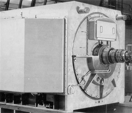
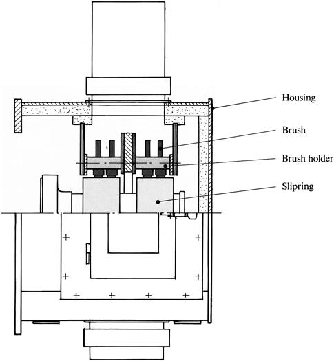
The shaft extension consists of a steel forging with flange for connection to the shaft of the generator rotor. The center of the shaft extension is drilled for the terminal conductors.
The sliprings are manufactured of steel and have generously dimensioned contact surfaces for the carbon brushes. The spiral-machined contact surface is carefully ground and polished. This prevents current concentrations and reduces brush and slipring wear. The sliprings are shrunk on the shaft extension on a cylinder of insulating material. The radial connections from the sliprings to the terminal conductors consist of insulated contact screws through holes in the shaft extension.
The terminal conductors in the slipring shaft and the rotor shaft are connected with contact screws.
Brush Gear
The brush gear consists of a frame, insulation, brackets with brush holder, and carbon brushes.
The brackets are insulated from the frame with rings of insulation material and are connected to a supply ring to which cables for the excitation current are connected. Each bracket is provided with a brush holder pocket for connection of a handle to hold two carbon brushes.
The carbon brushes in the handle parts are mounted in holders of coil-spring type that give a constant brush pressure during the service life of the brush. The handle parts are insulated and the brush holders can be removed from the brush holder pockets by hand when the brushes are to be replaced. Brush replacement is thus possible during operations.
Slipring Housing
Openings are formed in the side walls of the housing for service. These are covered with hatches provided with air filters. The opening in the end wall of the housing, towards the generator, through which the slipring shaft passes, is provided with a seal.
Inspection and Testing
General basic inspection and testing points performed during the fabrication of the generators are included in a check plan. Each manufacturing operation is subject to extensive checking.
Final Tests
Tests in accordance with Table 8–1 constitute part of the normal testing before delivery. A type test is performed on the first machine in a manufactured series and its result is used as a reference for the subsequent machines of the same type. A more extensive test can be offered separately.
TABLE 8–1
| Test | Type | Routine |
| Test | Test | |
| Overspeed test | X | X |
| Measurement of winding resistances | X | X |
| Generator characteristics | X | |
| Measurement of generator losses (through run-down test) | X | |
| Bearing vibration measurement | X | |
| Loading point with cos θ = 0 overexcited | X | |
| Heat run | X | |
| Measurement of the voltage curve form under no-load conditions | X | |
| Measurement of reactances | X | |
| Voltage test | X | X |
| Measurement of insulation resistance | X | X |
| Sound measurement | X | |
| Measurement of bearing insulation resistance | X | X |
(Source: Alstom Power.)
Control and Protection
Temperature Monitoring
A number of platinum wire resistance elements installed in different parts of the machine are used for continuous monitoring of the temperature of the parts. The connection cables of the elements are routed to junction boxes on the outside of the stator housing. The number and location of the elements are shown in the following list:
As a standard, the resistance elements have a resistance of 100 ohms at 0°C.
| Number | Location |
| 6 | In stator winding, between coil sides (2/phase) |
| 2 | Cooling air supply |
| 2 | Cooling air exhaust |
| 1 | Cooling air exhaust from exciter |
Bearing Vibration Measurement
Vibration transducers of seismic type for bearing vibration measurement can be delivered mounted on the bearing shields of the generator.
Heating Elements
Heating elements are installed in both the generator and exciter unit to prevent condensation during standstill of the generator at lower temperatures.
Current Transformers
Current transformers can be mounted on the stator terminals outside the generator casing. The transformers can be delivered in accordance with the purchaser’s requirements.
Protective Equipment
The original equipment manufacturer recommends that the generator, as a minimum, be equipped with the following protective equipment:
• Negative phase-sequence current protection
• Stator earth fault protection
• Rotor earth fault protection
• Underexcitation protection and/or underexcitation limiter
• Reverse power protection (depending on the drive machine type)
• Overexcitation and/or overexcitation limiter
• Loss-of-excitation protection; in installations where there is a risk of high overvoltages, a surge diverter is to be installed and, in certain cases, protective capacitors
Operating Characteristics
Operations with Constant Winding Temperature
With gas turbine operations, the principle described as follows is applied. This provides an optimum relation between the permitted power output of the generator and the power available from the turbine at varying cooling medium temperatures.
In accordance with international standards, particularly for gas turbine-powered generators, the generator can be loaded so that the maximum winding temperature permitted remains the same with a cooling air supply temperature other than 40°C. The winding temperature rises permit increase or decrease as much as the temperature of the cooling medium falls below, or exceeds, respectively, the values given previously.
Synchronous Compensator Operation
The generators are particularly suitable for synchronous compensator operation. To permit such operation, however, mechanical disconnection of turbine and generator is usually required and one of the main bearings must be provided with thrust bearings.
Operation at Low Ambient Temperatures
With very low temperatures the generator can be provided with a recirculation arrangement for cooling air or water.
Noise Reduction
When there are special acoustic requirements, the generator can be installed in a sound-absorbing enclosure consisting of a steel frame with panels of perforated steel sheets with sound-absorbing mineral wool in-fill.
The sealing against water leakage between the panels and the supporting structure consists of a self-adhesive rubber strip and silicon-rubber caulking.
The roof and walls of the enclosure are provided with service openings.
Base Frame
The stator frame of the generator is self-supporting and therefore requires no base frame to provide stiffness. If the center height is required to be higher than standard, the generator can be provided with a separate, welded, steel base frame.
Online Cleaning Systems12
Methods of Cleaning Fouled Gas Turbine Compressors
Offline Cleaning Methods
1. Crank soak chemical washing using in-built chemical injection water rinsing systems.
2. Crank soak chemical cleaning using handheld hose or lance.
3. Partial hand cleaning (e.g., struts, IGVs, first stage rotor and stator blading) using chemicals, rags, brushes, and water rinse.
4. Full hand cleaning with compressor covers removed using chemicals, various types of abrasives, or even light shotblasting techniques.
Online Cleaning Methods
1. Injection of abrasives (e.g., crushed nutshells) into the compressor air stream to displace blade deposits by high velocity impingement.
2. Injection of plain water to remove water-soluble deposits.
3. Injection of special chemical solutions (solvent and aqueous based) to chemically dissolve and remove surface deposits from the blades.
However, with the popular resurgence of the gas turbine as an industrial prime mover over the past decades, serious interest in the problem of lost performance and increased fuel consumption caused by fouling has led to the development of so-called “online” or “fired-wash” compressor cleaning systems. The objective of these systems being to chemically clean the compressor while the engine remains in operation at up to full speed and load in order to extend the output for longer and avoid increase in heat rate and subsequent increases in fuel consumption.
In reality, the number of companies and individuals that have been seriously involved in the development of fired-wash systems over the years are few and far between. However, since the process has, of late, gained the official blessing of some major gas turbine manufacturers, there has been a sudden proliferation of system suppliers and even more running-wash chemical suppliers who, in many cases, may have scant knowledge or experience of the fired-wash process and gas turbines to which it is being applied.
If done properly, fired-washing can be a very safe and successful method of keeping gas turbines running more efficiently. The process is being constantly improved and perfected and is, without doubt, here to stay as more and more gas turbine manufacturers offer running-wash systems as a standard fit or recommended option. However, it can also be a dangerous process if injection systems or chemicals are incorrectly designed, fitted, or used and operators should be cautious when selecting any online cleaning system.
Questions to Ask When Selecting an Online Cleaning System
About the Injection System
• How long has the vendor been in business?
• Is there an installation reference list?
• Is the system known to the engine manufacturers? Do they approve it or have no objection to its installation and use?
• Is the system a recommended option or installed as standard in new gas turbines by any manufacturers/packagers?
• Does the vendor design, manufacture, install, service and guarantee the system himself? (If not, why not?)
• Are the materials of the system of good quality?
• How long does the vendor say it should take to install the system? Some can take a few hours to install, others can take weeks to install if it involves drilling thick casting, etc.?
• Is the design safe? Could it possibly damage the engine or injure those using it?
Since online washing has rather suddenly come into vogue even though deep routed knowledge and experience of the process is known to relatively few system suppliers and operators it is hoped that this section will be of sound practical help to those operators who would like to adopt online chemical washing procedures but who are unfamiliar with the concept.
Questions to Ask When Selecting an Online Cleaning System about the Cleaning Chemical(s)
• Does the vendor also manufacture special chemicals for use with the system and are they tried, tested, and approved?
• Was the chemical on offer solely developed for online cleaning or was it originally developed for some other application not connected with gas turbines?
• Does the vendor offer a choice of chemicals (i.e., solvent-based and water-based) to suit particular fouling and/or environmental requirements?
• Is the chemical supplied as a concentrate to save storage and transportation costs? Paying for water in ready-to-use chemical solutions can be very expensive and unnecessary.
• Can the chemical offered also be used safely and effectively for offline compressor washing if need be?
• Does the vendor offer ex-warehouse availability of chemicals?
• If the vendor only supplies chemicals, are you sure it is safe to use them in your injection system?
Recommendation: Be very wary of using any chemical especially for online fired-washing, unless it has been properly tested and approved and has a good long-term safety record behind it.
Can Online Washing Really Be Cost Effective and Is It Really Necessary—or Just Another Fad?
Due to the current Middle East crisis the cost of fuel has increased by roughly 70% over the past 3 months. For example, No. 2 diesel was, as of October 1, 1990, being quoted on the Rotterdam market at $300/ton whereas 3 months prior it was priced in the region of $180/ton.
Even if the fuel drops back to pre-crisis levels, in due time the fuel costs for operating any gas turbine are still substantial even when the machine is kept in perfect operating condition and at peak efficiency. A fouled compressor can easily increase fuel consumption by 5% or more and, in real terms, a 5% increase for the operator of a typical 25 MW heavy industrial unit running base load for say 8000 hours per year would add over $0.5 million/year to the fuel bill at pre-Gulf crisis fuel prices and close to $1 million extra at current prices.
Advantages and Disadvantages of Offline Compressor Washing
Advantages
Disadvantages
• Gas turbine must be shut down completely
• Costly problems in disposing of waste chemical and rinse water
• Lost power output cannot be recovered
• Increased fuel consumption cannot be recovered
• Shutdown/startup thermal cycles for offline wash are damaging
• Extra wear and tear on starting system during offline wash
• Can wash salt and corrosives into inaccessible parts of the engine
• Only a short-time cure and not a prevention for compressor fouling
This should be more than sufficient incentive for any turbine operator to at least investigate the potential benefits of online washing to control compressor fouling when the machine is running because the alternative of offline crank-soak washing can only be a temporary cure and not a prevention of the fouling and performance loss that only takes place when the machine is running. Lost performance is precisely that—lost!
Increased fuel consumption is, of course, only part of the story of compressor fouling, and loss of power output can be an even greater cost penalty if available power is directly related to production; such as in the case of an offshore oil production facility. In that instance loss of power can equate directly with loss of production and revenue. Similarly, co-generation facilities that sell excess energy to guarantee profitable survival can find themselves with major problems if projected amounts of saleable excess power are reduced due to performance loss and/or total shutdown to perform offline washing to restore lost performance.
The actual cleaning efficiency of the system is wholly dependent on both the method of injection and the cleaning solution but at the least one should expect to reduce by 50% the degradation that would otherwise be caused by compressor fouling.
If that were extrapolated out in the case of our typical 25 MW/8000 hour/year base load machine the additional extra fuel bill for every 1% increase in fuel burn would be about $110,000 (or $180,000 at present crisis price level). If the online washing process prevented even a minimal 50% of this extra fuel burn (a $55,000 or $90,000 saving) then the annual cost of cleaning chemical ($8000 to $16,000) would be well covered in addition to the capital cost of the system also being recovered from savings within the first 6 months.
Why Not Try to Avoid Fouling Altogether Instead of Spending Time and Money on Compressor Washing Techniques?
The simple answer—at least at this time—is that it is virtually impossible even with the finest multi-stage, high efficiency filtration systems to completely avoid compressor fouling.
There are many sources of compressor fouling but the worst and the most common is the ingestion of oily vapors that can readily pass through filtration systems.
Typical Causes of Gas Turbine Compressor Fouling
• Passage of oily vapors through filtration system
• Ingestion of oily vapors through breaches in air inlet plenum
• Leakage of oil from oil-bath type filtration systems
• Passage of very fine particulate matter through breaches in plenum
• Reingestion of exhaust gases through filtration system and breaches in air inlet plenum casing
• Ingestion of saturated salt droplets or salt crystals through filters and/or breaches in plenum casings
• Ingestion of seasonal tree and plant gums
• Ingestion of wide variety of chemicals and other pollutants generated at the site of gas turbine operation
Typically these oily vapors are the catalyst to compressor fouling in most cases. After restarting the gas turbine with a clean, dry compressor, a film of oily/greasy deposit can build up rapidly on the compressor airfoils (roughly in the first third of the compressor) and this forms a perfect “flytrap” to catch and absorb dry particulate matter that would otherwise have passed harmlessly through the compressor.
In more than 10 years of designing and developing compressor cleaning systems the writer has observed that classic fouling—particularly in polluted industrial environments—is basically a three-phase affair.
Firstly, there is the laying down of the oily film and the rapid absorption and entrapment of dry particulates. This can occur within days or even hours after restarting a cleaned engine and there can be a substantial reduction in output in a relatively short period of time.
Next, there is a slowing down of performance loss as the surface deposit gradually dries and the rate of fouling decreases.
Finally, there is a relatively long phase of slow decline over a period of weeks or even months followed by a further sharp decline as the aerodynamic tolerance of the compressor decreases and/or the surface deposit once more becomes sticky with more oily residues.
A fingernail scratch into the apparent dry, carbonaceous surface deposit on the bell mouth struts of many a compressor is almost sure to reveal the initial oily substrate that was laid down shortly after the cleaned engine was put back into service.
In general, one could say with confidence that compressor fouling would be much diminished if all traces of oil and grease could be prevented from entering the compressor and in this regard close attention to the complete integrity of the air inlet plenum after the filters is strongly recommended since even small breaches can allow inordinately large quantities of unfiltered vapors and particulates to pass freely into the compressor.
Because it is almost impossible to prevent some degree of compressor fouling the logical approach is to try to find a way of controlling and reducing the rate of fouling and ultimately to control it to a point that it does not affect performance at all.
This means regular compressor cleaning on a sufficiently frequent basis to prevent any meaningful amounts of deposit from building up between each wash and that could mean once a day or once per week depending on operating circumstances.
Advantages and Disadvantages of Online Chemical Cleaning of Compressor
Disadvantages
• Can have limited effect if chemical is not properly formulated
• Can have limited effect if chemical is not injected correctly
• Some online cleaning chemicals are quite expensive and results may not justify the costs in some cases
• Some online cleaning systems are very expensive and are priced against what the customer may save in operation costs rather than what it actually costs to develop and manufacture the equipment
Advantages
• Can arrest or slow down the rate of compressor fouling while the gas turbine remains in operation thus maintaining heat rate and saving large amounts of money by avoiding additional fuel burn
• Helps maintain power output to avoid loss of production revenue and unnecessary use of standby machines
• There is no interruption to production or operation routines as washing can be carried out at full speed and load
• The cleaning process usually takes only a matter of minutes
• There is no waste chemical or water to deal with after the wash
• Assuming the chemical is properly formulated and injected it should not contribute to any additional atmospheric pollution
• By avoiding shutdowns for offline washing, thermal cycles are also considerably reduced thus extending life of the engine.
• No erosion, thermal shock, bearing damage, or cooling system blockage (if properly designed system is used)
It would be highly impractical and very costly to do this on a shutdown, crank-wash basis so the only practical solution is online or fired washing since this can be readily done without any interference to the normal operation of the engine.
Other Online Compressor Cleaning Methods
The question is, is online chemical washing the only online cleaning method?
The answer is no but of the other available choices it may be the most efficient, safe and practical online procedure.
The first alternative—and probably as old as the gas turbine itself—is abrasive cleaning using a variety of crushed nutshells or carbon-based pellets but in general this method is impractical for most modern gas turbines because, among other problems and drawbacks, the abrasive medium can damage coatings and plug turbine cooling holes with possible catastrophic results.
Advantages and Disadvantages of Abrasive Compressor Cleaning
Possible Advantages
Possible Disadvantages
• Blockage of blade cooling systems leading to turbine failure
• Blockage of instruments and/or control bleed air posts
• Jamming of variable guide vanes and/or stator vanes
• Removal of oily/greasy material to rear of compressor and/or into combustion system causing further performance loss
• Transfer of salt contamination from compressor to hot end and subsequent corrosion
• Ineffective against lacquered or hard carbonaceous deposits
The second alternative to online chemical cleaning is online plain water washing, which has been advocated by some as a cheap solution with the apparent simplistic argument that water must be inexpensive and chemical must be expensive.
This would, of course, be the perfect solution if all compressor fouling was water-soluble and the water used was virtually free of all dissolved and suspended solids so as to avoid corroding the engine in the process of trying to clean it.
Unfortunately, compressor fouling is rarely, if ever, of a water-soluble nature and good quality pure water is not always easy to come by. Many a gas turbine has been badly corroded by poor attention to water quality particularly when applied to a hot engine.
Water washing should not be confused with the use of so-called water-based or aqueous chemicals. Generally, water-based chemicals are formulated from various types of surfactants (surface acting agents) and corrosion inhibitors with water being in the majority (between 80 and 98% depending on the brand) carrying agent.
Some of the new formula water-based materials (some using very pure food-grade surfactants) are quite effective at breaking down stubborn oily/greasy deposits and are proving quite successful even for fired-washing but are particularly attractive for offline washing because of their high biodegradability factor, which makes the disposal of the waste chemical a lot easier.
Advantages and Disadvantages of Cleaning Compressors with Plain Water
Advantages
Disadvantages
• Not effective against oily/greasy contamination
• Not effective against lacquered or hard carbonaceous deposits
• May move deposits to hot section of engine to cause corrosion
• May directly cause corrosion if not inhibited
• May cause thermal shock/blade stress if not injected correctly
• Not effective for offline cleaning (unless deposits are water soluble)
• Must be high quality water with very low TDS and suspended solids
Expansion Joints13
An expansion joint is a device used to allow movement in a piping system while containing pressure and the medium running through it.
Frequently, thermal growth, equipment movement, vibration, or pressure pulsation can cause movement in a piping system. When flexibility for this movement cannot be designed into the piping system itself, an expansion joint is the ideal solution.
There are four basic movements that can be applied to a bellows. These are axial, lateral, angular, and torsional as illustrated below. Bellows behave like springs in a piping system. When they are compressed, they resist the movement the same as a spring would. The spring rate of a bellows is entirely dependent on bellows geometry and material properties.
• Axial movement is the change in dimensional length of the bellows from its free length in a direction parallel to its longitudinal axis.
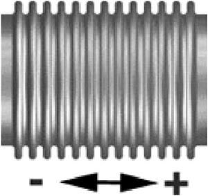
• Angular movement is the rotational displacement of the longitudinal axis of the bellows toward a point of rotation.
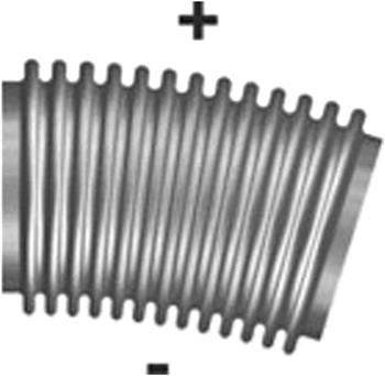
• Lateral movement is the relative displacement of one end of the bellows to the other end in a direction perpendicular to its longitudinal axis (shear).
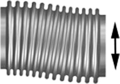
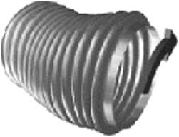
End Connections
Flanges include special flanges, slip-on, or angle flanges.
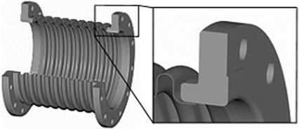
• Vanstone ends are modified flanged ends with the added flexibility of resolving bolt-hole misalignment.
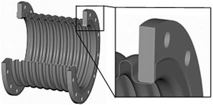
Types of Expansion Joints
Unrestrained Assemblies
• Single expansion joint assemblies are the simplest type of expansion joint consisting of a single bellows element welded to end fittings, either flange or pipe ends.
• Universal expansion joint assemblies consist of two bellows connected by a center spool piece with flange or pipe ends. The universal arrangement allows greater axial, lateral, and angular movements than a single bellows assembly.
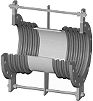
• In externally pressurized expansion joints, line pressure acts externally on the bellows by means of a pressure chamber. This allows a greater number of convolutions to be used for large axial movements, without fear of bellows instability. Externally pressurized expansion joints have the added benefit of self-draining convolutions if standing media are a concern. Anchors and guides are an essential part of a good installation.
Externally Pressurized Expansion Joints
Restrained Assemblies
• Tied single bellows assemblies add tied rods to a single bellows assembly to increase design flexibility in a piping system. The tie rods are attached to the pipe or flange with lugs that carry the pressure thrust of the system, eliminating the need for main anchors.
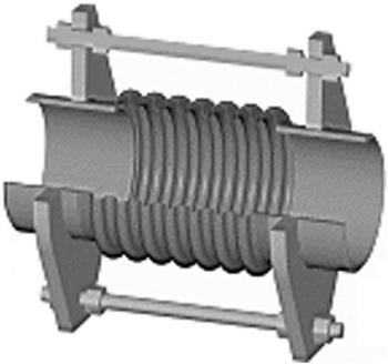
• Tied universal assemblies are similar in construction to a universal assembly except that tie rods absorb pressure thrust and limit movements to lateral offset and angulation only.
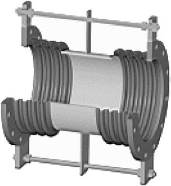
• Hinged bellows assemblies limit movement to angulation in one plane. Hinged assemblies are normally used in sets of two or three to absorb large amounts of expansion in high pressure piping systems.
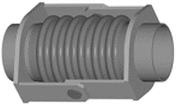
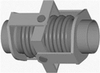
Accessories for Special Service
• Tie rods are devices, usually in the form of bars or rods, attached to the expansion joint assembly and are designed to absorb pressure loads and other extraneous forces like dead weight.
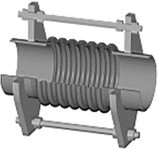
• Limit rods are used to protect the bellows from movements in excess of design that occasionally occurs due to plant malfunction or the failure of an anchor. Limit rods do not contain the pressure thrust during normal operation.
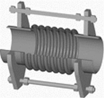
• Purge connections are used in conjunction with internal liners to lower the skin temperature of the bellows in high temperature applications such as catalytic cracker bellows.

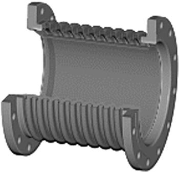
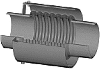
Bellows Manufacture
The bellows element is the most important component of an expansion joint. This thin-walled, corrugated membrane allows flexibility in a piping system while containing the pressure and media. When complete, each bellows has a unique working pressure, spring rate, and cycle life that are entirely dependent on its geometry and material.
Bellows are manufactured using an expanding mandrel (punch forming) method followed by a finish rolling. A rectangular sheet is sheared and rolled into a tube. The tube is welded using an auto flat-bed welder with no filler metal added. The longitudinal seam weld is then “plannished” back down to the parent material thickness. Any dye penetrant, X-ray, or air testing is performed at this time. When testing is complete, the convolutions are punched individually drawing material from the top and bottom of the tube. This drawing process eliminates any thinning in the bellows material.
At this point, the convolutions have more of a “V” shape than the final “U” shape that is required. This is easily solved with the final re-rolling of the bellows between a series of aluminum bronze rolls. After trimming the bellows attachment ends (skirts), the bellows is complete and ready to have attachment ends installed.
Shipping
Every expansion joint that leaves the factory is provided with installation instructions. These instructions describe the simple, straightforward requirements that must be followed to ensure a trouble-free installation.
Shipping Bars
These are temporary attachments that “hold” the expansion joint at its correct installed length during shipping and installation. Angle iron or channel section is used and is always painted bright yellow. Shipping bars must never be removed until after the unit has been correctly welded or bolted into the piping system. Caution: tie rods or limit rods are sometimes mistaken for shipping bars.
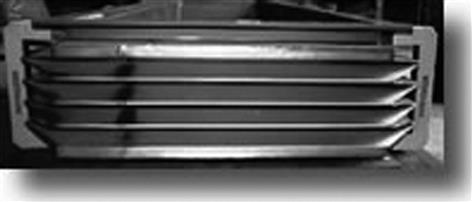
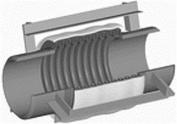
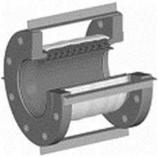
Never Tamper with These Attachments
Note: Great care must be taken when removing the shipping bars. If a welding or burning torch is used, always protect the bellows element from burn splatter with a flame-retardant cloth or other shielding material.
Installation Guidelines
Unrestrained Expansion Joints
Unrestrained expansion joints are not provided with attachments such as tie rods or hinges to restrain pressure thrust. Therefore, they can be used only in a piping system that incorporates correctly designed anchors and pipe alignment guides. These components prevent the bellows from overextension and damage due to distortion under operating conditions.
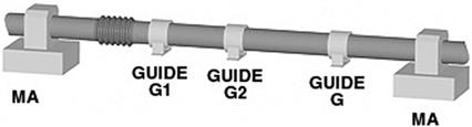
Restrained Expansion Joints
Tied expansion joints can be of the single or universal type provided with restraints such as tie rods, hinges or gimbals. Tie rods and gimbals allow the expansion joint to move in all planes. Hinges allow movement in a single plane only. These restraints are designed to absorb the pressure thrust and other external loads like pipe dead weight. For restraints to remain effective, the expansion joint can absorb only lateral offset or angulation in directional changes in the piping system, such as “Z” bends, “U” bends, or “S” bends. Tied units are used where the equipment or adjacent structures cannot accommodate pressure thrust.
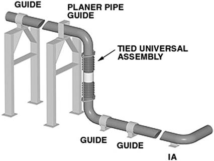

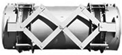
Specific Applications
Special product lines include a variety of rectangular joints, PenSeals (boiler seals), silencer bellows seals, expansion joints for fluid catalytic cracking units (FCCU), gas turbine exhaust (GTX) systems, aerospace, heat exchangers, and many other heavy industrial applications.
Expansion joints are made in both metal and fabric designs from 3˝ nominal diameter to 200˝ with process temperatures from –325–2500°F. Pressures for these designs range from full vacuum to 2000 psig. Single-ply, multi-ply, root ring, equalizer ring, and toroid bellows designs are also available.