Manufacturing, Materials, and Metallurgy
Abstract
Manufacturing methods, materials, and metallurgy (MMM) in gas turbines, like other technical elements of turbine technology, are dictated by the global business climate. This chapter describes the main elements of this climate as it affects MMM. The importance of each element at any given time depends on global economics as dictated by currencies, politics, and wars. Just 20 or so years ago, industrial gas turbine engine could mean a heavy unsophisticated engine compared to its aviation counterpart. Industrial engines are still relatively heavier (with their large flat base and sometimes a “noise protection house” around them). However, their metallurgical sophistication may be quite comparable to aeroderivative and even aviation engines. The increasing sophistication in an OEM’s F, G, and H technology is not that different from that in its aeroderivatives and flight engines.
Keywords
Manufacturing; metallurgy; creep resistance; materials; business climate; global economics
“There are old pilots, and there are bold pilots, but there are no old, bold pilots.”
—Old Pilots’ saying
Manufacturing methods,1 materials, and metallurgy (MMM) in gas turbines, like other technical elements of turbine technology, are dictated by the global business climate. The summary that follows describes the main elements of this climate as it affects MMM. The importance of each element at any given time depends on global economics as dictated by currencies (consider the Asian monetary crises of the late 1990s), politics, and wars (see also Chapter 14).
Just 30 or so years ago, industrial gas turbine engine could mean a heavy unsophisticated engine compared to its aviation counterpart. Industrial engines are still relatively heavier (with their large flat base and sometimes a “noise protection house” around them). However, their metallurgical sophistication may be quite comparable to aeroderivative and even aviation engines. The increasing sophistication in an OEM’s F, G, and H technology is not that different from that in its aeroderivatives and flight engines. Rolls Royce, for instance, has consistently used its aircraft engine metallurgical technology in its land-based models, which it calls by the same generic stem: Avon, RB211, Trent, and so forth. Siemens Westinghouse is not officially an aircraft engine manufacturer, neither are Mitsubishi Power Systems (MPS) and Alstom (although ABB Stal, which was absorbed under the Alstom umbrella in 2000, had developed the aeroderivative GT35). However, their metallurgy is every bit as sophisticated as that which their rivals, who also make aircraft engines, employ.
In today’s age of workers who can travel or change jobs internationally or get different work visas within a week, scarcely anything is sacred in design technology. The wide chord fan blade that proved such an asset to Rolls Royce aeroengine designs showed up on the GE 90 some years after its original design, with different “insides.” The example list is endless and travels in both directions across oceans.
To keep costs down, every major manufacturer in the western hemisphere contracts the manufacture of specific components to countries with low labor rates. Korea used to be a favorite, but then Singapore, Malaysia, and Thailand became hotbeds of electronic component manufacture. China and India followed, with contracts acquired for every type of component: mechanical (such as blade and vane airfoils) or electrical (such as switchgear) and electronic (controls, PLCs, PCs, and so forth). The OEMs “follow” the lowest labor rates available and train the local workforce.
The contemporary power generation industry also sees the OEMs hard at work selling, installing, and running power plants in these newly industrializing countries (NIC). Typically, they then train the local workforce to operate and eventually take over these plants, which therefore are build, own, operate, transfer (BOOT) projects. The initial “operate” phase then positions the OEM well for a “power by the hour” contract (see Chapter 12, Maintenance, Repair, and Overhaul). All this activity tends to promote the eventual transfer of repair and overhaul (R&O) functions to local repair shops. The OEM’s workforce may stay approximately the same globally: numbers that are hired in Asia and Latin America equate to layoffs in countries with higher labor costs.
The large manufacturers such as General Electric have licensees, such as GEC and Nuovo Pignone, that assemble entire engines for them. These licensees, in turn, are large enough that they may establish factories in NICs.
Acquisitions, mergers, and joint venture programs also move technology into different OEM firms. Ruston became European Gas Turbine (EGT), which developed new grassroots models, like the Cyclone, Tempest, and Typhoon that differed considerably from the old Ruston’s more traditional, conservative fare. Then EGT became part of ABB, which in 1999 became ABB Alstom, and Alstom Power in 2000. Later, Siemens bought portions of Alstom Power and its engine lines. The combined product range with respect to gas turbines is both broad and varied, the range of manufacturing methods and design development strategy even more so. Also, before this, Siemens and Westinghouse merged. Rolls Royce gained a US partner in Allison. Both Rolls and Siemens can now bid for US DOE grants along with US companies.
Reorganizations internally can shift centers of special knowledge, domestically and abroad. To conserve on overhead, Pratt and Whitney closed its West Palm Beach military engine facility and sent that workforce to join the commercial aircraft engine group in Connecticut.
One example of a joint venture gas turbine is the V2500 engine (with the three Japanese manufacturers that make up the Japanese Aeroengine consortium making the low-pressure compressor, including the wide chord bladed fan, to a Rolls Royce design). Rolls Royce designs and makes the high-pressure compressor and the oil system. Pratt and Whitney designs and makes the hot high-pressure section and MTU (Motoren Turbinen Union) designs and makes the low-pressure turbine. Alternate serial numbers are assembled at Rolls Royce, Derby, England, and Pratt and Whitney, Connecticut. Another joint venture example is GE/Snecma’s CFM 56.
Perhaps to gain competitive advantage, some OEMs also buy the manufacturers that make some of their accessories. GE bought either entire or partial ownership in several aircraft engine overhaul shops, firms that provide risk insurance for some of its engines, and a manufacturer that makes condition-monitoring equipment (Bentley Nevada).
Other OEMs have systems or components made under license, then stamp them with their logo before including them in their engine assembly packages. Turbine wash systems are a common “farmed-out” item. Other OEMs farm out increasingly complex manufactured items. An entire components industry has sprung up around firms that make only one of either combustion liners, blades and vanes, fuel nozzles, exhaust cases, gears, or accessory drives. To stay competitive, these firms try to minimize overhead. In the process, they may develop increasingly narrower product ranges that require greater expertise in fewer components.
Some accessory manufacturers have been non-OEM for much longer, such as the firms that design and make wash systems. Depending on the year of the order, the actual design of a wash system, for instance, on a given large engine fleet, may be quite different as a consequence of being made by two entirely different manufacturers’ contracted suppliers, as may be the case with an inlet air fogging system or inlet air filtration system.
There are specialist plating shops, heat treatment shops, casting foundries, forging facilities, machine shops that may perform just one function, such as laser drilling of air cooling passages in blades and vanes—the list is endless. Basically, an OEM tries to keep in house as much work as it can profitably maintain, or as much as might cause it to lose a great deal in warranty claims or specialized transportation, if farmed out.
The bottom line in maintaining healthy profit margins in the manufacturing business is spare parts sales. An OEM makes far more money on new spare parts than on overhauled, repaired, or refurbished ones. Very often OEMs will not tell certain customers (who do not know better) that they ought to ask about potential repairs. Some of these repairs may be developed by the OEM to keep its more knowledgeable customers happy or developed for “internal use only” by an independent shop (see Chapter 12, Maintenance, Repair, and Overhaul).
Sometimes, the OEM develops its own repairs, other times it licenses a trustworthy external facility. Some “renegade” ex-OEM staff members start their own firms. Not taking designs with them does not stop them. They know enough to “reverse engineer” new components without OEM blueprints. Frequently, the customer base of such “guerilla” shops is confined to a client base with machinery well past its warranty period. Generally, these former employees also are shrewd enough to check most of the reverse engineering themselves, thus minimizing their risk profile (see Chapter 14, The Business of Gas Turbines). And, they may have the partial security of feedback from an end-user lobby group (with which they can compare notes) regardless of whether those operators have a “power by the hour” contract with the OEM. However, once they are “power[ed] by the hour,” the need for end users to maintain an engineering staff clever enough to bargain with OEMs and find “good deals” outside of OEM dealings goes away. Power by the hour contracts come at a huge price. How huge may depend on the country of the application. If an OEM feels that a customer, in Pakistan, for instance, would be more apt to yell “warranty” in cases where the fault was clearly caused by the operators, the OEM might raise the “power by the hour” or even the cost of basic spare parts to cover these losses.
As the business chapter pointed out, however, increasingly, especially in the power generation business, the turbine buyer is the OEM as it may also be the IPP. It is a situation of relative autonomy for the OEM, as it then can write its own spare parts (to be purchased) lists. It also can test prototype components in real-life operating environments with the minimum of negotiation with or concessions to the end user. It can conduct realistic full-load tests on new models, an undertaking that ordinarily is prohibitively expensive. It can be legitimate regular members of end-user lobby groups where, otherwise, it could attend only sessions where “OEMs are invited.”
The newer, but no less powerful, IPPs on the scene are the oil companies, which then write the contracts to sell their own fuel to themselves.
The section that follows deals with the elements of basic manufacture. The source (Rolls Royce) wrote the original of this section to describe aircraft engine manufacture. However, with today’s technology, the section is appropriate for describing the manufacture of aeroderivative (used in land, offshore, and naval applications) and contemporary industrial engines.
Basic Manufacture2
During the design stages of the aircraft gas turbine engine, close liaison is maintained between design, manufacturing, development, and product support to ensure that the final design is a match between the engineering specification and the manufacturing process capability.
The functioning of this type of engine, with its high power-to-weight ratio, demands the highest possible performance from each component. Consistent with this requirement, each component must be manufactured at the lowest possible weight and cost and also provide mechanical integrity through a long service life. Consequently, the methods used during manufacture are diverse and are usually determined by the duties each component has to fulfill.
No manufacturing technique or process that in any way offers an advantage is ignored and most available engineering methods and processes are employed in the manufacture of these engines. In some instances, the technique or process may appear by some standards to be elaborate, time consuming, and expensive, but is only adopted after confirmation that it does produce maximized component lives comparable with rig test achievements.
Engine components are produced from a variety of high tensile steel and high temperature nickel and cobalt alloy forgings. A proportion of components are cast using the investment casting process. While fabrications, which form an increasing content, are produced from materials such as stainless steel, titanium and nickel alloys using modern joining techniques i.e., tungsten inert gas welding, resistance welding, electron beam welding, and high temperature brazing in vacuum furnaces.
The methods of machining engine components include grinding, turning, drilling, boring, and broaching whenever possible, with the more difficult materials and configurations being machined by electro-discharge, electro-chemical, laser hole drilling, and chemical size reduction.
Structural components, i.e., cold spoiler, location rings, and by-pass ducts, benefit by considerable weight saving when using composite material.
In addition to the many manufacturing methods, chemical and thermal processes are used on part-finished and finished components. These include heat treatment, electroplating, chromate sealing, chemical treatments, anodizing to prevent corrosion, chemical and mechanical cleaning, wet and dry abrasive blasting, polishing, plasma spraying, electrolytic etching, and polishing to reveal metallurgical defects. Also a variety of barreling techniques for removal of burrs and surface improvement. Most processes are concerned with surface changes, some give resistance to corrosion while others can be used to release unwanted stress.
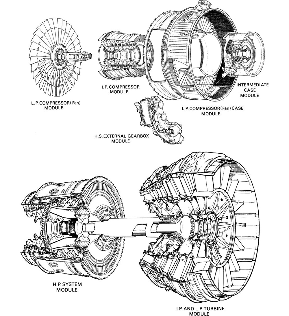
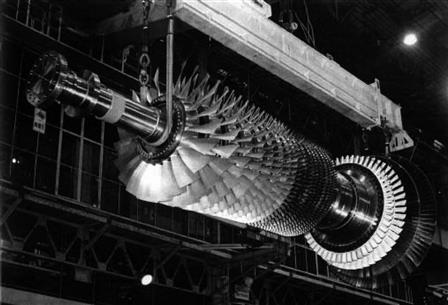
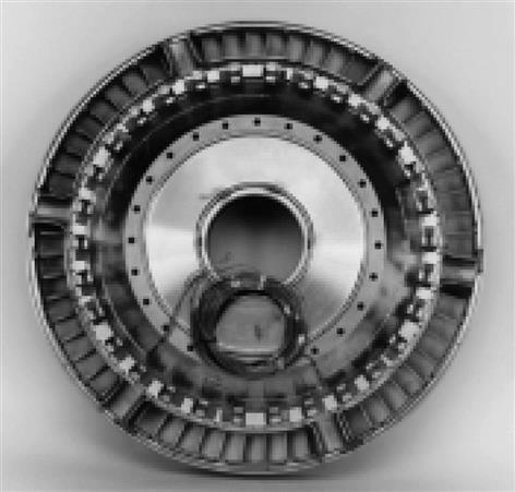
The main structure of an aero gas turbine engine is formed by a number of circular casings (see Figure 15–1) that are assembled and secured together by flanged joints and couplings located with dowels and tenons. These engines use curvic and hurth couplings to enable accurate concentricity and mating assemblies that, in turn, assist an airline operator when maintenance is required.
Manufacturing Strategy
Manufacturing is changing and will continue to change to meet the increasing demands of aeroengine components for fuel efficiency, cost and weight reductions, and being able to process the materials required to meet these demands.
With the advent of microprocessors and extending the use of the computer, full automation of components considered for in-house manufacture are implemented in line with supply groups manufacturing strategy, all other components being resourced within the worldwide supplier network.
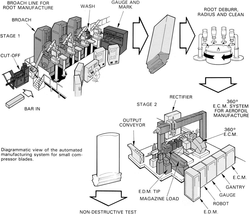
This automation is already applied in the manufacture of cast turbine blades with the seven cell and computer numerical controlled (C.N.C.) grinding centers, laser hard facing, and film cooling hole drilling by electro-discharge machining (E.D.M.). Families of turbine and compressor discs are produced in flexible manufacturing cells, employing automated guided vehicles delivering palletized components from computerized storage to C.N.C. machining cells that all use batch of one technique. The smaller blades, with very thin airfoil sections, are produced by integrated broaching and 360° electro-chemical machining (E.C.M.) while inspection and processing are being automated using the computer.
Tolerances between design and manufacturing are much closer when the design specification is matched by the manufacturing proven capability.
Computer aided design (C.A.D.) and computer aided manufacture (C.A.M.) provides an equivalent link when engine components designed by C.A.D. can be used for the preparation of manufacturing drawings, programs for numerically controlled machines, tool layouts, tool designs, operation sequence, estimating, and scheduling. Computer simulation allows potential cell and flow line manufacture to be proven before physical machine purchase and operation, thus preventing equipment not fulfilling their intended purpose.
Each casing is manufactured from the lightest material commensurate with the stress and temperatures to which it is subjected in service. For example, magnesium alloy composites and materials of sandwich construction are used for air intake casings, fan casings, and low-pressure compressor casings, since these are the coolest parts of the engine. Alloy steels are used for the turbine and nozzle casings where the temperatures are high and because these casings usually incorporate the engine rear mounting features. For casings subjected to intermediate temperatures, i.e., by-pass duct and combustion outer casings, aluminum alloys and titanium alloys are used.
Forging
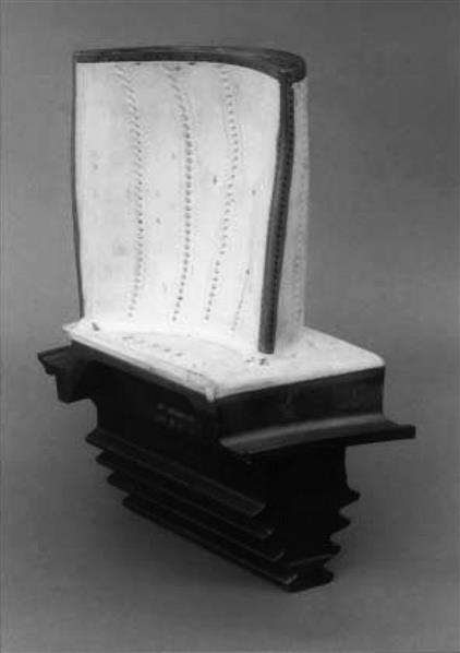
The engine drive shafts, compressor discs, turbine discs, and gear trains are forged to as near optimum shape as is practicable commensurate with non-destructive testing, i.e., ultrasonic, magnetic particle, and penetrant inspection. With turbine and compressor blades, the accurately produced thin airfoil sections with varying degrees of camber and twist, in a variety of alloys, entails a high standard of precision forging (see Figure 15–2). Nevertheless precision forging of these blades is a recognized practice and enables one to be produced from a shaped die with the minimum of further work.

The high operating temperatures at which the turbine discs must operate necessitate the use of nickel-based alloys. The compressor discs at the rear end of the compressor are produced from creep-resisting steels, or even nickel-based alloys, because of the high temperatures to which they are subjected. The compressor discs at the front end of the compressor are produced from titanium. The higher strength of titanium at the moderate operating temperatures at the front end of the compressor, together with its lower weight, provides a considerable advantage over steel.
Forging calls for a very close control of the temperature during the various operations. An exceptionally high standard of furnace control equipment, careful maintenance and cleanliness of the forging hammers, presses, and dies are essential.
Annular combustion rings can be cold forged to exacting tolerances and surfaces, which alleviates the need for further machining before welding together to produce the combustion casing.
H.P. compressor casings of the gas turbine engine are forged as rings or half rings which, when assembled together, form the rigid structure of the engine. They are produced in various materials, i.e., stainless steel, titanium, and nickel alloys.
Casting
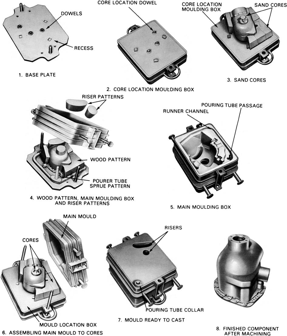
An increasing percentage of the gas turbine engine is produced from cast components using sand casting (Figure 15–3), die casting, and investment casting techniques; the latter becoming the foremost in use because of its capability to produce components with surfaces that require no further machining. It is essential that all castings are defect free by the disciplines of cleanliness during the casting process otherwise they could cause component failure.
All casting techniques depend upon care with methods of inspection such as correct chemical composition, testing of mechanical properties, radiological and microscopic examination, tensile strength, and creep tests.
The complexity of configurations together with accurate tolerances in size and surface finish is totally dependent upon close liaison with design, manufacturing, metallurgist, chemist, die maker, furnace operator, and final casting.
In the pursuit of ever increasing performance, turbine blades are produced from high temperature nickel alloys that are cast by the investment casting or “lost wax” technique. Directionally solidified and single crystal turbine blades are cast using this technique in order to extend their cyclic lives.
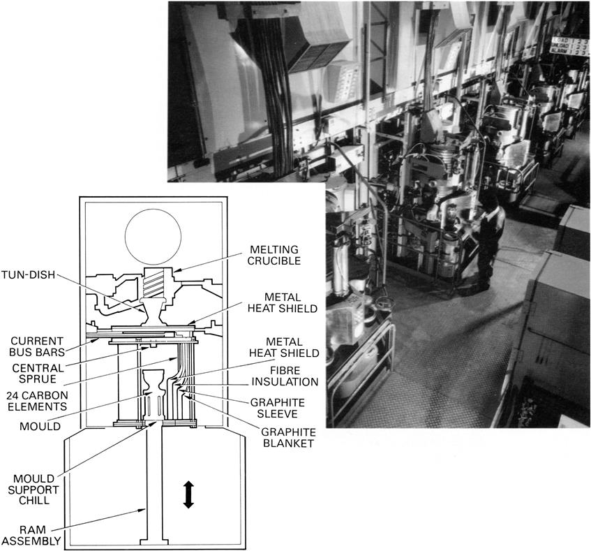
Figure 15–4 illustrates automatic casting used in the production of equi-axed, directional solidified, and single crystal turbine blades. The lost wax process is unparalleled in its ability to provide the highest standards of surface finish, repeatable accuracy, and surface detail in a cast component. The increasing demands of the engine have manifested in the need to limit grain boundaries and provide complex internal passages. The molds used for directional solidified and single crystal castings differ from conventional molds in that they are open at both ends, the base of a mold forms a socketed bayonet fitting into which a chill plate is located during casting. Metal is introduced from the central sprue into the mold cavities via a ceramic filter. These and orientated seed crystals, if required, are assembled with the patterns prior to investment. Extensive automation is possible to ensure the wax patterns are coated with the shell material consistently by using robots. The final casting can also have their rises removed using elastic cut-off wheels driven from robot arms (see Figure 15–5).
Fabrication
Major components of the gas turbine engine, i.e., bearing housings, combustion and turbine casings, exhaust units, jet pipes, by-pass mixer units, and low-pressure compressor casings, can be produced as fabricated assemblies using sheet materials such as stainless steel, titanium, and varying types of nickel alloys.
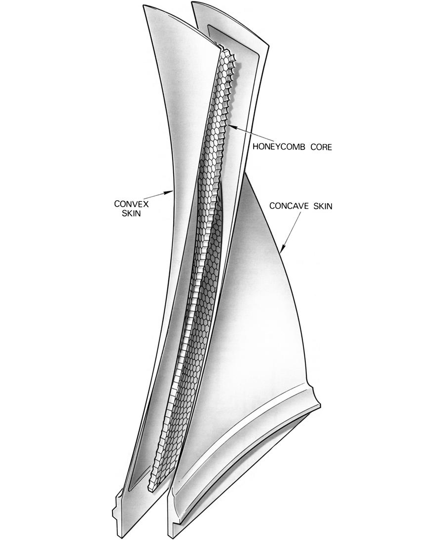
Other fabrication techniques for the manufacture of the low pressure compressor wide chord fan blade comprise rolled titanium side panels assembled in dies, hot twisted in a furnace, and finally hot creep formed to achieve the necessary configuration. Chemical milling is used to recess the center of each panel which sandwiches a honeycomb core; both panels and the honeycomb are finally joined together using automated furnaces where an activated diffusion bonding process takes place (see Figure 15–6).
Welding
Welding processes are used extensively in the fabrication of gas turbine engine components, i.e., resistance welding by spot and seam, tungsten inert gas, and electron beam are amongst the most widely used today. Care has to be taken to limit the distortion and shrinkage associated with these techniques.
Tungsten Inert Gas (T.I.G.) Welding
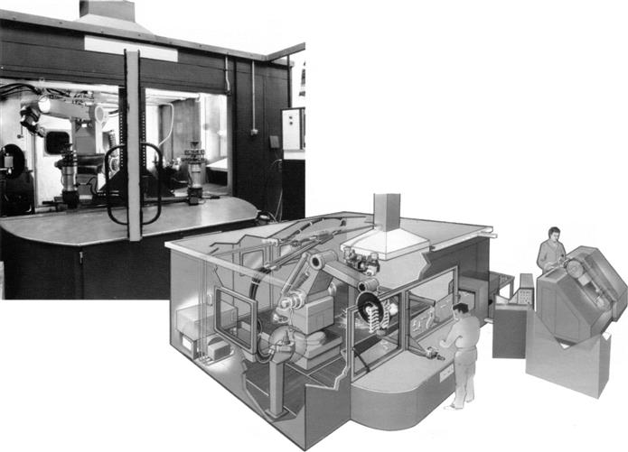
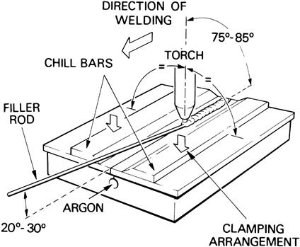
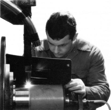
The most common form of tungsten inert gas welding, Figure 15–7, in use is the direct current straight polarity, i.e., electrode negative pole. This is widely used and the most economical method of producing high quality welds for the range of high strength/high temperature materials used in gas turbine engines. For this class of work, high purity argon shielding gas is fed to both sides of the weld and the welding torch nozzle is fitted with a gas lens to ensure maximum efficiency for shielding gas coverage. A consumable 4% thoriated tungsten electrode, together with a suitable non-contact method of arc starting, is used and the weld current is reduced in a controlled manner at the end of each weld to prevent the formation of finishing cracks. All welds are visually and penetrant inspected and, in addition, welds associated with rotating parts, i.e., compressor and/or turbine, are radiologically examined to quality acceptance standards. During welding operations and to aid in the control of distortion and shrinkage the use of an expanding fixture is recommended and, whenever possible, mechanized welding employed together with the pulsed arc technique is preferred. A typical T.I.G. welding operation is illustrated in Figure 15–8.
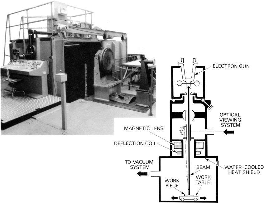
Electron Beam Welding (E.B.W.)
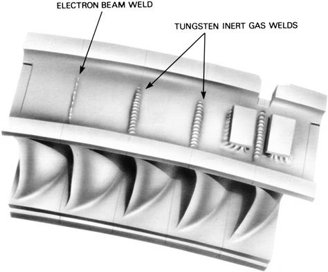
This system, which can use either low or high voltage, uses a high power density beam of electrons to join a wide range of different materials and of varying thickness. The welding machine (Figure 15–9) comprises an electron gun, optical viewing system, work chamber and handling equipment, vacuum pumping system, high or low voltage power supply, and operating controls. Many major rotating assemblies for gas turbine engines are manufactured as single items in steel, titanium, and nickel alloys and joined together, i.e., intermediate and high-pressure compressor drums. This technique allows design flexibility in that distortion and shrinkage are reduced and dissimilar materials, to serve quite different functions, can be homogeneously joined together. For example, the H.P. turbine stub shafts requiring a stable bearing steel welded to a material that can expand with the mating turbine disc. Automation has been enhanced by the application of computer numerical control (C.N.C.) to the work handling and manipulation. Seam tracking to ensure that the joint is accurately followed and close loop under bead control to guarantee the full depth of material thickness is welded. Focus of the beam is controlled by digital voltmeters. See Figure 15–10 for weld examples.
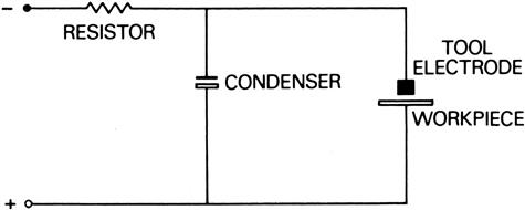
Electro-Chemical Machining (E.C.M.)
This type of machining employs both electrical and chemical effects in the removal of metal. Chemical forming, electrochemical drilling, and electrolytic grinding are techniques of electro-chemical machining employed in the production of gas turbine engine components.
The principle of the process is that when a current flows between the electrodes immersed in a solution of salts, chemical reactions occur in which metallic ions are transported from one electrode to another (Figure 15–11). Faraday’s law of electrolysis explains that the amount of chemical reaction produced by a current is proportional to the quantity of electricity passed.
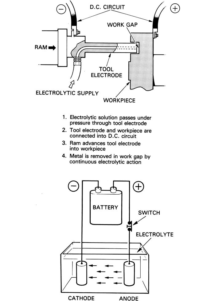
In chemical forming (Figure 15–11), the tool electrode (the cathode) and the workpiece (the anode) are connected into a direct current circuit. Electrolytic solution passes, under pressure, through the tool electrode and metal is removed from the work gap by electrolytic action. A hydraulic ram advances the tool electrodes into the workpiece to form the desired passage.
Electrolytic grinding employs a conductive wheel impregnated with abrasive particles. The wheel is rotated close to the surface of the workpiece in such a way that the actual metal removal is achieved by electro-chemical means. The by-products, which would inhibit the process, are removed by the sharp particles embodied in the wheel.
Stem drilling and capillary drilling techniques are used principally in the drilling of small holes, usually cooling holes, such as required when producing turbine blades.
Stem Drilling
This process consists of tubes (cathode) produced from titanium and suitably insulated to ensure a reaction at the tip. A 20% solution of nitric acid is fed under pressure onto the blade producing holes generally in the region of 0.026 in. diameter. The process is faster in operation than electro-discharge machining and is capable of drilling holes up to a depth 200 times the diameter of the tube in use.
Capillary Drilling
This process is similar to stem drilling but uses tubes produced from glass incorporating a core of platinum wire (cathode). A 20% nitric acid solution is passed through the tube onto the workpiece and is capable of producing holes as small as 0.009 in. diameter. Depth of the hole is up to 40 times greater than the tube in use and therefore determined by tube diameter.
Automation has also been added to the process of electro-chemical machining (E.C.M.) with the introduction of 360° E.C. machining of small compressor blades, see Figure 15–12. For some blades of shorter length airfoil, this technique is more cost effective than the finished shaped airfoil when using precision forging techniques. Blades produced by E.C.M. employ integrated vertical broaching machines which take pre-cut lengths of bar material, produce the blade root feature, such as a fir-tree, and then by using this as the location, fully E.C.M. from both sides to produce the thin airfoil section in one operation.
Electro-Discharge Machining (E.D.M.)
This type of machining removes metal from the workpiece by converting the kinetic energy of electric sparks into heat as the sparks strike the workpiece.
An electric spark results when an electric potential between two conducting surfaces reaches the point at which the accumulation of electrons has acquired sufficient energy to bridge the gap between the two surfaces and complete the circuit. At this point, electrons break through the dielectric medium between the conducting surfaces and, moving from negative (the tool electrode) to positive (the workpiece), strike the latter surface with great energy; Figure 15–13 illustrates a typical spark erosion circuit.
When the sparks strike the workpiece, the heat is so intense that the metal to be removed is instantaneously vaporized with explosive results. Away from the actual center of the explosion, the metal is torn into fragments, which may themselves be melted by the intense heat. The dielectric medium, usually paraffin oil, pumped into the gap between the tool electrode and the workpiece, has the tendency to quench the explosion and to sweep away metallic vapor and molten particles.
The amount of work that can be effected in the system is a function of the energy of the individual sparks and the frequency at which they occur.
The shape of the tool electrode is a mirror image of the passage to be machined in the workpiece and, to maintain a constant work gap, the electrode is fed into the workpiece as erosion is effected.
Composite Materials and Sandwich Casings
High power to weight ratio and low component costs are very important considerations in the design of any aircraft gas turbine engine, but when the function of such an engine is to support a vertical take-off aircraft during transition, or as an auxiliary power unit, then the power to weight ratio becomes extremely critical.
In such engines, the advantage of composite materials allows the designer to produce structures in which directional strengths can be varied by directional lay-up of fibers according to the applied loads.
Composite materials have and will continue to replace casings, which, in previous engines, would have been produced in steels or titanium. By-pass duct assemblies comprising three casings are currently being produced up to 4ft 7in. in diameter and 2ft 0in. in length using pre-cured composite materials for the casing fabric. Flanges and mounting bosses are added during the manufacturing process, which are then drilled for both location and machined for peripheral feature attachment on C.N.C. machining centers, which at one component load, completely machine all required features. Examples of composite material applications are illustrated in Figure 15–14.
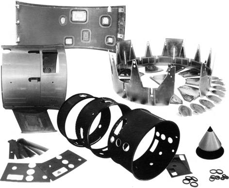
Conventional cast and fabricated casings and cowlings are also being replaced by casings of sandwich construction that provide strength allied with lightness and also act as a noise suppression medium. Sandwich construction casings comprise a honeycomb structure of aluminum or stainless steel interposed between layers of dissimilar material. The materials employed depend upon the environment in which they are used.
Inspection
During the process of manufacture, component parts need to be inspected to ensure defect-free engines are produced. Using automated machinery and automated inspection, dimensional accuracy is maintained by using multi-directional applied probes that record sizes and position of features. The C.N.C. inspection machine can inspect families of components at pre-determined allotted intervals without further operator intervention. In the chip machining (i.e., turning, boring, milling etc.) and metal forming processes C.N.C. machine tools enable consistency of manufacture that can be statistically inspected, i.e., one in ten. Component integrity is achieved by use of ultrasonic, radiological, magnetic particle and penetrant inspection techniques, as well as electrolytic and acid etching to ensure all material properties are maintained to both laboratory and quality acceptance standards.
Smart Materials
Today, development work on smart materials continues. These are materials that can change their shape in response to their environment. Clearly, when further advances are made, this could revolutionize the face of manufacture.
Smart materials are designed materials that have one or more properties that can be significantly changed in a controlled fashion by external changes such as pressure or temperature. The application potential in the gas turbine industry is obvious but in the earlier stages of research. An abstract from published work relating to just one example from the research in this field, follows below. This is a rapidly growing field and holds great potential for several industries. Other keywords related to smart material are such as shape memory material (SMM) and shape memory technology (SMT).
This Small Business Innovation Research Phase I3 project focuses on developing a novel thermographic phosphor thermometry technique, combined with a thermal barrier coating (TBC) material, for monitoring gas turbine surface temperature and TBC condition (i.e., to monitor the coating for spallation and deterioration). Design of efficient and low-emission power generation gas turbines requires detailed knowledge of the temperatures, heat fluxes and flow regimes experienced by hot-gas path (HGP) components under realistic operating conditions. Hence, there is an urgent need for innovative and non-intrusive experimental techniques suitable for accurate measurement of surface temperatures in excess of 2500 K for HGP components in high-temperature regions of the gas turbine, where conventional techniques cannot be applied. In this project, a unique upconversion phosphor thermometry technology will be developed which will overcome the issues confronting widely-used down-conversion thermometry techniques. The proposed temperature sensing mechanism is independent of variations in the excitation power and environmental conditions, and hence is especially suitable for hazardous gas turbine applications. The broader impact/commercial potential of this project will be significant, because gas turbines are used to power aircraft, trains, ships, generators, and ground vehicles. Almost all manufacturers in the aerospace, transportation, and energy generation fields would benefit from the technology developed in this project. If successful, this Phase I project will directly result in an enabling technique for non-intrusive monitoring of temperature and surface conditions of materials experiencing extremely high-temperature environments. The data gathered by such a technique will also add to the scientific understanding of high-temperature combustion and fluid flow processes.
Reverse Engineering
This is a process that is normally conducted by an independent shop, not the OEMs. That said, some of these independent shops are owned and operated by people who have retired from the OEM’s ranks, so they may know the engine in question very well.
Particularly in the case of legacy engines, spare parts can be hard to find. However, end-users tend to keep their gas turbines, even if there are new models available that have far better efficiency and operating parameters. If the owner wants to keep his old engine(s) running and can’t find parts, he then gets components reengineered. Turbine blades are among the more common candidates for reengineering.
Dimensional data are captured with 3D (usually laser) scanning. Many commercial scanners are accurate to 0.001”. Higher precision machines measure within 0.0003”.4
Point cloud data and reverse engineering software produces a 3D shape that is then submitted for finite element analysis. The results are then transferred to a CAD package the results from which are then compared by a CMM (coordinate measuring machine) with the actual part. Verification processes are then done. The part then proceeds to fabrication stages, which vary considerably, depending on the performance and metallurgy required in the application.
Reengineering by Overhaul Facilities
Highly specialized metallurgical facilities develop varying processes that recover component lives and extend the time between overhauls for OEM components. Examples include powder metallurgy (using a kind of metal putty to fill in damage voids in aerfoils), hot isostatic pressing (HIPing) where a heat treatment process recovers the metallurgical grain structure of an aerfoil, different brazing techniques, coatings for erosion or corrosion resistance.
For the first five years or so after a new model is released, the OEM will not allow such an independent facility to work on their components. This makes sense, as the OEM wants to ensure his prototype has no major flaws. If none surface in five years, the OEM may himself go the independent facility to develop some repair processes that improve their image with customers. The independent facility can generally develop repairs cheaper than a large OEM. Besides they have a wealth of specialized knowledge from their customer base, which includes many whose GT warranty period has run out.
For this reason, end-users are advised to read this chapter in conjunction with Chapter 12, Maintenance, Repair and Overhaul. In fact, end-users selecting new GT packages ought to study an OEM’s track record of having their components of their older engines overhauled by independent facilities. Ones that offer a range of opportunities in this area mean potentially less downtime in the case of plant malfunction or machinery failure.
Optimization of Component Manufacture by OEMs
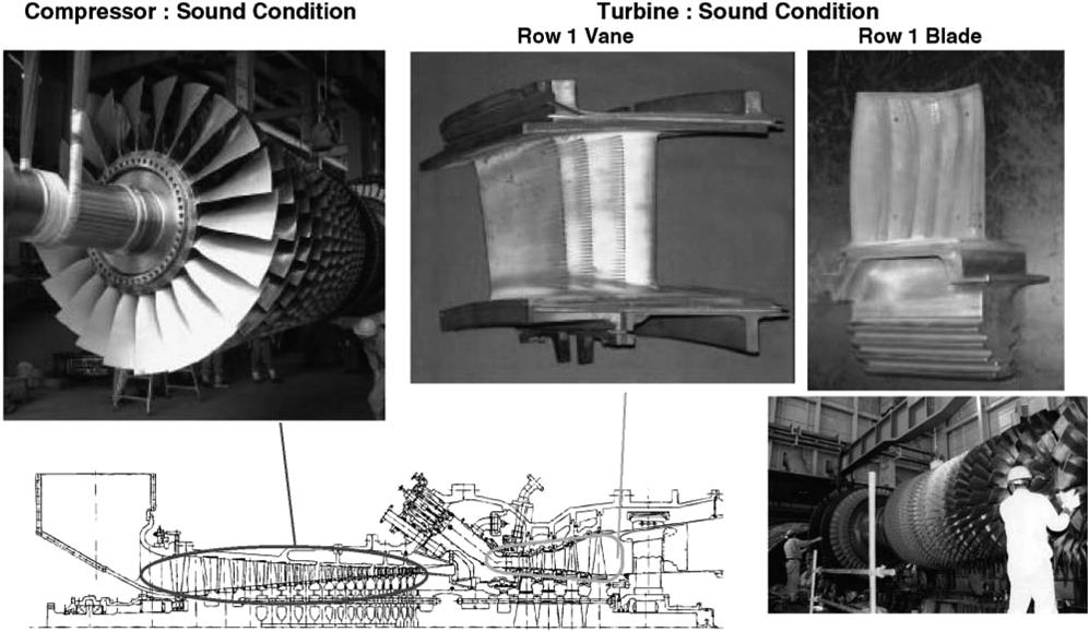
To optimize their cost effectiveness, manufacturers build on, extrapolate from and selectively reengineer the cores of their already successful engines. A case history in point follows. It describes how Mitsubishi developed its core experience with TITs of 1150 to 1350 and then to a ceiling of 1500°C (for 50 and 60 Hz gas turbines in power-generation combined-cycle applications).
Optimizing Gas Turbines with Manufacturing Technology
Case Study 1: Upgrading the Core Engine5
The next generation G class gas turbine, with turbine inlet gas temperature in the 1500°C range, has been developed by Mitsubishi Heavy Industries Ltd. (MHI). Many advanced technologies, including a high efficiency compressor, a steam cooled low NOx combustor, a high temperature and high efficiency turbine, etc., are employed to achieve high combined-cycle performance. Actually, MHI has been accumulating the operating experiences of the M501 G (60 Hz machine), a combined-cycle verification plant in MHI Takasago, Japan, achieving high performance and reliability. Also, M701G (50 Hz machine) has been accumulating the operating experience in Higashi Niigata Thermal Power Station of Tohoku Electric Power Co., Inc. in Japan.
What follows describes the technical features of M501 G/M701 G, and up-to-date operating status of the combined-cycle power plant in MHI Takasago, Japan.
MHI developed a turbine inlet temperature of 1150°C class M701D gas turbine and 1350°C class M501F/M701F gas turbines. Their high efficiency and reliability for combined-cycle applications have been proven in field operations. Based on the fact that the combined-cycle efficiency is highly dependent on the gas firing temperature, MHI has newly developed the 1500°C class M501G/M701G, both “G” series gas turbines.
Table 15–1 shows the main introductory performance specification of the M501G, in comparison with the M501F. The M501G is a heavy-duty gas turbine designed to serve the 60 Hz power generating utility. The output of the M501G is 254 MW at a turbine inlet temperature of 1°C on natural gas fuel.
TABLE 15–1
Performance of G01 g Gas Turbine [15-1]
| M501G | M501F | |
| Speed (rpm) | 3600 | 3600 |
| G/T Output (MW) | 254 | 185.4 |
| G/T Thermal efficiency (%-LHV) | 38.7 | 37.0 |
| Pressure ratio | 20 | 16 |
Development of the “G” series gas turbine was started in the early 1990s and the design was based on the following concepts, which give excellent performance and high reliability to the “G” series.
Firstly, proven features from the “F” series are kept. Secondly, the most advanced technologies in aerodynamic design, heat transfer design, and new materials for the “G” series are introduced. Thirdly, our conventional design criteria in industrial gas turbines are applied. Fourthly, the turbine inlet temperature is increased to the extent where the NOx and the metal temperature can be maintained at the same level as the “F” series. Finally, verification tests are carried out before production of the M501G gas turbine to secure their high reliability.
The trial operation of the M501G was conducted in 1997 in the combined-cycle verification plant in MHI Takasago, Japan. It was successful and the M501G commercial operation was started sequentially in June 1997. Since then, four inspections were conducted and even though some operational events were observed, the condition of each component was quite sound. Also, the availability, which defined as the actual power supply hours divided by demanded power supply hours (excluding scheduled shutdown such as periodical inspection, during the operation) was 99.2%, which indicates the high reliability of the M501G.
Design Features
The rotor of the M501G is shown in Figure 15–15.
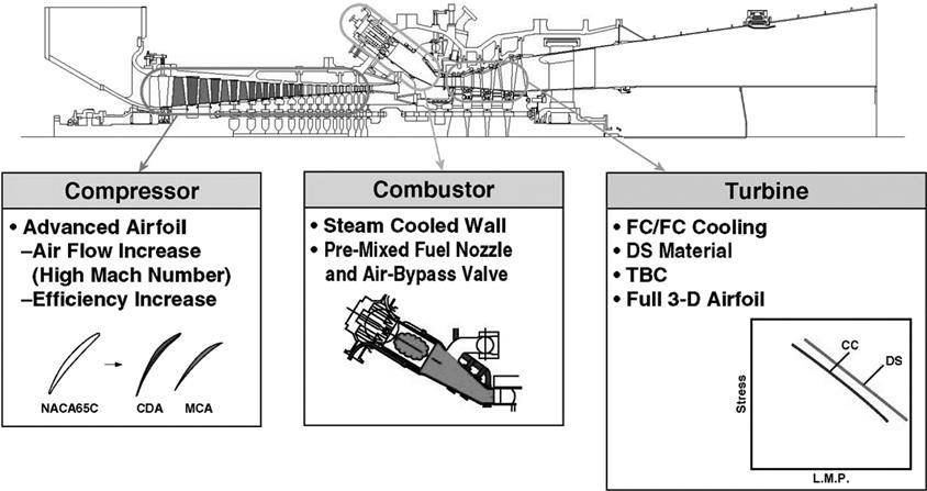
The “G” series inherits the proven NMI technology of the “F” series and employs the advanced technology shown in Figure 15–16.
Overall Structure
The basic structure of the “G” series is the same as the “F” series gas turbines. Several basic design concepts such as the two bearing single shaft structure, cold end generator drive, and axial exhaust are evident.
The single shaft rotor is made of compressor and turbine disks that are bolted with spindle bolts. The rotor is supported by two bearings, which are two-element tilting pad bearings. The thrust bearing is a double-acting type using the direct lubrication system on the compressor side.
The air inlet system delivers air to the compressor by a plenum bell mouth and covers the bearings. The compressor is an axial flow design with seventeen stages. A four-stage axial turbine is applied to maintain the optimum aerodynamic loading even at the increased firing temperature and pressure ratio.
All gas turbine casings can be horizontally split to facilitate maintenance without rotor removal. Eight radial struts support the front bearing housing and six tangential struts support the rear bearing housing. Airfoil-shaped covers protect the tangential struts from the blade path gas and support the inner and outer diffuser cones.
The individual inner turbine casings that are called blade rings are used for the stationary part of each turbine stage and can be easily removed and replaced without rotor removal. The similar structure of blade rings is applied to the compressor rear stages. Another feature of these blade rings is that they have high thermal response being independent of the outer casing and can be aligned concentric to the rotor to minimize the blade tip clearances.
Cooling circuits for the turbine section are similar to those of the “F” series. They consist of a rotor cooling circuit and four stationary vane-cooling circuits. Rotor cooling air is provided from compressor discharge air extracted from the combustor shell. This air is supplied as the cooling and seal air of the turbine disks and rotating blades after being externally cooled and filtered. Direct compressor discharge air is used to cool the first stage vane while the compressor bleed air from intermediate stages is used as the cooling air for turbine blade ring cavities and second, third, and fourth stage vanes.
Advanced Compressor
The compressor has highly efficient axial flow design. The “G” series compressor requires a larger flow rate and higher efficiency than the “F” series. The result is that this compressor has a higher Mach number. To meet this requirement, the M501G incorporates multiple circular arc (MCA) airfoils in the forward four stages of the rotating blades. Also, controlled diffusion airfoils (CDA) are applied for the rest of the stages of the rotating blades, namely from the fourth to the seventeenth stage, and all stages of the stationary vanes. The latest three-dimensional compressor blade design is employed.
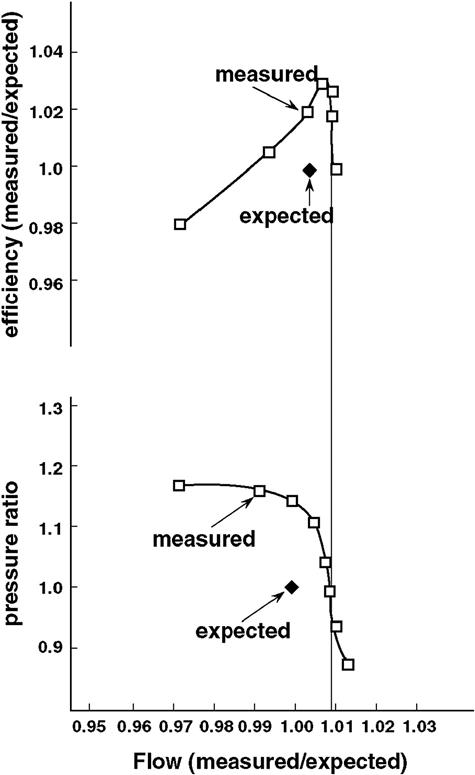
The aerodynamic performance is verified with both the cascade test and model compressor test. Model compressor test results show that primary parameters of mass flow and efficiency meet the design range as shown in Figure 15–17. Also, aerodynamic performance is proven with the MF221 gas turbine, which has a half scale compressor of the M501G.
The compressor is also equipped with variable inlet guide vanes, which improve the compressor surge characteristics during start-up and are used in the combined-cycle applications to improve part-load performance.
Dry Low NOx Steam-Cooled Combustor
The combustor design is based on the successful can-annular dry low NOx combustor developed for the “F” series. This combustor currently operates at less than 25 ppm NOx level at 1400°C turbine inlet temperature (TIT) defined as the averaged combustor outlet gas temperature.
In order to keep the same NOx level as the “F” series at 1500°C TIT, all the air discharged from the compressor should be supplied for combustion. For this reason, a premixed combustor with closed circuit steam cooling system was applied for the “G” series combustor.
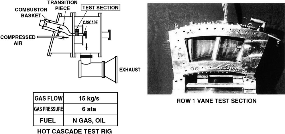
To optimize the swirl strength and the configuration of fuel ejection holes, a cold flow test was conducted. Also, atmospheric and high-pressurized combustion tests were conducted using a full-scale combustor and a fuel nozzle as shown in Figure 15–18. The test results showed 25 ppm NOx level and satisfactory wall temperatures without cooling steam leakage. The field verification test of this steam-cooled combustor has already been conducted in the M701F gas turbine to verify its durability.

High Temperature Turbine
It is essential to keep the metal temperature below the allowable limit to secure the same level of reliability at 1500°C TIT with minimum cooling airflow. To achieve a lot of advanced technologies like full coverage film cooling (FCFC), thermal barrier coating (TBC), new heat resistant material, and directionally solidification (DS) casting technology are introduced.
Several heat transfer tests like measurement of film cooling effectiveness around the airfoil and heat transfer characteristics of serpentine cooling passage with turbulence promoters under rotating conditions were conducted. Based on the results obtained from these fundamental tests, the advanced cooled turbine airfoils were designed. Figure 15–19 shows the first stage blade of the turbine.
The actual turbine blades and vanes were first verified in the hot cascade test facility shown in Figure 15–20. In the facility, the test was conducted with the maximum average inlet gas temperature up to 1550°C in order to check the margin. Gas temperature distribution at the cascade inlet is measured with total temperature probes and the metal temperature of the vane and the blade is measured with the embedded thermocouples. With the hot cascade tests, the airfoil metal temperature distribution was obtained and the cooling effectiveness was verified.
These features and technologies were finally verified through a high temperature demonstration unit (HTDU) by testing the airfoils under certain conditions. The HDTU shown in Figure 15–21 is a special core turbine with 0.6 scale turbine blades and vanes of the M501G for demonstrating the key technologies.

Materials
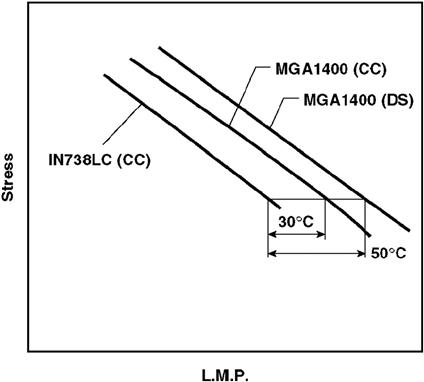
The advanced gas turbine requires heat resistant materials as well as advanced cooling technologies. For this purpose, some advanced materials for turbine blades and vanes, and thermal barrier coatings are developed. For the rotating blade material, MGA1400 alloy was developed. MGA1400 is a nickel-base super alloy and can be used for DS casting as well as for conventional casting. Compared with the IN738LC conventionally cast blade, the creep strength of the MGA1400DS blade is 50°C higher, and that of the conventionally cast MGA1400 is 30°C higher as shown in Figure 15–22. Both DS and CC blades are applied in the “G” series gas turbine.
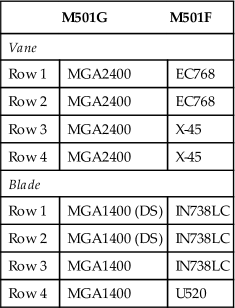
For the stationary vane material, MGA2400 alloy was developed. MGA2400 is also a nickel-base super alloy that has excellent resistance against thermal fatigue, oxidation, and hot corrosion as well as high creep strength. It also has good weldability for settlement of accessory parts and repair. Table 15–2 summarizes the materials for turbine vanes and blades.
TABLE 15–2
The M501G Turbine Blade Material [15-1]
| M501G | M501F | |
| Vane | ||
| Row 1 | MGA2400 | EC768 |
| Row 2 | MGA2400 | EC768 |
| Row 3 | MGA2400 | X-45 |
| Row 4 | MGA2400 | X-45 |
| Blade | ||
| Row 1 | MGA1400 (DS) | IN738LC |
| Row 2 | MGA1400 (DS) | IN738LC |
| Row 3 | MGA1400 | IN738LC |
| Row 4 | MGA1400 | U520 |
TBC is also important for its heat shield effect. The durability and the heat shield effect have been confirmed through many long-term field operational experiences of MF61, MF111, MF221, M7011, M501F, M701F, etc.
Long-Term Operating Experience
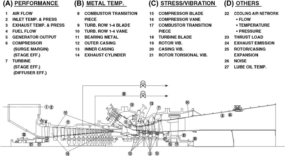
NMI constructed a long-term verification test facility with the M501G as a complete combined-power plant in its Takasago Machinery Works. NMI started the trial operation of the M501G in January 1997 to verify the performance and reliability. During the trial operation, more than 1800 instrumentation probes were installed in the gas turbine. Figure 15–23 shows the special measurement items. The flow path characteristics, metal temperatures, pressures, strains, sound pressure levels, exhaust emissions, etc., were measured over the full range of operating conditions.
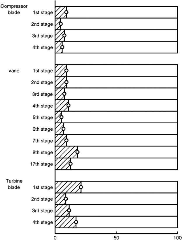
All important characteristics, including the cooling characteristics and component reliability, were verified. As an example, measured vibratory stresses of the blades and vanes are shown in Figure 15–24. They were measured for the first stage to the fourth stage blades, the first stage to the eighth stage and the seventeenth stage vanes of the compressor and the first stage to the fourth stage blades of the turbine during starting period, rated speed, and up to 110% of the rated speed. These items were measured by a non-contact method using optical fibers for compressor blades and by strain gauges for compressor vanes and turbine blades (with telemeter). The results show that the vibratory stresses are low enough compared with the allowable values.
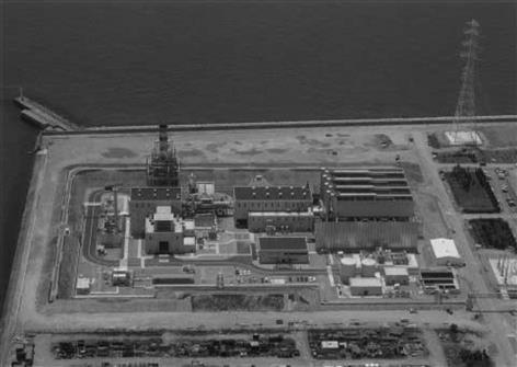
At the end of June 1997, the combined-cycle verification plant passed the Ministry of International Trade and Industry (MITI)’s qualification test as an industrial power plant, which consists of one M501G gas turbine, one HRSG and one steam turbine and started commercial operation as the long-term verification test. The plant layout is shown in Figure 15–25. The electricity is sent to the grid of a domestic utility company. As this plant operates on demand of the utility company, it has mainly been operated with Daily Start and Stop (DSS) mode. Accumulated total operating hours/start-and-stop cycles are 10,898 hours/612 cycles at the end of October 2000. It is still accumulating operating experience successfully.
The following is the detailed explanation of each operation and inspection. The result shows the high reliability of the M501G.
June–October 1997
The M501G started its first verificational operation for summer peaking duty. In October, summer peaking duty was completed and the first inspection of the M501G started. The hot gas path components like steam-cooled combustor, advanced cooled turbine vanes, and blades were found to be sound except minor cracks of steam cooled combustor transition piece exhaust mouth comers.
December 1997–March 1998
After the first inspection, the M501G was back in service in December 1997. The load demand in winter tends to be lower, but to confirm the soundness in preparation for the next summer peaking duty, the second inspection was conducted in March 1998. The inspection proved the hot gas path components to be sound.
June 1998–November 1998
The M501G was back in service. The result of the inspection in November 1998 showed no severe problems and everything was in sound condition. Until the next operation started in July 1999, the operating test of the M501H, which has steam cooled first and second stage vanes and blades as well as the steam-cooled combustor, was conducted and the results were successful.
July 1999–March 2000
The M501G was in service again for summer peaking duty. Accumulated operating hours/start-and-stop cycles were 8633 hours/514 cycles. The result of the inspection in March 2000 was very good as shown in Figure 15–26 even though partial peeling of TBC at row 1 blade was observed.
May–October 2000
After the fourth inspection, the M501G has returned to service and is successfully accumulating operating experience. The result of the inspection in October 2000 was fine by this inspection, and accumulated operating hours/start-and-stop cycles are 10,898 hours/612 cycles. The availability defined as the actual power supply hours over the demanded power supply hours reaches 99.2%. Also, the M701G, the “G” series gas turbine of 50 Hz, started a trial operation in October 1998. The plant started the commercial operation for the domestic utility company in July 1999 and has been successfully accumulating the operating hours and start-and-stop cycles of 9842 hours/63 times for the No. 1 gas turbine and 9350 hours/52 times for the No. 2 gas turbine. Since the gas turbine has never stopped except for the scheduled outage, availability defined as the actual power supply hours over the demanded power supply hours is 100%.
Because the high reliability of the M501G/M701G is verified through these operations, MHI has already received the order of 17 M501Gs and 7 M701Gs by the end of October 2000 and further potential orders are expected especially for the M501G. This would be a great help for energy savings and environmental conservation.
In summary, the M501G full load test with special measurement, which was conducted during the trial operation in February 1997, showed its high efficiency and high reliability and low environmental impact. At the end of June 1997, the combined-cycle plant with the M501G was put into long-term verificational operation after receiving MITI’s certification.
By the end of October 2000, the plant has been successfully accumulating the 10,898 operating hours to keep up with the electricity demand from the utility company and start-and-stop cycles reached 612 cycles. The availability of 98.6% is kept. The M501G experienced five inspections and the condition of each component was quite good. These inspection results showed the high reliability of the M501G. The M501G would make a great contribution to energy savings and good global environmental issues.
Raising Serviceability Ceilings
With TIT upper limits being pushed upward, designers of different components within the gas turbine are all forced to seek new materials or manufacture methods or both. The different OEMs employ different technologies and strategies, several of which are discussed in cases in several of this book’s chapters.
One summarized example here is a study made of the spray forming of a high(er)-temperature casing (participants were DERA, UK, and Rolls Royce, UK). One of the key parameters of concern with any such work is creep behavior.
A summary of this work’s conclusions, to the point reported in a paper, is as follows.6
Many current gas turbine casings are manufactured using conventional wrought processing routes. Although well established this approach often requires numerous and complex processing steps. This can result in relatively long component lead times and high part costs. In an attempt to reduce lead times and cost, the production of parts using the spray-forming process is under consideration.
In modern gas turbine designs structural casings provide a gas tight pressure vessel, structural support for internal and external fixtures, and in the event of a catastrophic failure component containment. These casings are generally nickel, steel, or titanium depending upon the usage temperature and specific application. However, in all cases the casings are manufactured using a wrought processing route.
Generally casing structures are fabricated from ring rolled flanges and wrought sheet that are welded together to produce the final component geometry. A typical process route for the production of such a casing would be to take a cast ingot, forge to size, pierce, and then ring roll the pierced component to produce a flange of the required diameter and thickness. The wrought sheet would then be formed to shape and welded to the ring-rolled flanges. This process involves many manufacturing steps, is costly, time consuming, and requires the selected alloy to exhibit good forming and welding characteristics.
For alloys that are produced in large quantities the production of casings via the wrought route can be carried out reasonably cost effectively. However, due to the requirement for increased combustion temperatures and higher pressures many of the current materials utilized as combustion and turbine casings are rapidly reaching the extremes of their temperature capability. In the case of the combustion casing support structure, the front of the combustion casing sees wall temperatures approaching 650°C. In this case alloys, such as the nickel-base alloy W718, which is widely used as a combustor support casing, are becoming severely creep limited. Therefore, new higher temperature nickel-base alloys, such as RS5, W939, CM247LC, and MarM002, are under consideration to replace W718, since they offer improved creep capability.
Much development effort has been expended in developing and assessing these new alloys for engine applications and a significant proportion of the required work has now been completed. However, as a general rule an alloy that exhibits improved creep resistance (i.e., improved resistance to deformation at elevated temperature) is also more difficult to produce via conventional wrought processing routes, such as forging and rolling. Furthermore, ease of weldability can be an issue with these higher performance alloys, as can the availability and cost of wrought product. Consequently, the introduction of these elevated temperature materials may demand the application of alternative processing techniques. One alternative technique under consideration is spray forming.
Spray Forming
The spray forming of components requires the atomization and spraying of molten metal onto a suitably shaped mandrel. Generally the material is melted by induction heating, and then atomized using an inert gas (usually Ar). The atomized metal is sprayed into a deposition chamber held under a reduced pressure and deposited onto a rotating mandrel. Computer control of the spray deposition process means that profiled “near net shaped” casings can be produced. Following deposition the porous pre-form is consolidated by hot isostatic pressing, ring rolled (if necessary) to the final size, and then machined to the final component geometry. The large reduction in process steps that this approach enables makes significant cost reductions feasible for many alloys. However, for some of the higher performance alloys that are difficult to wrought process, spray forming may prove to be the only viable production route. In addition to cost spray forming also has the advantage that a fine grain sized and chemically homogeneous product is produced, which again offers benefits over conventional process routes.
Casing Fabrication
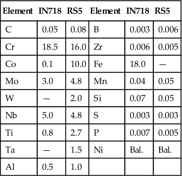
In this section the fabrication of a combustion chamber support casing via spray forming is considered. The material selected for study is the high performance nickel-base alloy RS5, which has been identified as a potential replacement alloy for 1N718 for a number of casing applications. The composition of RS5 compared to 1N718 is shown in Table 15–3. The microstructure and mechanical properties of a hot isostatic pressed (HIP) and heat-treated pre-form was evaluated.
TABLE 15–3
Typical Chemical Compositions (wt%) of Alloys IN718 and RS5 [15-2]
| Element | IN718 | RS5 | Element | IN718 | RS5 |
| C | 0.05 | 0.08 | B | 0.003 | 0.006 |
| Cr | 18.5 | 16.0 | Zr | 0.006 | 0.005 |
| Co | 0.1 | 10.0 | Fe | 18.0 | — |
| Mo | 3.0 | 4.8 | Mn | 0.04 | 0.05 |
| W | — | 2.0 | Si | 0.07 | 0.05 |
| Nb | 5.0 | 4.8 | S | 0.003 | 0.003 |
| Ti | 0.8 | 2.7 | P | 0.007 | 0.005 |
| Ta | — | 1.5 | Ni | Bal. | Bal. |
| Al | 0.5 | 1.0 |
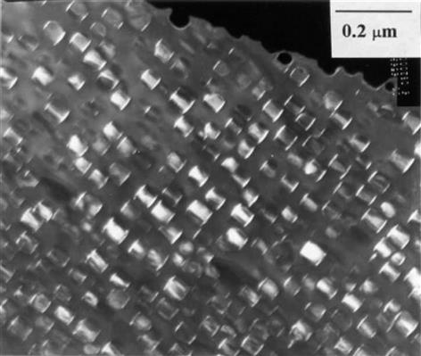
Microstructure of Processed and Heat Treated RS5
The microstructure of the spray-formed RS5 after HIPping, ring-rolling and heat treatment is shown in Figure 15–27. As can be seen from this figure the microstructure is primarily equi-axed, with a grain size ranging from 50–350 microns. The mean grain size was determined as being 100 microns. Electron back-scattered diffraction patterns showed that the microstructure did not contain any evidence of texture, as would be expected from a spray-formed deposit.
Mechanical Properties of RS5
A full mechanical property evaluation of the spray-formed RS5 was carried out to assess the suitability of the material for casing applications.
Tensile: The tensile strength of spray-cast, HIPped and ring rolled RS5 is comparable to, or better than, typical values for wrought 1N718 over the temperature range evaluated; with the strength of RS5 being retained to at least 60°C higher than 1N718. The elongation of RS5 is comparable to 1N718 in the range 20–600°C but at temperatures greater than 750°C it is significantly lower.
Creep: Comparison of the creep behavior of RS5 and 1N718 again indicates that RS5 exhibits a temperature advantage of around 60°C over 1N718 at elevated temperatures.
Fatigue: In terms of the fatigue properties, RS5 was found to be approximately comparable to typical values for wrought.
In summary, the deposition and consolidation of spray-formed RS5 results in a chemically homogeneous and equiaxed product, with little evidence of porosity or voiding. Mechanical testing of the spray-formed and processed material has clearly demonstrated that the material is broadly comparable to IN718, but exhibits a significant improvement in its properties at elevated temperature. An analysis of the data indicates that RS5 has a temperature advantage of around 60°C over IN718, in terms of tensile strength and creep resistance.
However, tensile, creep, and fatigue testing have all shown that the material is highly susceptible to intergranular failure at elevated temperatures. It is clear though that considerable scope exists to modify either the composition or processing routes in an attempt to improve the behavior of the material at elevated temperatures.
It is clear that RS5 does offer an increased temperature capability compared to IN718. However, at present the cost of processing RS5 via the spray-forming route is prohibitive. The major advantage offered by the spray-forming route is the ability to process high strength alloys that are not susceptible to wrought processing. As higher combustion temperatures are realized the need for spray-formed product is likely to increase considerably.
Creep Resistance Advancements
Creep Resistance of Materials for Microturbine Recuperators
Microturbines evolved from automotive and small aerospace turbine applications. They have caught the US Department of Energy’s (DOE’s) attention enough that they are among DOE’s closely pursued optimization projects. They have also caught public attention to the point that it will not be long before the “PT” (personal turbine) is talked about as the “PC” (personal computer) now is. (Also see Chapter 16 on microturbines and hybrids.)
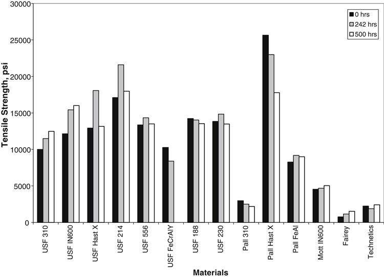
Microturbines run faster than conventional gas turbines and the heat balance of a microturbine system is such that a recuperator is essential for optimum efficiencies. With the recuperator, as with many other components on gas turbine engines, the limiting design parameter is creep, as a development study outlines. That study,7 funded by Oak Ridge National Laboratories, concludes: “A group of heat-resistant and oxidation/corrosion resistant austenitic stainless alloys have been processed into 1.3 mm foils and creep-rupture tested at 750°C and 100 MPa.” See Table 15–4.
TABLE 15–4
Compositions of Heat-Resistant Austenitic Stainless Alloys Processed into Foils (wt%) [15-3]
| Alloy/Vendor | Fe | Cr | Ni | Mo | Nb | C | Si | Ti | Al | Others |
| 347 steel (Allegheny-Ludlum) | 68.7 | 18.3 | 11.2 | 0.3 | 0.64 | 0.03 | 0.6 | 0.001 | 0.003 | 0.2 Co |
| Modified 803 (Special Metals, developmental) | 40 | 25 | 35 | n.a. | n.a. | 0.05 | n.a. | n.a. | n.a. | n.a. |
| Thermie-alloy (Special Metals) | 2.0 | 24 | 48 | 0.5 | 2.0 | 0.1 | 0.5 | 2.0 | 0.8 | 20 Co |
| Alloy 120 (Haynes International) | 33 | 25 | 32.3 | 2.5 max | 0.7 | 0.05 | 0.6 | 0.1 | 0.1 | 3 Co max, 3 W max, 0.2 N |
| Alloy 230 (Haynes International) | 3 max | 22 | 52.7 | 2 | — | 0.1 | 0.4 | — | 0.3 | 5 Co max, 14 W, + trace La |
| Alloy 214 (Haynes International) | 3.0 | 16 | 76.5 | — | — | — | — | — | 4.5 | + minor Y |
| Alloy 625 (Special Metals) | 3.2 | 22.2 | 61.2 | 9.1 | 3.6 | 0.02 | 0.2 | 0.23 | 0.16 |

Ceramic Components
Considered a distant, esoteric prospect only a scant few decades ago, the ceramic turbine is fast approaching reality. Gas turbines that use ceramic coatings and selected components that are ceramic or partially ceramic are already part of mainstream technology. Improvement of this technology continues, sponsored in the United States, in part by the US DOE. The following cases provide details of design, testing, and operational strategies that involve ceramics components and point the way for work in this discipline to continue.
Case Study 2: Ceramic Vanes for a Model 501-K Industrial Turbine Demonstration8
The approach for this project is to design and demonstrate ceramic first-stage vanes in a Rolls Royce Allison Model 501-K turbine. These vanes operate at similar (and somewhat higher) temperatures as the second-stage vanes of advanced turbines. Consequently, a successful demonstration of first-stage vanes in the current generation Model 501-K turbine could provide a stepping stone to using ceramic vanes in second-stage and downstream rows of future generation advanced turbines.
Project Summary
Activities of the DOE/Rolls Royce Allison ceramic vane project include the following:
• Design, analyses, and fabrication of ceramic first-stage vanes and their metal mounts for retrofit into Model 501-K turbines
• Thermal shock proof tests of the ceramic vanes
• Engine validation test of the ceramic vanes and their metal mounts
• Phase 1 demonstration of the first-stage ceramic vanes/mounts in a Model 501-K turbine at a commercial site to assess design integration and materials compatibility
• Phase 2 demonstration with an optimized vane/mount redesign
These activities have been completed through the Phase 1 demonstration. Operation of an Exxon turbine for a total of 815 hr (793 hr at an Exxon plant and 22 hr proof test) was achieved. The Phase 2 demonstration was originally planned to accommodate any redesign needs of the metal mounts for the ceramic vanes, because past experience has shown the challenges of integrating structural ceramic components with metallic support structures. However, the metallic mounts performed successfully in the 501-KB5 Phase 1 demonstration of first-stage ceramic vanes. Since the Phase 1 demonstration identified a significant issue of ceramic oxidation, the Phase 2 demonstration will address the resolution of the oxidation issue.
Ceramic Vane/Mount Design and Analyses
Vanes
The AlliedSignal AS 800 silicon nitride ceramic was used for the first-stage ceramic vanes. The ceramic vanes were designed to facilitate manufacturability and relatively low cost. The vane design involves a single airfoil and simple platforms. The mounting arrangement (described in the next section) enables minimal final machining of the vane to reduce costs. The ceramic vane has been designed with a thinner airfoil than for the Model 501 turbine first metal vane. Analyses showed that the thinner vane was necessary for acceptable thermal shock stresses during emergency shutdown of the turbine (the highest stress condition).
Thermal and stress analyses indicated a maximum emergency shutdown stress of 207 MPa (30.0 ksi) in the vane mid span trailing edge region. A maximum steady-state stress of 192 MPa (27.9 ksi) was calculated at maximum continuous power for the turbine. The location of the maximum steady-state stress was also in the mid span trailing edge region. The calculated fast fracture probability of survival for the 60-vane engine set exceeds 99.99% for all of the emergency shutdown and maximum continuous power conditions that were analyzed.
Stress rupture tests of the AS 800 silicon nitride material used for the ceramic vane with durations up to 10,000 hr have been conducted at Oak Ridge National Laboratory (ORNL) and the University of Dayton at significantly higher temperatures and somewhat lower stresses than calculated for the vane at maximum continuous power conditions. No failures were experienced in 4500 hr by any of the specimens from a properly processed batch of the AS 800 ceramic. Retained strengths of specimens measured after surviving the 4500 hr stress rupture test exceeded 490 MPa (71 ksi), which is substantially higher than the highest calculated emergency shutdown stress of 207 MPa (30.0 ksi) for the Model 501-K ceramic vanes. The results of these tests provided a basis for conducting a long-term field test of the AS 800 ceramic vanes.
Mounts
Figure 15–28 illustrates the mounting arrangement for the ceramic vanes. To minimize mount loads and stresses, the vanes are not gripped or otherwise hard mounted but instead are seated in circumferential grooves of the inner and outer mount segments. Ceramic cloth is used at the interfaces between the metal mount segments and the outer surfaces of the vane platforms. This compliant material reduces ceramic contact loads and stresses from the mounts and also insulates the ceramic/metal interface. Insulation allows the mounts to operate at lower temperatures in their alloy working range and reduces the thermal gradient in the ceramic vane, which is the primary source of steady-state stress.
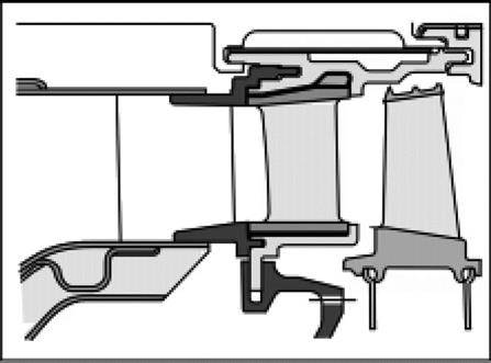
Ceramic Vane/Mount Assembly
Figure 15–29 shows the first-stage ceramic vane/mount assembly that replaces a similar metal vane assembly used for conventional Model 501-K turbines. The inner vane support and an outer sheet metal band that holds the assembly together are common to both the ceramic and metal vane assemblies. All of the other parts of Figure 15–29 were designed for retrofit of the first-stage ceramic vanes into Model 501-K turbines. The Figure 15–29 front view also shows the saddles that position the transition sections from the six can combustors of the Model 501-K turbines. Consequently, 10 of the 60 first-stage ceramic vanes are located at the exit of each of the transition sections from the six combustor cans.
Ceramic Vane Thermal Shock Tests
Trailing edge thickness and other measurements were taken on each of the 87 AS 800 ceramic vanes received from AlliedSignal. The vanes were analyzed using fluorescent penetrant and x-ray analyses. The vanes were then exposed in an atmospheric combustor rig to thermal shock tests. Visual, fluorescent, and x-ray analyses conducted after the thermal shock tests revealed that only one vane had evidence of a possible crack and was questionable for operation in the turbine.
Ceramic Vane/Mount Proof Tests
Turbine proof tests of the ceramic vanes and metal mounts were conducted prior to operation at a commercial site. Objectives of these tests were to verify that (i) the metal mounts do not transmit excessive contact loads to the ceramic vanes, (ii) turbine power and performance are not adversely affected by the vane/mount designs, and (iii) the uncooled ceramic vanes do not result in excessive temperatures in the adjacent metal support structures. Turbine power and performance were considered potential issues because of the challenges of maintaining tight gaps, clearances, and airfoil positioning due to a difference of more than a factor five between the thermal expansion coefficients for the metal mount materials and the ceramic vane materials. The temperature of the metal support adjacent to the ceramic vanes was also a potential issue because the mount parts common to both the metal vane and ceramic vane assemblies do not benefit from the metal vane cooling when operated with ceramic vanes.
The approach to accomplish the above objectives consisted of a baseline performance test of the Exxon 501-KB5 turbine with metal vanes, performance tests of the same turbine except with the metal first-stage vane assembly replaced with the ceramic first-stage vane assembly, and thermocouple measurements of the temperatures of the metal vane support during ceramic vane runs. The performance of the turbine with the metal and ceramic vane assemblies was compared. The turbine was disassembled and inspected after the final ceramic vane test to determine whether the metal mounts had transmitted excessive loads to the ceramic vanes.
The total operation time of the turbine proof test with the ceramic vane/mount assembly was 22 hr. Post-test visual and fluorescent penetrant analyses revealed no fractured or cracked vanes. However, two vanes had platform chips, one of which was suspected to have occurred during disassembly. Evaluations of the other chipped vane and the few vanes that experienced chips during the later demonstration led to the conclusion that the ceramic vane/mount design provided stress relief of inevitable localized contact loads at platform edges associated with both ceramic and metal part tolerances. Oxide scale formation observed on chipped platform surfaces during the later demonstration inspections indicated that the vanes operated many hours after chipping and cracks had not propagated from the chipped surfaces.
All six performance calibration point measurements referenced to standard day conditions for the Exxon turbine with the ceramic vane assembly indicated greater power than for the same turbine operated with the metal vane assembly. The average calculated standard day power for the six ceramic vane performance runs exceeded that for the metal vane run by 1.7%. Some of the improved performance for the ceramic vanes probably resulted from a thinner airfoil than the metal vanes without the flow disruption of trailing edge cooling airflow discharge. Also, the ceramic vane was designed with more advanced aerodynamic analyses approaches than used for the standard metal vane.
Thermocouple measurements of the metal vane support temperatures adjacent to the ceramic vanes showed temperatures well below the working limits of the vane support alloy.
Following reassembly of the ceramic vane assembly after inspection, the Exxon turbine used in the engine proof tests was sent to the Exxon Mobile Bay facility for the field demonstration.
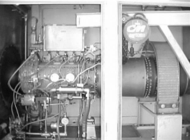
Ceramic Vane/Metal Mount Demonstration
The first-stage ceramic vane Phase 1 field demonstration occurred at an Exxon natural gas processing plant near Mobile, Alabama. Three identical Rolls Royce Allison Model 501-KB5 turbine skids provided power and process steam at this Exxon plant. Figure 15–30 shows one of the turbines in its skid enclosure at Exxon. The turbine with the ceramic first-stage vanes was installed and operated under normal commercial service conditions at maximum continuous power, except for preplanned teardowns and ceramic vane assembly inspections with removal of vanes for analyses. These inspections were originally scheduled at 200, 500, and 1000 hr. The turbine sustained power and performance throughout its operation with ceramic vanes. The turbine at Exxon experienced an emergency shutdown (the highest vane stress condition) at 525 hr and a full power water wash of its compressor with no detectable adverse effects on further operation or the ceramic vanes. The cause of the emergency shutdown was a malfunctioning vibration sensor and was unrelated to the ceramic vane assembly. There was no need to shut the turbine down associated with the ceramic vanes except for the planned inspections. None of the ceramic vanes failed or cracked and the metal mount design was shown to perform successfully. As mentioned earlier, a few vanes experienced chipping at platform edges, which appeared to alleviate local contact loads and enable further operation for many hours without propagation of cracks or failure.
Analyses of the vanes removed during the periodic inspections showed unexpected rates of material loss due to oxidation of the silicon nitride ceramic in the turbine operation environment. These rates of materials loss were determined to be excessive for industrial turbine applications, which require part lifetimes of 20,000 hr and longer. Analyses of the vanes showed the need for additional measures (e.g., environmental coatings) to achieve industrial turbine lifetimes. Since the Phase 1 demonstration had achieved its objective of identifying redesign needs, this demonstration phase was discontinued after a total operation time of 815 hr (22 hr proof test and 793 hr demonstration) for the Exxon turbine with ceramic vanes.
Analyses of Ceramic Vanes
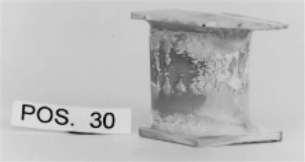
Visual evidence of ceramic oxidation was apparent during the turbine inspections. As illustrated by Figure 15–31, the color of the vanes had changed from tan/gray (vane on right) to white (vane on left). The ceramic vanes were covered by a white powder. The metal rotor blades and vanes in the two rows downstream of the ceramic vanes also had a dusting of white powder. The white powder was analyzed by Oak Ridge National Laboratory (ORNL) and found to be an oxide of silicon and lanthanum from the intergranular phase of the ceramic. Figures 15–32 and Figure 15–33 illustrate oxidation material losses visible to the unaided eye on vane concave and convex surfaces, respectively. These vanes had experienced 815 hr operation in the turbine.
Oxidation Versus Position in the Combustor Pattern
The trailing edge thickness was measured for each vane removed during inspections and after the demonstration to determine the oxidation loss of material at that location. Figure 15–34 shows trailing edge thickness losses at 815 hr versus radial location on the vanes and circumferential position in the six combustor cans of the turbine. The plot on the top shows thickness losses for vanes located at the same position at the exit of the combustor cans in the saddle region near the outside of the annular transition section from the combustor cans. The plot on the bottom shows thickness losses for vanes at the same location at the exit of the combustor cans near the center of the annular transition from the combustors. Both plots show losses at the hub, mid span, and tip trailing edge regions. These plots indicate that the greatest trailing edge losses were measured at the vane mid span, corresponding to the hottest and highest velocity location in the radial direction. The trailing edge losses were also higher at circumferential positions nearer to the center of the combustor outlet transition sections, again corresponding to higher temperatures and velocities. Similar circumferential patterns of trailing edge loss versus circumferential vane location were observed for the six combustors, but the overall level of loss varied by as much as a factor of 2 between combustors.
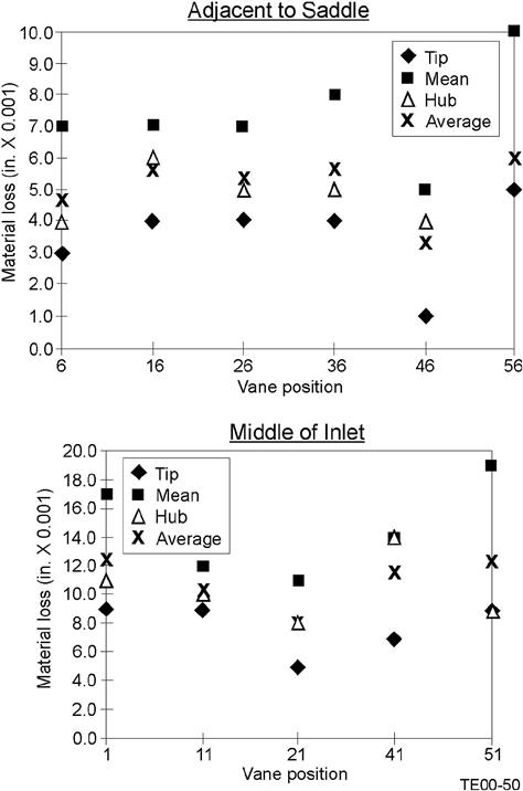
Oxidation Versus Time
Figure 15–35 shows the measured trailing edge losses at mid span (the trailing edge radial location of greatest loss) versus vane operation time in the turbine. The data suggest insignificant trailing edge thickness losses for times less than 200 hr. Analyses by ORNL identified an initial oxide scale on the new ceramic vanes resulting from processing. Apparently this scale was much more adherent and impermeable to further oxidant penetration to the underlying substrate than the oxide scale formed in the turbine environment. Figure 15–35 indicates that the two vanes removed after 222 hr of operation had very little measurable trailing edge material losses when compared to the pretest measurements. However, the vanes removed after 522 hr had measured trailing edge material losses up to 0.32 mm (0.0125 in.). Since the test was discontinued after the 815 hr inspection, all 60 vanes removed from the assembly were measured for trailing edge thickness losses. Except for vanes with low oxidation levels because of their locations in untypical flow and temperature regions behind the saddles, the decreases in trailing edge mid span thickness at 815 hr range from 0.13 mm (0.005 in.) to a maximum loss of 0.61 mm (0.024 in.). Percentage decreases in trailing edge thickness range from 12% to 50% of original values. The trailing edge thickness measurements indicated that the rate of oxidation might have been decreasing with time.
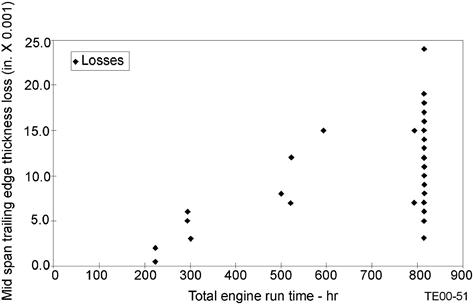
Oxidation Versus Position on Airfoil Surface
AlliedSignal took profile measurements of several of the ceramic vanes that had operated 815 hr in the turbine and compared those to profiles measured on the same vanes after fabrication. Figure 15–36 gives the mid span profile comparisons for one of the vanes that had the greatest material loss. Although the gas velocity near the airfoil surface varies from near zero at the nose stagnation point to about 573 m/s (1880 ft/sec) at the trailing edge, the loss does not greatly differ over the airfoil surface. This suggests that gas velocity is a secondary factor in the rates of oxidation and that relatively expensive high velocity rigs (e.g., cascades) might not be needed for ceramic materials oxidation tests. However, such ceramic materials tests do need to replicate the water vapor content and pressures of the turbine flow path environments.
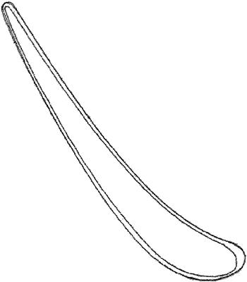
Retained Strength of Ceramic Vanes
Several of the ceramic vanes removed at various operation intervals from the demonstration turbine were sent to ORNL for retained strength measurements. Small disks (about 6 mm diameter and about 0.6 mm thick) were cut from the vanes and then fractured using a load at their center. Figure 15–37 shows results of the ORNL retained strength measurements versus operation time. The retained strength after 22 hr exposure to the turbine environment (in the engine proof test) increased over the as-processed strengths (zero time exposure). The average retained strength of specimens did not greatly change from initial values for increasing exposure times up to 815 hr, although the scatter in the strength measurements did increase with time. The lowest retained strength measurement in Figure 15–37 of about 500 MPa is approximately 2.4 times greater than the maximum calculated vane stress of 207 MPa at the highest stress vane location and worst (emergency shutdown) condition (see earlier discussion of stress analyses). Consequently, the ORNL data suggest that the vane oxidation is a surface phenomenon that does not substantially affect the strength of the underlying substrate material. Much longer vane lifetimes appear possible if the loss of surface material by oxidation can be inhibited (e.g., through use of environmental coatings).
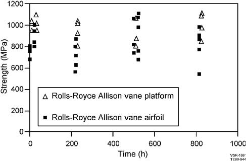
In summary, a first-stage ceramic vane and metal mount design has been developed and demonstrated for 815 hr under commercial industrial turbine conditions. This design appears to have successfully addressed many of the challenges of integrating stationary structural ceramics with metallics in an industrial turbine. However, the ability to operate a turbine for extended durations afforded by the ceramic vane/mount design has brought to light the issue of excessive long-term ceramic oxidation in the industrial turbine flow path environment. Additional measures are needed to improve materials durability so that commercial lifetimes of at least 20,000 hr can be achieved for industrial turbine ceramic parts. Measures to inhibit surface oxidation should advance structural ceramics toward this life goal since the strength of the ceramic structure underlying the oxidizing and recessing surfaces exposed to the flow stream was not observed to be markedly decreasing.
Case Study 3 describes the assessment of ceramic versus metal media filters for gas turbine power systems (conducted by Siemens Westinghouse).
Case Study 3: Assessment of Ceramic and Metal Media Filters in Advanced Power Systems9
Siemens Westinghouse Power Corporation (SWPC) has been involved in hot gas filter materials technology development since 1988. Emphasis was initially focused on the development and use of oxide- and nonoxide-based monolithic filter materials in bench-scale test programs and field applications (Table 15–5). With thermal fatigue issues being encountered by the oxide-based monoliths, and the oxidation and/or high temperature creep issues resulting in the nonoxide-based filter matrices during pressurized fluidized-bed combustion (PFBC) and/or pressurized circulating fluidized-bed combustion (PCFBC) operation, development of fracture toughened, continuous fiber reinforced ceramic composites (CFCC) and intermetallic filter elements was undertaken in 1994. Several issues were identified with respect to the long-term durability, response, and performance of the CFCC filter elements during extended service life. These included manufacturing and structural integrity, load bearing capability, and ease of fixturing within the filter system.
TABLE 15–5
Porous Ceramic and Metal Filter Technology Development [15-4]
| Monolithic Matrices | Fiber-Reinforced Composites | Metals/Intermetallics |
| Coors P-100A-1 alumina/mullite Pall clay-bonded silicon carbide (442T, 326, 181) Schumacher clay-bonded silicon carbide (F40, FT20) GTE cordierite and cordierite-silicon nitride AiResearch reaction bonded and sintered silicon nitride Enstomullite-bonded alumina Blasch mullite-bonded alumina Specific surface cordierite IF&P recrystallized silicon carbide Vacuum infiltrated chopped fibers IF&P fibrosics™ Foseco aluminosilicate Reticulated foam Ultramet CVI-SiC Selee oxide-based foam |
McDermott oxide-based CFCC Techniweave oxide-based CFCC 3M oxide-based CFCC Americon oxide-based CFCC 3M CVI-SiC DuPont SiC-SiC Textron nonoxide-Based CFCC Filament wound Honeywell PRD-66 |
US Filter Haynes 214, 556, 188, 230 Inconel 600, Hastelloy X, 3105 (US Filter, Pall, Mott Corp.) Iron aluminide (US Filter, Pall) FeCrAIY (US Filter, Technetics, others) |
Numerous advancements continued to be made since initiating development and manufacture of the monolithic and composite ceramic filters in 1988 and 1994, respectively. These included:
• Development and use of high temperature, creep resistant binders in the clay-bonded silicon carbide filter materials
• Efforts by alternate domestic and foreign suppliers (i.e., Blasch, Ensto, etc.) to bring to the market potentially viable filter materials and/or filter elements manufactured by alternate processes and production techniques
• Development of alternate filter concepts (i.e., sheet filter; inverted candle filter; etc.).
• Development of oxidation resistance coatings for nonoxide matrices
• Incorporation of a membrane along the o.d./i.d. surfaces of the filter elements
As issues arose with respect to the long-term viability of monolithic and CFCC filter elements, efforts were directed in 1998 to the development of a more robust, metal-based filter element.
Note: Table 15–6 provides a summary of the operating hours accumulated for each candle filter type tested in the various programs.
TABLE 15–6
Field and Extended Life Testing [15-4]
| Maximum Operating Time, hrs | Equivalent Exposure Time, hrs | ||
| Filter Supplier & Matrix | PFBC—AEP | PCFBC—FW Karhula | Field & Accelerated Testing |
| Schumacher F40 | 5855 | 227(1) | |
| Schumacher FT20 | 1705 | 2201(2) | 11,080; 11,080 |
| Pall Vitropore 442T | 1705 | 1341(1) | |
| Pall 326 | 2201(2) | 9662; 11,080 | |
| Coors P-100A-l alumina/mullite | 2815 | 716(1) | |
| 2201(2) | 8485; 12,211 | ||
| 3311(3) | 13,356 | ||
| 3M CVI-SIC | 1705 | 627(4) | |
| DuPont PRD-66 | 1705 | 581(5) | 7517(6) |
| 3M oxide CFCC | |||
| McDermott oxide CFCC | 581(5) | 10,626 | |
| Techniweave oxide CFCC | |||
| Blasch mullite-bonded alumina | 581(5) | 10,626 | |
| Ensto | |||
| IF&P REECER | 581(5) | 5611 | |
| Other | 5030(6) | ||
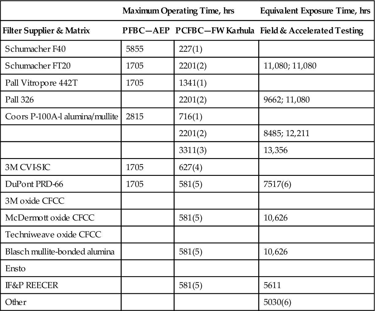
(1) 1992–1994 test campaign.
(2) 1995–1997 test campaign.
(3) 2201 hrs of operation under PCFBC conditions and 1110 hrs of operation under PFBC conditions.
(4) 1995–1996 test campaign.
(5) 1997 test campaign.
(6) New element without field exposure.
Ceramic Filter Elements—Summary Comments
Table 15–7 identifies the manufacturing, as well as thermal, mechanical, and chemical degradation, issues that have been identified during the initial and extended stages of life of the oxide and nonoxide-based, monolithic ceramic, fiber reinforced, and filament wound filter materials. Although microstructural changes occur in the porous ceramic filter matrices as a result of exposure to process operating conditions, the residual strength of all materials tends to stabilize after an initial conditioning period. An area that remains to be addressed is whether microstructural or phase changes will continue to occur within the various filter matrices with extended aging of elements during field operation, and whether continued phase change will impact the residual strength, thermal and/or mechanical properties, and filtration characteristics of the various filter materials. Continued grain growth and secondary phase formations are projected for some materials during extended field operation, which may have a significant impact on the ultimate viability of these filter elements during commercial operation.
TABLE 15–7
Matrix/Component Response to Process Operation—PFBC/PCFBC [15-4]
| Initial Life | |||
| Matrix Operating Time | Plant Commissioning | 1 Year | Extended Life > 3 Years |
| Monoliths | |||
| Oxides | Failure resulting from process thermal transients | Thermal fatigue Matrix phase changes; component conditioning |
Full matrix crystallization Microcrack formation Plant process control required for material/component stability and performance |
| Nonoxides | Failure resulting from extreme process thermal transients Initial matrix oxidation ≥700°C |
Matrix phase changes; component conditioning Impact of reformulation of binder phase limiting high temperature creep TBD Oxidation ≥700°C |
Crystallization of binder/ligaments Oxidation of SiC grains creep TBD Limited to <700–750°C applications |
| Fiber Reinforced | |||
| Oxides | Potential stability and performance issues related to manufacturing, homogeneity, and reproducibility of elements; lower strength; lower load bearing capabilities; and fixturing need to be addressed Oxidation >700°C Fiber/SiC bonding and embrittlement; reduced matrix fracture toughness |
Fiber embrittlement TBD | |
| Nonoxides | Initial oxidation >700°C Fiber/SiC bonding and embrittlement |
Potential stability and performance issues related to manufacturing, homogeneity, and reproducibility of elements; lower strength; lower load bearing capabilities; and fixturing need to be addressed Oxidation >700°C Fiber/SiC bonding and embrittlement; reduced matrix fracture toughness |
Not recommended for high temperature oxidizing applications |
| Filament Wound | |||
| Oxides | Potential stability and performance issues related to manufacturing, homogeneity, and reproducibility of elements; lower strength; lower load bearing capabilities; fixturing and membrane stability (devoting, matrix pull-out) need to be addressed | TBD | |
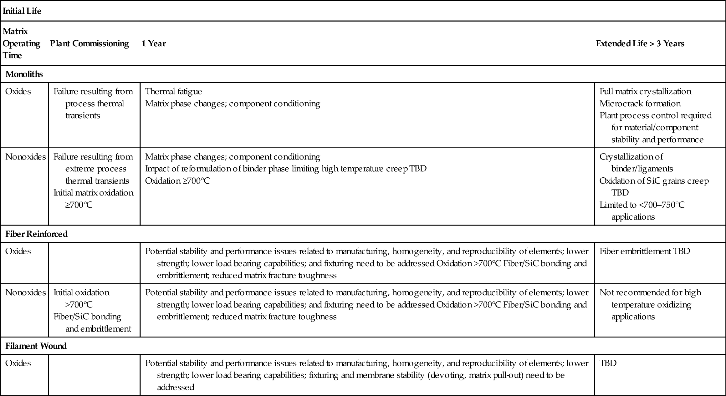
Metal Filter Media Development
In 1998, SWPC initiated a program with DOE/NETL to develop and evaluate the use of porous, high temperature, metal media candle filters in PFBC systems. Working with US Filter/Fluid Dynamics, Pall Advanced Separation Systems, Mott Corporation, Fairey Microfiltrex, Technetics, and Ultramet, SWPC produced composite filter elements for exposure to a simulated 1200°F (650°C), 1400°F (760°C), and 1550°F (840°C) PFBC process gas environment containing 200 ppmv S02/S03. The advanced alloys selected by SWPC for enhanced corrosion resistance in this environment were Haynes 230, 214, 188, and 556, and FeCrAIY. Elements constructed from 310S, Inconel 600, Hastelloy X, and FeAI were included as commercially available materials for comparison of performance in this program.
The filtration media of the advanced alloy filter elements principally included metal fibers, powders, wire laminates, and open-cell, metal-based, reticulated foams. Typically the US Filter/Fluid Dynamics, Fairey Microfiltrex, and Technetics sinter bonded fiber-containing metal media is formed into an ∼1 mm thick filtration mat layer which is supported by an underlying, dense, perforated, cylindrical metal support structure. An open mesh outer containment layer is included either along the outer surface of the porous filter body, encapsulating the filtration mat layer, or is embedded within, as well as sintered bonded to one surface of the porous filtration mat layer. The outer confinement mesh and filtration mat are generally longitudinally welded together, forming a tight fit around the underlying support structure. In contrast, filter elements fabricated from sinter bonded metal media powder or particulates typically are seamless (with the exception of Pall Hastelloy X), are generally thicker walled in comparison to fiber-containing metal filter elements, and do not have an outer confinement layer or underlying metal support structure.
The as-manufactured, high temperature, tensile strength of the commercially available and developmental porous advanced metal filter media are shown in Figure 15–38. Post-test exposure strength of the composite elements after 250 and 500 hours of simulated PFBC testing at 1200°F (650°C) is also shown. In general, the tensile strength of the as-manufactured US Filter/Fluid Dynamics filter elements at 1200°F (650°C) is between 10,000 and 17,000 psi. The strength of the fiber-containing US Filter/Fluid Dynamics filter media generally appeared to increase during the initial 250 hours of exposure to the simulated PFBC operating conditions. After 500 hours of exposure, a minor reduction in the 1200°F (650°C) tensile strength resulted for the advanced US Filter/Fluid Dynamics filter media, as well as Hastelloy X, while a continued strengthening of the commercially available 310S and Inconel 600 filter media resulted. Minor strengthening of the Mott Inconel 600 and Pall FeAI powder-containing media, and Fairey Microfiltrex fiber-containing media resulted during initial operation in the 1200°F (650°C) simulated PFBC environment. In contrast, the 1200°F (650°C) tensile strength of the powder-containing Pall 310 and Hastelloy X porous filter media decreased as a function of operating time. Due to the variation in the use of coarse vs. fine outer containment mesh, trends in the Technetics residual tensile strength were not readily apparent for the porous FeCrAIY filter media. Currently testing is ongoing at SWPC STC to demonstrate the potential viability of the various porous filter media during 1400°F (760°C) simulated PFBC operation.