Queues are important parts of any real-time operating system. Queues are used for intertask communication in real-time operating systems. They can be used to send messages and data between tasks, and between interrupts and tasks. A queue is basically a FIFO (First In First Out) type buffer such that new data is sent to the back of the queue and the first data that is sent to the queue is the first one that is received by the receiving task. Notice that in FreeRTOS it is possible to send data to the front of the queue. You may think a queue to be like a table having only one row but many columns. This Chapter is about creating a queue and sending and receiving data using queues. Several real-time and multitasking tested projects are given in the Chapter using FreeRTOS queue functions.
Keywords
FreeRTOS
Clicker 2 for STM32
mikroC Pro for ARM
using global variables
queues
creating a queue
queue handle
sending data via a queue
receiving data via a queue
message waiting
resetting a queue
10.1. Overview–global variables
In the last chapter, we have developed several FreeRTOS based projects, each project having multiple tasks. You will notice that in those projects we used global variables (variables declared at the beginning of a program before any task) to pass data between tasks. Although global variables can be safe and easy to use in small programs, in general, it is not recommended to use global variables in complex programs because of the following reasons:
• Global variables can be changed by any part of the code, for example, by any task in a multitasking environment. This can make it difficult to keep track of these variables.
• Using global variables causes very tight coupling of code.
• Global variables have no access control.
• Testing a program using global variables can be very difficult as it is difficult to decouple them.
• If global variables can be accessed by multiple tasks at the same time, then synchronization of these tasks may be required.
There are no problems of using global variables in small programs as long as these global variables names are prefixed by some letters so that they cannot be mixed with local variables with similar names. For example, instead of using Cnt as a global variable, use GblCnt instead.
10.2. Why queues?
Queues are important parts of any multitasking operating systems. Queues are used for intertask communication in multitasking operating systems. They can be used to send messages and data between tasks and between interrupt service routines and tasks. It is recommended to use queues instead of global variables in complex programs when it is required to pass data or messages between tasks in a multitasking program. A queue is basically a FIFO (First In First Out) type buffer such that new data is sent to the back of the queue and the first data that is sent to the queue is the first one that is received by the receiving task. Notice that in FreeRTOS it is possible to send data to the front of the queue. You may think a queue to be like a table having only one row but many columns. Data is put into the table columns from the left and extracted from the right. For example, consider a queue having four storage cells. Assuming that numbers 2, 4, 6, and 8 are put into the queue, the queue will look like in Fig. 10.1
Figure 10.1A queue with 4 cells.
In FreeRTOS, messages are passed to queues by copy which means that the data itself is copied into the queue and not the reference to the data. As a result of this, the data is available for re-use. The kernel allocates memory for the use of queues. Small messages and data (e.g., characters, integers, small structures, etc.) can be sent into a queue directly without having to allocate buffer for them. Large data can be passed to a queue by defining a queue to hold pointers and copy just a pointer to the message into the queue. A single queue can be used to receive different message types, and messages from multiple locations, by defining the queue to hold a structure that has a member that holds the message type, and another member that holds the message data.
In this chapter, we shall be looking at the various FreeRTOS queue functions and see how they can be used in application programs. Only the commonly used queue functions are described in this Chapter. Interested readers can get further details on all available queue functions from the following link:
10.3. Creating a queue, sending and receiving data using queues
The API function xQueueCreate() is used to create a new queue. The RAM memory required by the queue is automatically allocated by the kernel. The format of this function is:
xQueue: The handle of the queue from which the data is being received (read). The queue handle will have been returned from the call to xQueueCreate().
pvBuffer: A pointer to the memory into which the received data will be copied to. The length of the buffer must be at least equal to the queue item size. The item size will have been set by the uxItemSize parameter of the call to xQueueCreate().
xTicksToWait: This is the maximum amount of time the task should remain in the Blocked state to wait for data to become available on the queue, if the queue is empty. If xTicksToWait is zero, then xQueueReceive() will return immediately if the queue is already empty.The block time is specified in tick periods, the pdMS_TO_TICKS() macro can be used to convert a time specified in milliseconds to a time specified in ticks. Setting xTicksToWait to portMAX_DELAYwill cause the task to wait indefinitely (without timing out) provided INCLUDE_vTaskSuspend is set to 1 file FreeRTOSConfig.h.
Return values
pdPASS: Returned if data was successfully read from the queue. If a block time was specified (xTicksToWait was not zero), then it is possible that the calling task was placed into the Blocked state, to wait for data to become available on the queue, but data was successfully read from the queue before the block time expired.
errQUEUE_EMPTY: Returned if data cannot be read from the queue because the queue is already empty. If a block time was specified (xTicksToWait was not zero) then the calling task will have been placed into the Blocked state to wait for another task or interrupt to send data to the queue, but the block time expired before this happened
API functions xQueueSend() and xQueueSendToBack() are identical and they both send (write) data to the back of a queue. Function xQueueSendToFront() sends data to the front of a queue.
Parameters
xQueue: The handle of the queue to which the data is being sent (written). The queue handle is returned from a call to create a queue.
pvItemToQueue: A pointer to the data to be copied into the queue. The size of each item the queue can hold is set when the queue is created, and that many bytes will be copied from pvItemToQueue into the queue storage area.
xTicksToWait: The maximum amount of time the task should remain in the Blocked state to wait for space to become available on the queue, should the queue already be full.
xQueueSend(): xQueueSendToFront() and xQueueSendToBack() will return immediately if xTicksToWait is zero and the queue is already full. The block time is specified in tick periods. The pdMS_TO_TICKS() macro can be used to convert a time specified in milliseconds to a time specified in ticks. Setting xTicksToWait to portMAX_DELAYwill cause the task to wait indefinitely (without timing out), provided INCLUDE_vTaskSuspend is set to 1 in file FreeRTOSConfig.h.
Return values
pdPASS: Returned if data was successfully sent to the queue. If a block time was specified (xTicksToWait was not zero), then it is possible that the calling task was placed into the Blocked state, to wait for space to become available in the queue before the function returned, but data was successfully written to the queue before the block time expired.
errQUEUE_FULL: Returned if data could not be written to the queue because the queue was already full. If a block time was specified (xTicksToWait was not zero) then the calling task will have been placed into the Blocked state to wait for another task or interrupt to make room in the queue, but the specified block time expired before that happened.
An example project is given in the next section to shows how a queue can be created in practise and how inter-task communication can take place using this queue.
10.4. Project 21–changing LED flashing rate from the PC keyboard
Description: This project is similar to Project 16 described in Chapter 9, where global variable called FlashRateMs was received from the PC keyboard and it was used as the delay parameter to change the LED flashing rate. In this program, a queue is created instead of using a global variable, and the LED flashing rate is passed to the task controlling the LED using this queue. There are two tasks in this project in addition to the Idle task.
Aim: The aim of this project is to show how a queue can be created and data can be sent from one task to another one using this queue.
Block diagram: The block diagram of this project is same as in Fig. 9.43, but here additionally the LED at port PE12 is used. The USB UART Click board is plugged to mikroBUS socket 2 of the Clicker 2 for STM32 development board as in Project 16.
Program listing:Fig. 10.2 shows the program listing (program: QueueLED.c). The program consists of two tasks excluding the Idle task. The queue handle is named xQueue and is passed to both tasks as task parameters during the creation of the tasks. Task 1 is created as shown below:
Figure 10.2QueueLED.c program listing.
xTaskCreate(
(TaskFunction_t)Task1,
“UART Controller”,
configMINIMAL_STACK_SIZE,
(void*)xQueue,
10,
NULL
);
The queue length (QueueLength) was set to 1 since only one variable was to be sent via the queue. The queue size (QueueSizeBytes) was set to 8 since the variable was a long which consists of 8 bytes. The operation of the two tasks are summarized below:
Task 1
This is the UART Controller task. At the beginning of the task the queue handle is obtained from the task parameter, UART 3 uses ports PD8 and PD9 of the development board and it is initialized to operate at 9600 baud as in project 16. Then, the user is prompted to enter the required flashing rate and the following text is displayed on the PC screen
Enter LED Flash Rate (Seconds):
The program reads the flashing rate from the PC keyboard as numeric data and stores the total number in seconds in variable called Total. The user entry is terminated when the Enter key is pressed on the keyboard. Variable Total is then converted into milliseconds by multiplying by 1000. The value of this variable is then sent to the queue using the following statement. The parameter xTicksToWait is set to 10ms so that the task will be in Blocked state for 10ms if there is no space available in the queue:
xQueueSend(xQueue, &Total, pdMS_TO_TICKS(10));
The following text is then displayed on the PC screen to confirm that the flashing rate has changed:
Flashing Rate Changed...
Task 2
This task implements the LED flashing function. At the beginning of the task the queue handle is obtained from the task parameter. The flashing rate is stored in variable called FlashRateMs and this variable is set to 1000ms at the beginning by default. The LED keeps flashing as the user enters data from the keyboard. The flashing rate is read from the queue as follows. The data read from the queue is stored in variable FlashRateMs:
xQueueReceive(xQueue, &FlashRateMs, 0);
Parameter xTicksQueueWait is set to 0 so the function call will return immediately if there is no data in the queue. The value read by the queue function is used in function vTaskDelay() as the new flashing rate of the LED.
As you can see from Fig. 10.2, all the variables used in both tasks are local to their tasks and global variables are not used in the program. Although using global variables may seem to be an easier option in this case, it has the disadvantages outlined at the beginning of this Chapter in section 10.1.
Fig. 10.3 shows a typical run of the program where the flashing rate was set to 3 seconds.
Figure 10.3Setting the flashing rate to 3 seconds.
10.5. Deleting a queue, name of a queue, resetting a queue
The API function xQueueDelete() deletes a queue that has been created earlier. A queue must not be deleted if there are any tasks currently blocked on it. The format of the function is:
vQueueDelete(TaskHandle_t pxQueueToDelete);
Parameters
pxQueueToDelete: This is the handle of the queue being deleted.
Return value
The function has no return value
The API function pcQueueGetName() returns the text formatted name of a queue. A queue will only have a text name if it has been added to the queue registry using function vQueueAddToregistry() described later. The format of this function is:
pcQueueGetName(QueueHandle_t xQueue);
Parameter
xQueue: This is the handle of the queue being queried.
Return value
Queue names are standard NULL terminated C strings. The value returned is a pointer to the name of the queue being queried.
The API function vQueueAddToRegistry() assigns a name to a queue and adds the name to the queue registry. The format of this function is:
xQueue: This is the handle of the queue that will be added to the queue registry.
pcQueueName: A descriptive name for the queue. Notice that queue names are not used by FreeRTOS in any way and they are intended as debugging aids since identifying a queue by its name is much easier than attempting to identify by its handle.
Return value
The function has no return values
The parameter configQUEUE_REGISTRY_SIZE defines the maximum number of queues and semaphores (we will see later) that can be registered at any one time. This parameter must be greater than 0 to and item to the queue registry.
The API function xQueueReset() resets a queue to its original state. Any data in the queue at the time of the function call is discarded. The format of the function is:
xQueueReset(QueueHandle_t xQueue);
Parameter
xQueue: This is the handle of the queue that is being reset.
Return values
pdPASS or pdFAIL is returned.
10.6. Project 22—using various queue functions
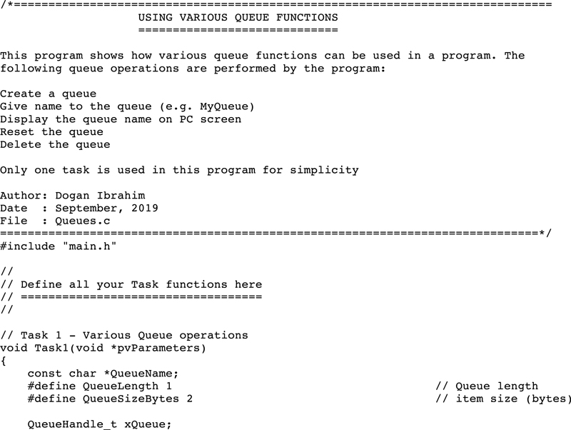
Description: This project shows how some of the queue functions described in Section 10.5 can be used in an application program. Only one task is used in this project. The following queue operations are performed by the program:
• Create a queue
• Give a name to the queue
• Display the queue name on PC screen
• Reset the queue
• Delete the queue
Aim: The aim of this project is to show how various queue functions can be used in a program.
Block diagram: The block diagram of this project is same as in Fig. 9.43. The USB UART Click board is plugged to mikroBUS 2 socket of the Clicker 2 for STM32 development board as in Project 16.
Program listing: Fig. 10.4 shows the program listing (program: Queues.c). The program consists of one task in addition to the Idle task. At the beginning of the program the queue length and queue size are defined, and UART is initialized to operate at 9600 baud. The message Various queue operations is then displayed on the PC screen. Following this, a queue is created and it is added to the queue registry with the name MyQueue. The program then gets the queue name by calling function pcQueueGetName() and stores in variable pointed to by QueueName. The queue name is then displayed on the PC screen by sending to the UART. Finally, the queue is reset and then deleted.
Figure 10.4Queues.c program listing.
Fig. 10.5 shows the output from the program, displayed using the Putty terminal emulation program.
Figure 10.5Output from the program.
10.7. Some other queue functions
The API function xQueueOverwrite() writes to the queue even if the queue is full. It is intended to be used for queues having lengths of one (the queue is empty or full). The format of the function is:
xQueue: This the handle of the queue to which the data is to be sent.
pvItemToQueue: A pointer to the item that is to be placed in the queue.
Return value
xQueueOverwrite() is a macro that calls xQueueGenericSend(), and therefore has the same return values as xQueueSendToFront(). However, pdPASS is the only value that can be returned because xQueueOverwrite() will write to the queue even when the queue is already full.
The API function xQueuePeek() reads an item from the queue, it does not remove the item from the queue. The format of this function is:
xQueue: This is the handle of the queue from which data is to be read.
pvBuffer: A pointer to the memory into which the data read from the queue will be copied to.
xTicksToWait: The maximum amount of time the task should remain in the Blocked state to wait for data to become available on the queue, should the queue already be empty. If xTicksToWait is zero,then xQueuePeek() will return immediately if the queue is already empty. The block time is specified in tick periods, the pdMS_TO_TICKS() macro can be used to convert a time specified in milliseconds to a time specified in ticks. Setting xTicksToWait to portMAX_DELAY will cause the task to wait indefinitely (without timing out) provided INCLUDE_vTaskSuspend is set to 1
Return values
pdPASS: Returned if data was successfully read from the queue.
errQUEUE_EMPTY: Returned if data cannot be read from the queue because the queue is already empty. If a block time was specified (xTicksToWait was not zero) then the calling task will have been placed into the Blocked state to wait for another task or interrupt to send data to the queue, but the block time expired before this happened.
The API function uxQueueSpacesAvailable() returns the number of free spaces available in the queue. The format of this function is:
xQueue: This is the handle of the queue being queried.
Returned value
The number of items that are held in the queue at the time of the function call.
10.8. Project 23—ON-OFF temperature controller
Description: In this project we design an ON-OFF temperature control project based on a multitasking approach. An ON-OFF temperature controller, also known as a bang-bang controller, will turn OFF the heater whenever the temperature is above a pre-defined setpoint (i.e., the required value). Similarly, if the temperature is below the setpoint then the heater is turned ON. ON-OFF controllers are used for simplicity since there is no need to know the model of the plant to be controlled. The only parameter that need to be set is the setpoint value. ON-OFF control is suitable when the response delay of the plant to be controlled is short and the output rate of rise time is small. If precision temperature control is required, then it may be more appropriate to use professional PID (Proportional + Integral + Derivative) type controller algorithms with negative feedback, or to use an intelligent fuzzy-based controller. The problem with most professional controllers is that an accurate model of the plant to be controlled is normally required before a suitable control algorithm can be derived. ON-OFF type controller has the disadvantage that the relay used to turn the heater ON and OFF has to operate many times and this may shorten the life of the relay.
Aim: The aim of this project is to show how an ON-OFF type controller can be designed using a multitasking based approach.
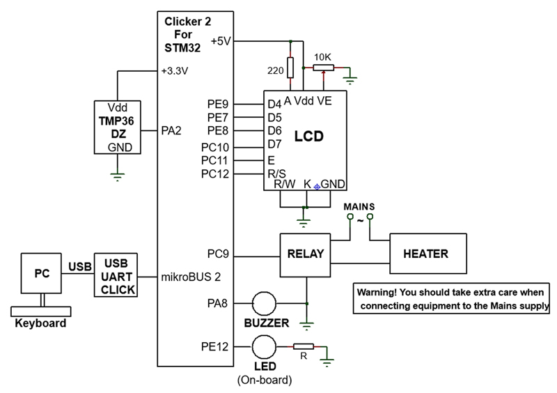
Block diagram: The block diagram of this project is shown in Fig. 10.6. The following components are used in this project in addition to the Clicker 2 for STM32 development board:
• USB UART Click board
• Analog temperature sensor chip
• LCD
• 10K potentiometer for LCD contrast adjustment
• Buzzer
• Relay
• Heater
• Keyboard (with a PC)
Figure 10.6Block diagram of the project.
In this project it is required to control the temperature of an oven using ON-OFF type controller. The setpoint temperature is entered using a keyboard connected to a PC. This setpoint value can be changed at any desired time while the oven is under control. i.e. there is no need to stop the controller in order to change the setpoint value (hence multitasking). A relay connected to the Clicker 2 for STM32 development board turns the heater ON or OFF under the control of software. An LCD connected to the development board displays the setpoint temperature as well as the actual measured oven temperature. The temperature of the oven is measured using an analog temperature sensor chip. A buzzer is used which becomes active if the temperature of the oven goes above a dangerous preset value to indicate an alarm condition. An LED displays the state of the oven at any time such that when the oven is ON then the LED is ON, and vice-versa.
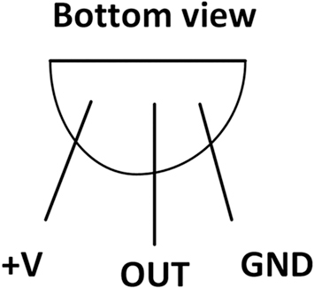
Circuit diagram: A 16 × 2 character LCD is connected to the development board as described in previous projects in Chapter 9. The TMP36DZ type temperature sensor chip is used in this project. This is a small 3-pin chip that has the following basic specifications:
The relay used in the design is a standard relay that can operate with +3.3 V and it is assumed that the relay contacts can switch the mains supply ON or OFF with the heater connected to it. The buzzer is a standard low voltage (+3.3 V) active device that sounds when a logic 1 is applied to its +V input. The on-board LED connected to port pin PE12 is used to indicate the status of the oven (an external LED can be connected to the development board if desired).
The circuit diagram of the project is shown in Fig. 10.8. The interface between the Clicker 2 for STM32 development board and the external components are as follows:
Clicker 2 for STM32 pin
External component pin
Mode
PE9
LCD pin D4
Digital output
PE7
LCD pin D5
Digital output
PE8
LCD pin D6
Digital output
PC10
LCD pin D7
Digital output
PC11
LCD pin E
Digital output
PC12
LCD pin R/S
Digital output
PC9
Relay
Digital output
PE12
LED (on-board)
Digital output
PA2
TMP36DZ
Analog input
PA8
Buzzer
Digital output
Figure 10.8Circuit diagram of the project.
Program listing: The program consists of 4 tasks excluding the Idle task. All the tasks are configured to run at the same priority:
Task 1
Main task
Task 2
UART controller
Task 3
LCD controller
Task 4
Buzzer controller
At the beginning of the program, the interface between the LCD and the development board is defined. Three queues are used in this program with the following handles (these handles are defined as global in this program for simplicity):
Queue handle
Description
Used by Tasks
xUARTQueue
UART queue
Task 1, Task 2
xLCDQueue
LCD queue
Task 1, Task 3
xBuzzerQueue
Buzzer queue
Task 1, Task 4
The descriptions of the tasks are given below.
Task 1
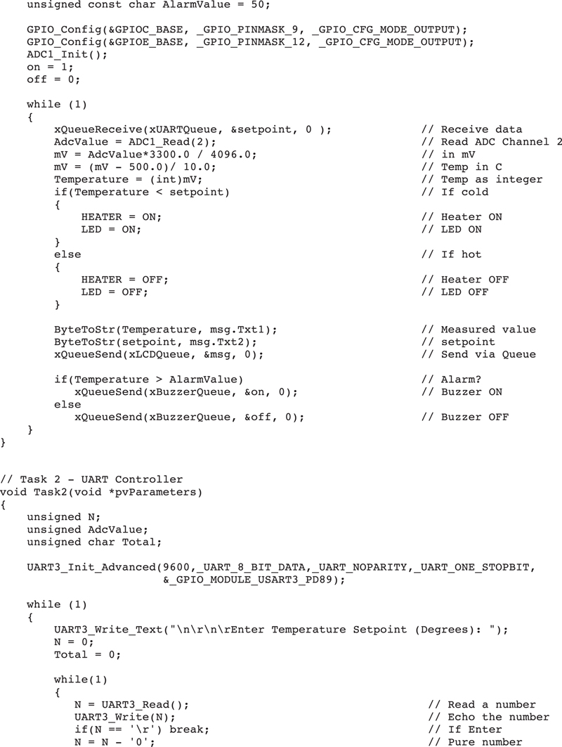
This is the main task that controls the oven temperature. This task reads the analog temperature from the TMP36DZ temperature sensor chip which is connected to Channel 2 (port pin PA2) of the microcontroller. By default, at the beginning of this task the setpoint is set to 30°C and the alarm value is set to 50°C respectively. New setpoint values are received through the xUARTQueue from Task 2. The relay at port pin PC9 is configured as an output and also the LED at port pin PE12 is configured as an output. The temperature is read by calling the built-in ADC function ADC1_Read(2) where 2 is the channel number. The ADC on the microcontroller is 12-bits wide, thus having 4096 quantization levels. The reference voltage of the ADC is 3.3 V (3300 mV). The analog value read from Channel 2 is converted into physical millivolts by multiplying it by 3300 and dividing by 4096. The absolute temperature of the TMP36DZ is found by measuring its output voltage in millivolts, subtracting 500, and then dividing by 10, that is,
T = (Vo − 500)/10
where T is the absolute temperature in °C and Vo is the output voltage of the sensor chip in millivolts. If the measured temperature is less than the setpoint then the relay is activated to turn ON the heater. If on the other hand the measured temperature is greater than the setpoint then the relay is de-activated to turn OFF the heater. The measured temperature is compared with the pre-defined alarm value and if it is higher than the alarm value, then a 1 is sent to Task 4 (Buzzer Controller) using the xBuzzerQueue so that Task 4 activates the buzzer. If the measured temperature is less than the alarm value, then a 0 is sent to Task 4 to stop the buzzer. The measured and the setpoint temperature values are sent to the LCD via the xLCDQueue so that they can be displayed on the LCD. A structure is created to store the measured and the setpoint temperature values in character arrays Txt1 an Txt2 respectively. Both arrays have 4 cells since the built-in function ByteToStr() converts a byte into a string with 4 characters, including leading spaces.
Task 2
This is the UART Controller task. At the beginning of this task, UART is initialized to operate at 9600 baud. The message Enter Temperature Setpoint (Degrees): is displayed on the PC screen using the Putty terminal emulation software. The required setpoint value (in integer) is read from the keyboard and is sent to Task 1 through xUARTQueue. Then the message Temperature setpoint changed… is displayed on the PC screen. Fig. 10.9 shows the message displayed by this task where the setpoint temperature was set to 45°C.
Figure 10.9Message displayed by Task 2.
Task 3
This is the LCD Controller task. At the beginning of this task the LCD is initialized, display is cleared, and the cursor is set to be OFF so that it is not visible. The task receives the measured and the setpoint temperature values through queue xLCDQueue in the form of a structure. Character arrays Txt1 and Txt2 store the measured and the setpoint temperature values respectively. The LCD display is refreshed every second. Fig. 10.10 shows the LCD display.
Figure 10.10The LCD display.
Task 4
This is the Buzzer Controller task. At the beginning of this task, port pin PA8 is configured as output. The task receives the buzzer state through the queue xBuzzerQueue. If 1 is received, then an alarm condition is assumed and the buzzer is activated. If on the other hand 0 is received, then the buzzer is de-activated.
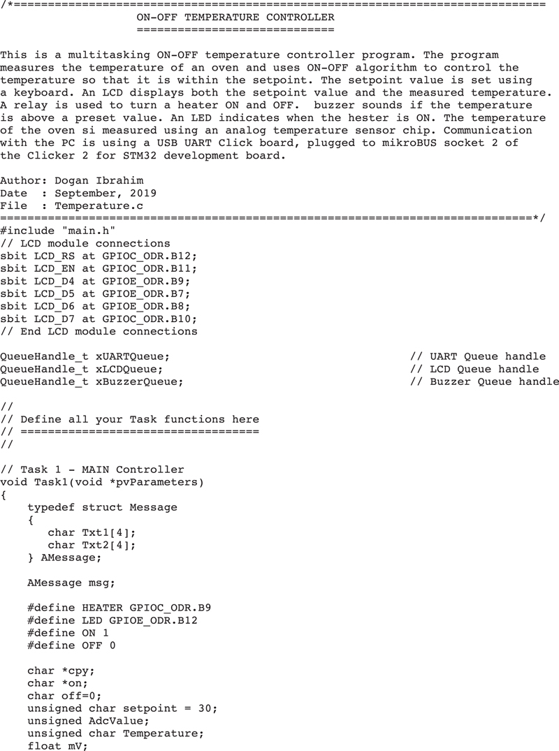
Fig. 10.11 shows the program listing (program: Temperature.c).
Figure 10.11Temperature.c program listing.
The operation of the program is summarized in the Program Description Language (PDL) shown in Fig. 10.12.
Figure 10.12Operation of the program.
Notice that the following items must be enabled in the Library Manager of mikroC Pro for ARM compiler before the program is compiled:
• ADC
• Conversions
• C_String
• C_Stdlib
• Lcd
• Lcd_Constants
• UART
10.9. Summary
Queues are used for inter-communication between tasks in a multitasking program. In this chapter, we have learned how to use the various FreeRTOS queue functions in application programs developed as multitasking projects.
In the next chapter, we shall be looking at the Semaphores and Mutexes and see how they can be used for synchronization purposes in application programs in multitasking projects.