Event groups allow events to be communicated to tasks and they allow a task to wait in the blocked state for a combination of one or more events to occur. Event groups unblock the tasks that is waiting for the same event, or combination of events, when the event occurs. Event groups therefore can be used to synchronize tasks, allowing a task to wait in blocked state for any one of a set of events to occur. Event groups can be used in many applications to replace semaphores with a single event group, thus reducing the RAM usage. This chapter is about creating, deleting, setting, and clearing event groups and event flags. The FreeRTOS event group API functions are given and explained in the chapter. This chapter describes in detail and with fully tested projects how to create and use event groups and event flags in real time multitasking projects.
Keywords
FreeRTOS
mikroC Pro for ARM
Clicker 2 for STM32
event group
event flag
creating an event group
deleting an event group
setting and clearing event flags
GPS
GPS sentences
NMEA
latitude and longitude
12.1. Overview
Event groups allow events to be communicated to tasks and they allow a task to wait in the blocked state for a combination of one or more events to occur. Event groups unblock the tasks that is waiting for the same event, or combination of events, when the event occurs. Event groups therefore can be used to synchronize tasks, allowing a task to wait in blocked state for any one of a set of events to occur.
Event groups can be used in many applications to replace semaphores with a single event group, thus reducing the RAM usage. Notice that event groups are an optional part of FreeRTOS and source file FreeRTOS/source/event_groups.c must be compiled as part of your program. Also the header file event_groups.h must be included at the beginning of your program.
12.2. Event flags and event groups
An event flag, also called an event bit, is a one bit value (0 or 1) used to indicate if an event has occurred or not. Sets of event flags make an event group. An event group holds the state of all the event flags belonging to that group. The state of an event flag is represented by a variable of type EventBits_t. When an event bit is set, it is said that the event represented by that bit has occurred.
Event groups are stored in variables of type EventGroupHandle_t. Event groups can be accessed by any task in the system, and any number of tasks can set or read the bits in an event group. The number of bits (or flags) within an event group is 8 if parameter configUSE_16_BIT_TICKS is set to 1, or 24 if parameter configUSE_16_BIT_TICKS is set to 0 (the default setting) in the configuration file. An event flag inside an event group is identified by its bit position. For example, bit 0 is event flag 0, bit 20 is event flag 20, and so on. If for example an event group holds the hexadecimal value 0x92, then event flags 1, 4, and 7 are set (0x92 = “1001 0010” in binary). The programmer gives meanings to the event flags. For example, bit 0 may represent that the task is waiting for a message, bit 3 may mean that the LED has been turned ON and so on.
In the remainder parts of this chapter, we shall be looking at some of the commonly used event group API functions of FreeRTOS, and also give a practical project to show how event groups can be used in a multitasking project.
Interested readers can find further information on event groups at the following web sites:
The API function xEventGroupCreate() is used to create an event group. The handle of the created event group is returned to the calling program. The format of the function is:
xEventGroupCreate(void);
The function has no parameters.
Return values
Null: The event group could not be created because there was insufficient FreeRTOS heap available.
Any other value: The event group was created and the value returned is the handle of the created event group.
The API function vEventGroupDelete() is used to delete a previously created event group. Tasks that are blocked on the event group being deleted will be unblocked. The format of the function is:
xEventGroupHandle_t: The handle of the event group to be deleted.
The function has no return value.
12.4. Setting, clearing, waiting For event group bits, and getting event group bits
The API function xEventGroupSetBits() is used to set the event flags within an event group. Setting an event flag will unblock a task that is waiting for that flag to be set. The format of the function is:
xEventGroup: The handle of the event group in which the bits are to be set. The event group must have previously been created.
uxBitsToSet: A bitwise value that indicates the bit or bits to set in the event group.
Return values
Any value: The value of the bits in the event group at the time the call to xEventGroupSetBits() returned. There are two reasons why the returned value might have the bits specified by the uxBitsToSet parameter cleared:
1. If setting a bit results in a task that was waiting for the bit leaving the blocked state, then it is possible the bit will have been cleared automatically (see the xClearBitsOnExit parameter of xEventGroupWaitBits()).
2. Any task that leaves the blocked state as a result of the bits being set (or otherwise any Ready state task) that has a priority above that of the task that called xEventGroupSetBits() will execute and may change the event group value before the call to xEventGroupSetBits() return
The API function xEventGroupClearBits() is used to clear event flags within an event group. The format of the function is:
xEventGroup: The event group in which the bits are to be cleared. The event group must have previously been created using a call to xEventGroupCreate().
uxBitsToClear: A bitwise value that indicates the bit or bits to clear in the event group.
Return values
All values: The value of the bits in the event group before any bits were cleared
The API call xEventGroupWaitBits() is used to enter a blocked state (with a timeout) if the specified event flag or flags are not set. The format of the function is:
xEventGroup: The event group in which the bits are being tested.
uxBitsToWaitFor: A bitwise value that indicates the bit or bits to test inside the event group. For example, to wait for bit 0 and/or bit 2 set uxBitsToWaitFor to 0x05.
xClearOnExit: If xClearOnExit is set to pdTRUE then any bits set in the value passed as the uxBitsToWaitFor parameter will be cleared in the event group before xEventGroupWaitBits() returns if xEventGroupWaitBits() returns for any reason other than a timeout. The timeout value is set by the xTicksToWait parameter. If xClearOnExit is set to pdFALSE then the bits set in the event group are not altered when the call to xEventGroupWaitBits() returns.
xWaitAllBits: xWaitForAllBits is used to create either a logical AND test (where all bits must be set) or a logical OR test (where one or more bits must be set) as follows:If xWaitForAllBits is set to pdTRUE then xEventGroupWaitBits() will return when either all the bits set in the value passed as the uxBitsToWaitFor parameter are set in the event group or the specified block time expires. If xWaitForAllBits is set to pdFALSE then xEventGroupWaitBits() will return when any of the bits set in the value passed as the uxBitsToWaitFor parameter are set in the event group or the specified block time expires.
xTicksToWait: The maximum amount of time to wait (in ticks) for one/all (depending on the xWaitForAllBits value) of the bits specified by uxBitsToWaitFor to become set.
Return values
Any value: The value of the event group at the time either the event bits being waited for became set, or the block time expired. The current value of the event bits in an event group will be different to the returned value if a higher priority task or interrupt changed the value of an event bit between the calling task leaving the blocked state and exiting the xEventGroupWaitBits() function. Test the return value to know which bits were set. If xEventGroupWaitBits() returned because its timeout expired then not all the bits being waited for will be set. If xEventGroupWaitBits() returned because the bits it was waiting for were set then the returned value is the event group value before any bits were automatically cleared in the case that xClearOnExit parameter was set to pdTRUE.
The API function xEventGroupGetBits() is used to return the current values of the event flag bits in an event group. The format of the function is:
xEventGroup: The event group being queried. The event group must have previously been created using a call to xEventGroupCreate().Return ValuesAll values. The value of the event bits in the event group at the time xEventGroupGetBits() was called.
12.5. Project 25—sending internal and external temperature data to a PC
Description: This project is similar to Project 24 given in the previous chapter. In this project, two analog temperature sensor chips are used: a temperature sensor to measure the temperature inside an oven, and another temperature sensor to measure the ambient temperature outside the oven. There are three tasks in the project in addition to the Idle task. The external and internal temperatures and are read by the two tasks and this data is sent to another task which displays the data on the PC screen. In this project both the external and the internal temperatures are displayed every 2 seconds. In this program event flags are used instead of a mutex to synchronize the access to the UART. By setting, clearing, and waiting on event flags we make sure that only one task accesses the UART at any time.
Aim: The aim of this project is to show how event flags can be used to synchronize shared access to the UART.
Block diagram: The block diagram of this project is as in Fig. 11.1.
Circuit diagram: The circuit diagram of the project is as in Fig. 11.2, where, two LM35DZ analog temperature sensor chips are used to measure the temperature inside and outside an oven. Connection to the PC is through a mini USB cable connected between the USB UART Click board.
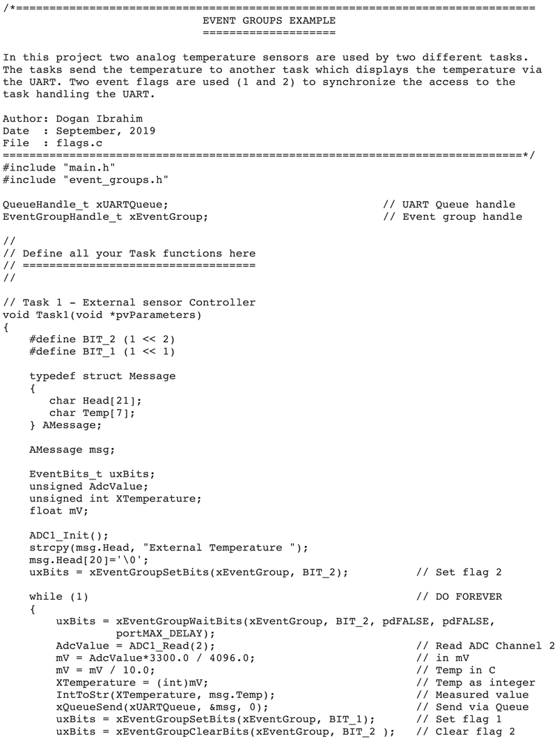
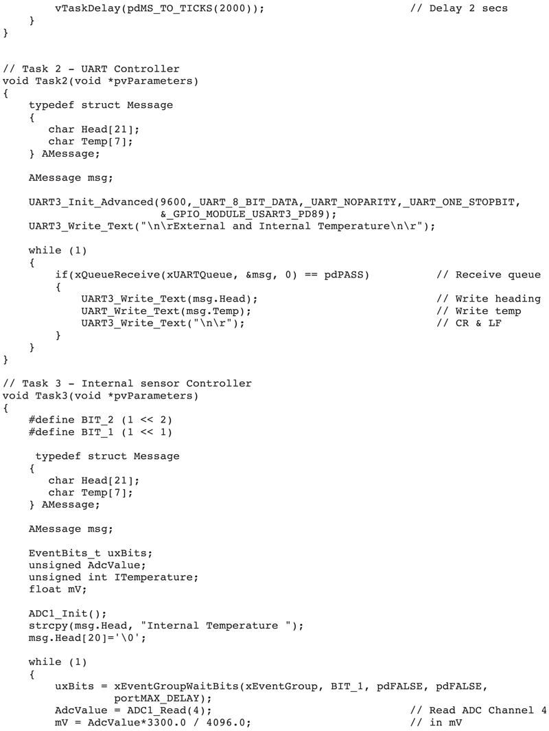
Program listing: The program listing is shown in Fig. 12.1 (program: flags.c). There are three tasks in the system, in addition to the Idle task. Inside the main program, an event group is created with the handle xEventGroup. Bits 1 and 2 of this event group are used in the program. The operation of the program is described in the following PDL where Task 1 and Task 3 send their temperature readings to the UART controller in Task 2 through a queue:
Figure 12.1flags.c program listing.
Main
Create Queue with handle xUARTQueue
Create event group with handle xEventGroup
Task 1
Task 3
Task 2
Set event flag 2
DO FOREVER
Wait for event flag 2
Send Data via queue
Set event flag 1
Clear event flag 2
ENDDO
DO FOREVER
Wait for event flag 1
Send data via queue
Set event flag 2
Clear event flag 1
ENDDO
DO FOREVER
IF data in Queue THEN
Send data to UART
ENDIF
ENDDO
The details of each task are described in detail below.
Task 1
This is the External temperature task. The task reads the ambient analog temperature from sensor LM35DZ, converts the reading into millivolts, and then converts it to °C by dividing it with 10. In this task, analog input port PA2 of the Clicker 2 for STM32 development board is used. The reading is then converted into a string using the built-in function IntToStr() and sent to the UART. The task then sets event flag 1 and clears event flag 2 before exiting.
The following statement is used to set event flag 2:
uxBits = xEventGroupSetBits(xEventGroup, BIT_2);
Similarly, the following statement is used to clear event flag 2:
Notice here that the task is blocked waiting forever until event flag 2 is set. Also, the xCLEAROnExit parameter is set to pdFALSE so that the flag is not cleared when function xEventGroupWaitBits() exits. We could have set this parameter to pdTRUE so that event flag 2 would be cleared automatically on exit from the function. This way, there would not be need to clear event flag 2 explicitly in Task 1.
Task 3
This task is similar to Task 1, but here the internal oven temperature is read and sent to UART. Analog port PA4 of the Clicker 2 for STM32 development board is used.
Task 2
This is the UART controller task. At the beginning of the task, the UART is initialized to operate at 9600 baud. The task then checks the queue and reads the message if there is one. The message consists of two parts: a heading and the measured temperature. The message is sent to UART which is displayed on the PC screen via a terminal emulation software.
12.6. Project 26—controlling the flashing of an LED
Description: This is a very simple project. In this project the LED on the Clicker 2 for STM32 development board at port PE12 is used. Two tasks are used in the project in addition to the Idle task. The LED is flashed in a task every second after receiving a command from the keyboard in another task. Entering command ON sets an event flag which starts the LED flashing. Similarly, entering OFF clears the event flag and this causes the LED to turn OFF. A USB UART Click board is connected to mikroBUS 2 socket of the Clicker 2 for STM32 development board as in the previous project and the PC is connected to this board using a mini USB cable. A terminal emulation software is used on the PC to enter commands through the keyboard and to display the messages on the screen.
Aim: The aim of this project is to show how event groups (or event flags) can be used to synchronize shared access to a resource.
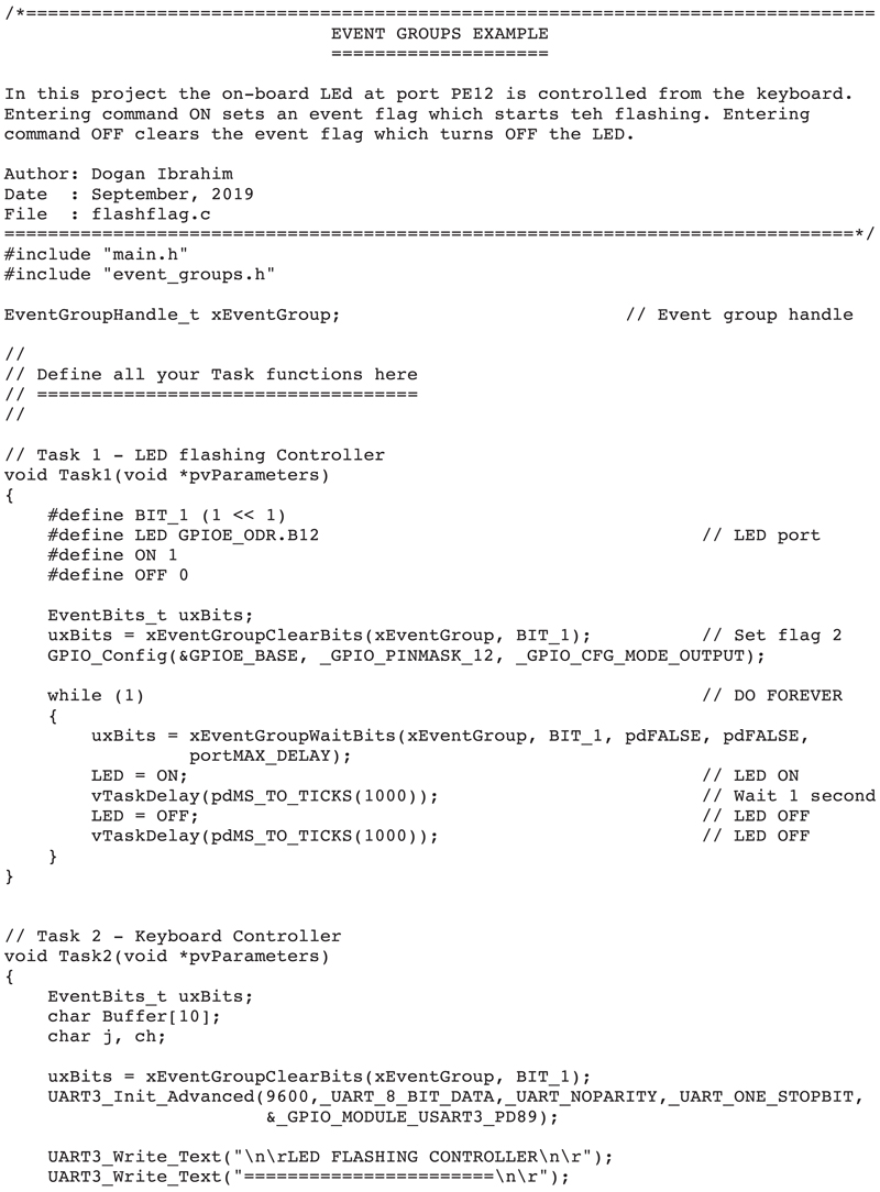
Program listing: The program listing is shown in Fig. 12.2 (program: flashflag.c). There are 2 tasks in the system, in addition to the Idle task. Inside the main program, an event group is created where event flag 1 is used. Task 2 prompts the user to enter a command from the keyboard. If command ON is entered then event flag 1 is set. If on the other hand command OFF is entered then event flag 1 is cleared. Task 1 flashes the LED every second whenever the event flag 1 is set. Clearing event flag 1 stops the LED flashing. At the beginning of the program the LED is configured to be OFF. The operation of the program is demonstrated by the following PDL:
Main
Create an event group
Clear event flag 1
Task 2
Task 1
DO FOREVER
Read a command from the keyboard
IF command is ON THEN
Set event flag 1
ELSE IF COMMAND is OFF THEN
Clear event flag 1
ENDIF
ENDDO
Turn OFF LED
DO FOREVER
IF event flag 1 is set THEN
Flash the LED
ELSE
Turn OFF the LED
ENDIF
ENDDO
Figure 12.2flashflag.c program listing.
Commands are received from the keyboard using the UART3_Read() statement as shown below. If UART is ready (i.e., it has received a character) then the character is read into character variable ch. The character read is then echoed on the screen so that the user can see the entered character. If the character is the Enter key then the program exits the loop. Otherwise, the received character is stored in Buffer and the buffer index is incremented:
Description: In this project a GPS receiver module is used to get the local latitude and longitude data from the GPS satellites. This data is read by a task every second and is sent to another task which controls a UART. The data is displayed on the PC screen. An LED is used to indicate whether or not the received data is valid (i.e., the GPS has received valid data from the satellites). The LED flashes if the received GPS data is valid, otherwise it is turned OFF.
Aim: The aim of this project is to show how event flags and queues can be used in a project. Also, it is shows how data can be received from a GPS receiver and how it can be decoded to extract the latitude and the longitude.
Block diagram: Fig. 12.4 shows the project block diagram. A GPS Click board (see www.mikroe.com) is connected to mikroBUS 1 socket of the Clicker 2 for STM32 development board. The GPS Click board is based on the u-blox LEA-6S GPS chip. The board is designed to run on a +3.3V power supply and communicates with the target microcontroller through UART or I2C interfaces. In this project, the UART interface is used for simplicity. The baud rate of the board is set to 9600 by default. GPS Click board can simultaneously track up to 16 satellites and has a TTFF (time to first fix) of less than one second. An external antenna is recommended if the GPS is used indoors as it may not be possible to receive signals from the GPS satellites. Additionally, a USB UART Click board is connected to mikroBUS 2 socket as in the previous project. A mini USB cable connects the USB UART Click board to the PC. The on-board LED connected to port pin PE12 is used to indicate the data validity.
Figure 12.4Block diagram of the project.
When the USB UART Click board is plugged in to mikroBUS 2 socket, it connects to UART3 at port pins PD8 and PD9 of the development board. Similarly, when the GPS click board is plugged in to microBUS 1 socket, it connects to UART2 at port pins PC5 and PC6 of the development board.
Program listing: There are three tasks in the system, in addition to the Idle task. Inside the main program, an event group and also a queue are created. Task 1 flashes the LED at a fast rate of 250 milliseconds if the received GPS data is valid. Task 2 receives the latitude and longitude from Task 3 and displays on the PC screen whenever valid data is received. The operation of the program is summarized with the following PDL statements:
Task 1
DO FOREVER
Wait for event flag 1 to be set
Flash the LED at a rate of 250ms
ENDDO
Task 2
DO FOREVER
Wait for event flag 2 to be set
Receive data from the queue
Display Latitude/Longitude
ENDDO
Task 3
DO FOREVER
Extract Latitude/Longitude from the GPS
IF data is valid THEN
Set event flags 1 and 2
Send Latitude/Longitude to the queue
ELSE
Clear event flags 1 and 2
ENDIF
ENDDO
The details of each task are given below.
Task 1
This is the simplest task in the program which controls the LED. At the beginning of the task loop the task waits for event flag 1 to be set. This flag is set by Task 3 if it receives valid GPS data. The task flashes the LED every 250 ms if valid data is received from the GPS by Task 3. If valid data is not received by the GPS then the LED stays OFF.
Task 2
This is the UART controller task. The task waits until event flag 2 is set which indicate that valid data has been received by Task 3. The latitude and longitude data are then read from the queue sent by Task 3. The data is received into a structure called msg which has the following format:
typedef struct Message
{
char LatitudeString[11];
char LatitudeDirection[2];
char LongitudeString[12];
char LongitudeDirection[2];
} AMessage;
UART3 is initialized to 9600 baud rate at port pins PD8 and PD9. The latitude and longitude are displayed starting from row 3, column 0 of the PC screen. The terminal emulation program is set to type VT100 where the cursor is controlled by various escape sequences. The following cursor control was used in this task:
The above character array gotoscr positions the cursor at row 3, column 0. Similarly, character array clrscr clears the screen. In general, the cursor position can be set to row n, column m by the following escape sequence:
<esc>[n;mH
Task 3
This is the task which reads the GPS data from the GPS receiver and extracts the local latitude and longitude. LEA-6S type GPS receiver is used on the GPS Click board. This GPS receives data from the GPS satellites and sends out data in text form from its serial port. This data is also known as the NMEA sentences. LEA-6S sends out the NMEA sentences shown in Fig. 12.5. Each NMEA sentence starts with a $ character and the values in the sentence are separated by commas. Some of the NMEA sentences returned by the GPS Click board are given below:
Figure 12.5NMEA sentences.
$GPGLL: This sentence returns the local geographical latitude and longitude
$GPRMC: This sentence returns the local geographical latitude and longitude, speed, track angle, date, time, and magnetic variation.
$GPVTG: This sentence true track, magnetic track, and the ground speed.
$GGGA: This sentence returns the local geographical latitude and longitude, time, fix quality, number of satellites being tracked, horizontal dilution of position, altitude, height of geoid, and DGPS data
$GPGSV: There are four sentences with this heading. These sentences return the number of satellites in view, satellite number, elevation, azimuth, and SNR.
In this task, $GPGLL sentence is used to get the geographical latitude and longitude. This sentence has the following fields:
$GPGLL,4916.45,N,12311.12,W,225444,A,*1D
Where:
GLL
Geographic position, Latitude and Longitude
4916.46,N
Latitude 49 deg. 16.45 min. North
12311.12,W
Longitude 123 deg. 11.12 min. West
225444
Fix taken at 22:54:44 UTC
A
Data Active or V (void)
*iD
checksum data
Notice that the fields are separated by commas. The validity of the data is shown by letters A or V in the data where A shows that the data is valid, and V indicates that the data is not valid.
The program uses the statement UART2_Read_Text(Buffer, “GPGLL”, 255) to wait until the string GPGLL is received. The program waits until the starting character $ is received before waiting to receive GPGLL. This makes the task run faster so that it is not interrupted by the scheduler while reading the GPS data (i.e., not context switched). If we use the statement UART2_Read_Text(Buffer, “$GPGLL”, 255) then the task may spend time waiting and thus may be interrupted by another task, causing part of the data not to be read properly. This may require the priority of the task to be higher than the priority of other tasks in the program.
The program looks for commas in the complete $GPGLL sentence and extracts the latitude, direction of latitude, longitude, direction of latitude, and the character indicating the validity of the data. If the received GPS data is valid then event flags 1 and 2 are set and the Latitude/Longitude data are sent to the queue. If on the other hand the data is not valid then event flags 1 and 2 are cleared. The task waits for 10 seconds before it continues.
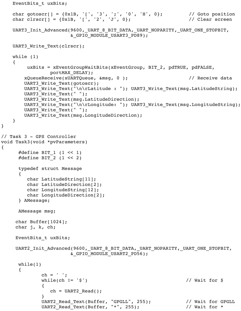
The program listing is shown in Fig. 12.6 (program: gps.c). Fig. 12.7 shows the Latitude and Longitude displayed at row 3, column 0 of the screen.
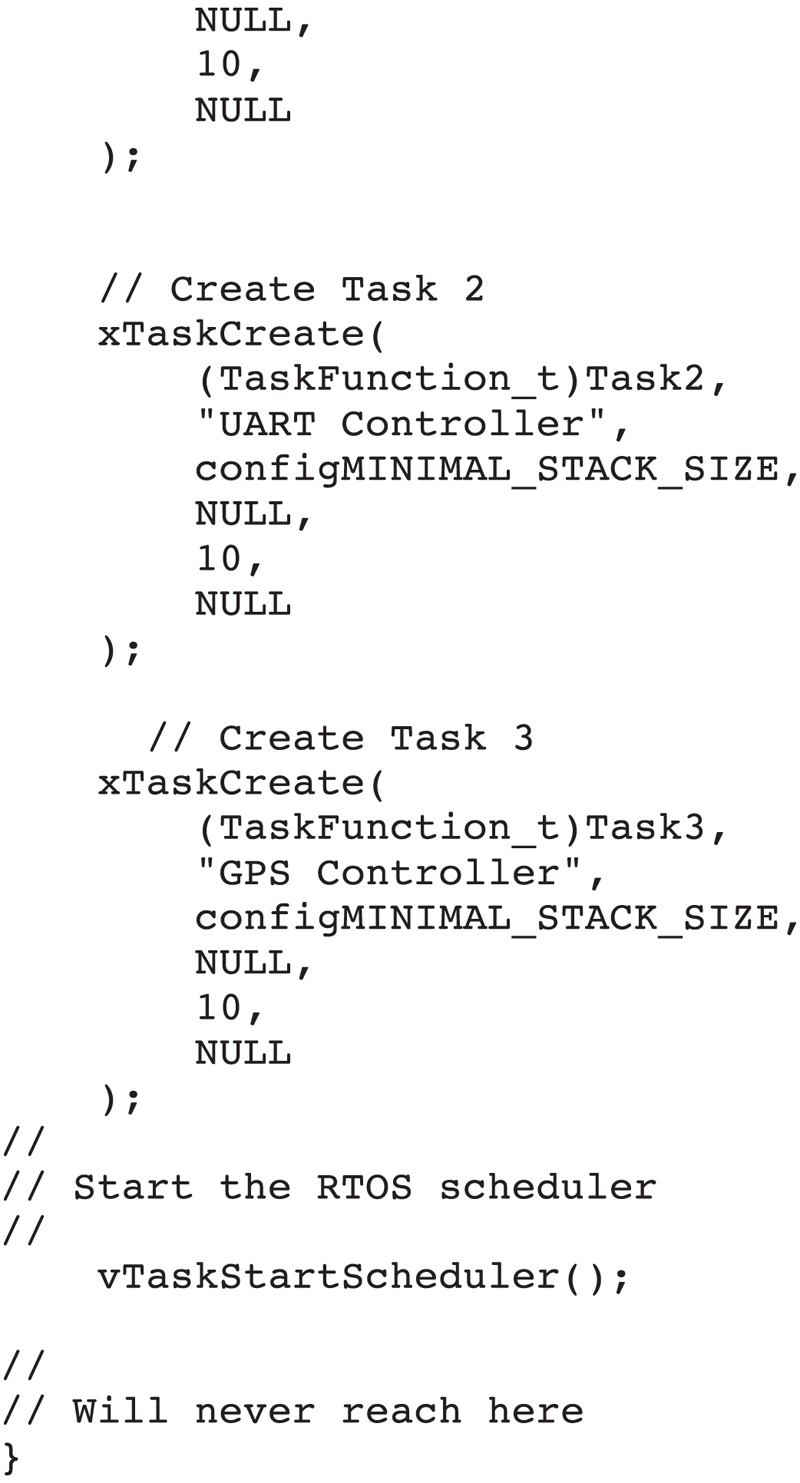
Figure 12.6gps.c program listing.
Figure 12.7Displaying the latitude and longitude.
Fig. 12.8 shows the Clicker 2 for STM development board together with the USB UART Click board and the GPS Click board.
Figure 12.8Project components.
12.8. Summary
In this chapter, we have learned the concept of event groups and event flags. Two practical projects are given in the chapter to show how the event flags can be used in a multitasking project.
In the next chapter, we shall be looking at the FreeRTOS software timers and learn how the timers can be used in practical projects.