Software timers are important parts of any real-time operating system. The timers are used in tasks to schedule the execution of a function at a time in the future, or periodically with a fixed frequency. Software timers under FreeRTOS do not require any hardware and are not related to hardware timers as they are implemented in software. When a timer expires the program can be configured to call a function called the timer’s callback function. A timer must be created before it can be used. Timers must be started, stopped, or reset manually by the user programs. Software timer API functions send commands from the calling task to the daemon task on a queue called the “timer command queue.” This chapter is about creating, deleting, resetting, and stopping software timers. Also, this chapter gives several working and tested real time multitasking projects using the FreeRTOS software timer functions.
Keywords
FreeRTOS
Clicker 2 for STM32
mikroC Pro for ARM
software timer
one-shot timer
auto-reload timer
creating and deleting a timer
stopping and resetting a timer
reaction timer
event counter
square waveform
13.1. Overview
Software timers are important parts of any real-time multitasking operating system. The timers are used in tasks to schedule the execution of a function at a time in the future, or periodically with a fixed frequency. Software timers under FreeRTOS do not require any hardware and are not related to hardware timers as they are implemented in software. When a timer expires, the program can be configured to call a function names as the timer’s callback function.
Software timers are optional in FreeRTOS and the application programs must be built with the source file FreeRTOS/Source/timers.c included as part of the program. Parameter configUSE_TIMERS must be set to 1 in file FreeRTOSConfig.h before the software timers can be used.
Two types of software timers are supported by FreeRTOS: One-shot, and Auto-reload.
One-shot timers: These timers are started manually and do not re-start when they complete. The callback function is executed only one when the timer expires.
Auto-reload timers: These timers re-start each time they expire, thus resulting in repetitive execution of the callback function attached to the timer.
A software timer can be in one of two states: Dormant, and Running. A Dormat timer exists but it is not active. A Running timer is active and it will call its callback function when its period expires.
All software timer callback functions execute in the context of the same RTOS daemon (or “timer service”) task. The daemon task is a standard FreeRTOS task that is created automatically when the scheduler is started. The priority and stack size are set at compile time by the two parameters in file FreeRTOSConfig.h: configTIMER_TASK_PRIORITY and configTIMER_TASK_STACK_DEPTH. Callback functions must not call to functions that may cause the enter the Blocked state.
A timer must be created before it can be used. Creating a timer does not start it. Timers must be started, stopped, or reset manually by the user programs. Software timer API functions send commands from the calling task to the daemon task on a queue called the “timer command queue.” The timer command queue is a standard FreeRTOS queue that is created automatically when the scheduler is started. The length of the timer command queue is set by the configTIMER_QUEUE_LENGTH compile time configuration constant in FreeRTOSConfig.h.
The daemon task is scheduled like any other FreeRTOS task and it will process commands, or execute timer callback functions, when it is the highest priority task that is able to run. Parameter configTIMER_TASK_PRIORITY controls the timer task priority.
Some of the important software timer API functions are given below. Interested readers can get further detailed information on software timers from the following web sites:
13.2. Creating, deleting, starting, stopping, and resetting a timer
The API function xTimerCreate() creates a timer and returns a handle to identify the created timer. Notice that creating a timer does not start it. The format of the function is:
pcTimerName: A plain text name that is assigned to the timer, purely to assist debugging.
xTimerPeriod: This is timer period, specified in multiples of tick periods. The pdMS_TO_TICKS() macro can be used to convert a time in milliseconds to a time in ticks. For example, if the timer must expire after 500ms, then the period can be set to pdMS_TO_TICKS(500), provided configTICK_RATE_HZ is less than or equal to 1000.
uxAutoReload: This parameter is set to pdTRUE to create an autoreload timer. When set to pdFALSE, a one-shot timer is created.
pvTimerID: An identifier that is assigned to the timer being created. The identifier can later be updated using the vTimerSetTimerID() API function. If the same callback function is assigned to multiple timers, then the timer identifier can be inspected inside the callback function to determine which timer actually expired.
pxCallbackFunction: This is the function to call when the timer expires. Callback functions must have the prototype defined by the TimerCallbackFunction_t typedef. An example prototype function is shown below:
Null: The software timer could not be created because there was insufficient FreeRTOS heap memory available to successfully allocate the timer data structures.
Any other value: The software timer was created successfully.
Parameters configUSE_TIMERS and configSUPPORT_DYNAMIC_ALLOCATION must both be set to 1 in file FreeRTOSConfig.h before this function can be used. If left unspecified, configSUPPORT_DYNAMIC_ALLOCATION is set to 1 by default.
The API function xTimerDelete() is used to delete a timer. The format of the function is:
xTicksToWait: Timer functionality is not provided by the core FreeRTOS code, but by a timer service (or daemon) task. The FreeRTOS timer API sends commands to the timer service task on a queue called the timer command queue. xTicksToWait specifies the maximum amount of time the task should remain in the Blocked state to wait for space to become available on the timer command queue, should the queue already be full. The block time is specified in tick periods, so the absolute time it represents is dependent on the tick frequency. The pdMS_TO_TICKS() macro can be used to convert a time specified in milliseconds to a time specified in ticks. Setting xTicksToWait to portMAX_DELAY will cause the task to wait indefinitely (without timing out), provided INCLUDE_vTaskSuspend is set to 1 in FreeRTOSConfig.h. xTicksToWait is ignored if xTimerDelete() is called before the scheduler is started.
Return values
pdPASS: The delete command was successfully sent to the timer command queue.
pdFAIL: The delete command was not sent to the timer command queue because the queue was already full.
The API function xTimerStart() starts a timer running. If the timer was already running, then xTimerStart() is functionally equivalent to resetting the timer.
xTimer: The timer to be reset, started, or restarted.
xTicksToWait: Timer functionality is not provided by the core FreeRTOS code, but by a timer service (or daemon) task. The FreeRTOS timer API sends commands to the timer service task on a queue called the timer command queue. xTicksToWait specifies the maximum amount of time the task should remain in the Blocked state to wait for space to become available on the timer command queue, should the queue already be full.
Return values
pdPASS: The start command was successfully sent to the timer command queue. If a block time was specified (xTicksToWaitwas not zero), then it is possible that the calling task was placed into the Blocked state to wait for space to become available on the timer command queue before the function returned, but data was successfully written to the queue before the block time expired. When the command is actually processed will depend on the priority of the timer service task relative to other tasks in the system,
pdFAIL: The start command was not sent to the timer command queue because the queue was already full.
The API function xTimerStop() stops a timer running. The format of the function is:
xTicksToWait: Timer functionality is not provided by the core FreeRTOS code, but by a timer service (or daemon) task. The FreeRTOS timer API sends commands to the timer service task on a queue called the timer command queue. xTicksToWait specifies the maximum amount of time the task should remain in the Blocked state to wait for space to become available on the timer command queue, should the queue already be full.
Return values
pdPASS: The stop command was successfully sent to the timer command queue.
If a block time was specified (xTicksToWait was not zero), then it is possible that the calling task was placed into the Blocked state to wait for space to become available on the timer command queue before the function returned, but data was successfully written to the queue before the block time expired.
pdFAIL: The stop command was not sent to the timer command queue because the queue was already full. If a block time was specified (xTicksToWait was not zero) then the calling task will have been placed into the Blocked state to wait for the timer service task to make room in the queue, but the specified block time expired before that happened.
The API function xTimerReset() resets a timer. If the timer is already running, then the timer will recalculate its expiry time to be relative to when xTimerReset() was called. If the timer was not running, then the timer will calculate an expiry time relative to when xTimerReset() was called, and the timer will start running. In this case, xTimerReset() is functionally equivalent to xTimerStart(). Resetting a timer ensures the timer is running. The format of the function is:
xTimer and xTicksToWait has the same functionality as in the function call xTimer- Stop().
Return values
The return values pdPASS and pdFAIL have the same functionality as in the call xTimerStop().
13.3. Change timer period, get timer period
This function changes the timer period. If the period of a timer that is already running is to be changed, then the timer will use the new period value to recalculate its expiry time. The recalculated expiry time will then be relative to when xTimerChangePeriod() was called, and not relative to when the timer was originally started. If xTimerChangePeriod() is used to change the period of a timer that is not already running, then the timer will use the new period value to calculate an expiry time, and the timer will start running. The format of this function is:
xTimer: The timer to which the new period is being assigned.
xNewPeriod: The new period for the timer. Timer periods are specified in multiples of tick periods. The pdMS_TO_TICKS() macro can be used to convert a time in milliseconds to a time in ticks.
xTicksToWait: This parameter has the same functionality as in the other timer functions.
Return values
The return values pdPASS and pdFAIL have the same functionality as in the call xTimerStop().
The API function xTimerGetPeriod() returns the period of a timer. The function has the format:
xTimerGetPeriod(TimerHandle_t xTimer);
Parameters
xTimer: The handle of the timer being queried.
Return values
The period of the timer, specified in ticks.
13.4. Timer name and ID
The function call pcTimerGetName() returns the name (in text format) assigned to the timer when the timer was created. The function has the following format:
pcTimerGetName(TimerHandle_t xTimer);
Parameters
xTimer: The timer being queried.
Return values
Timer names are standard NULL terminated C strings. The value returned is a pointer to the subject timer’s name.
The function call pvTimerGetTimerID() returns the identifier (ID) assigned to the timer when the timer was created.
pvTimerGetTimerID(TimerHandle_t xTimer);
Parameters
xTimer: The timer being queried.
Return values
The identifier assigned to the timer being queried.
13.5. Project 28—reaction timer
Description: This is a reaction timer project which makes use of an LED and a push-button switch. The user is expected to press the push-button switch as soon as the LED is turned ON. The time between the LED being turned ON and the user pressing the button is measured and displayed on an LCD in milliseconds. The LED is turned ON again after a random delay, ready for the next measurement.
Aim: The aim of this project is to show how the elapsed time can be measured. In this program a FreRTOS software timer is not used, but instead the xTaskGetTickCount() API function is used. Additionally, the project shows how to use the random function generator in a program to generate random numbers.
Block diagram: Fig. 13.1 shows the block diagram of the project. The on-board LED at port pin PE12 and the push-button switch at the on-board port pin PE0 are used in this project.
Figure 13.1Block diagram of the project.
Circuit diagram: The circuit diagram of the project is shown in Fig. 13.2. The LCD is connected to the Clicker 2 for STM32 development board as in the previous LCD based projects.
Figure 13.2Circuit diagram of the project.
Program listing: The operation of the program is described by the following PDL:
BEGIN
Configure the LCD
DO FOREVER
Wait 5 seconds
Wait random time between 1 and 10 seconds
Turn the LED ON
Save the current tick count
Wait until push-button switch is pressed
Save the new tick count
Calculate the elapsed time
Turn LED OFF
Display elapsed time in milliseconds on LCD
ENDDO
END
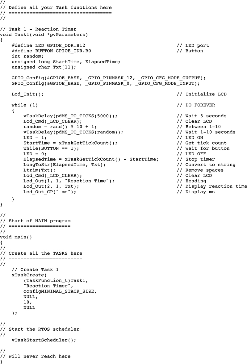
The program listing (program: reaction.c) is shown in Fig. 13.3. The program consists of only one task in addition to the Idle task. At the beginning of the program the interface between the LCD and the Clicker 2 for STM2 development board is defined, the LCD is initialized, port pin PE12 is configured as output, and PE0 is configured as input. The remainder of the task is executed in an endless loop. Inside this loop, built-in function rand() is called. This function generates a random integer number between 0 and 32767. An integer variable called random is used to limit the generated random numbers between 1 and 10. This value is then used to create random delay in the program so that the user does not know when the LED will lit. As soon as the LED is turned ON, the current tick count is stored in variable StartTime. The program then waits until the button is pressed by the user, and then calculates the elapsed time by getting the new tick count and subtracting the old tick count from it. This value is the reaction time of the user in milliseconds, which is then displayed on the LCD.
Figure 13.3reaction.c program listing.
Fig. 13.4 shows a typical display of the reaction time on the LCD.
Figure 13.4Reaction time displayed on the LCD.
13.6. Project 29—generate square waveform
Description: In this project an auto-reload FreeRTOS software timer is used to generate a positive square waveform signal with a frequency of 500 Hz, and equal ON and OFF times (i.e., 50% duty cycle). At 500 Hz, the ON and the OFF times of the waveform are 1ms each as shown in Fig. 13.5.
Figure 13.5Positive square waveform at 500 Hz.
Aim: The aim of this project is to show how a FreeRTOS software can be used to generate a square waveform signal.
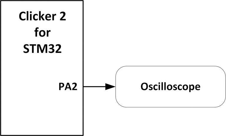
Circuit diagram: Fig. 13.6 shows the circuit diagram of the project. The waveform is generated at port pin PA2 of the Clicker 2 for STM32 development board. A digital oscilloscope is connected to this pin to display the generated waveform.
Figure 13.6Circuit diagram of the project.
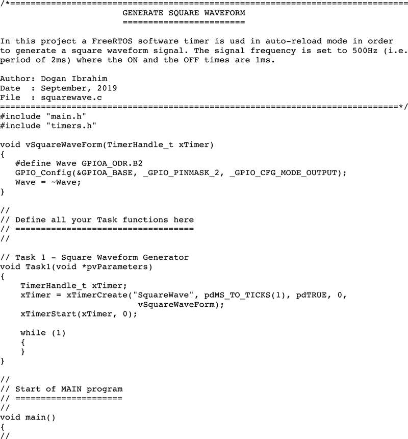
Program listing: The program listing (squarewave.c) is shown in Fig. 13.7. There is only one task in this program in addition to the Idle task. Variable Wave is assigned to port pin PA2. The program creates an auto-reload timer with a period of 1ms, using the following statement. The timer ID field is not used in this program:
The callback function called vSquareWaveForm is executed at the end of each timer period. In this function port pin PA2 is toggled every time so that a square waveform is generated at this pin.
Fig. 13.8 shows the waveform on an oscilloscope. In this project the Velleman PCSGU250 is used to display the waveform on the PC screen. In this figure the horizontal axis is 1 ms/div and the vertical axis is 1 V/div. Clearly, the duration of the ON and OFF times are 1 ms each, corresponding to a period of 2 ms, that is, the frequency is 500 Hz.
Figure 13.8Waveform generated by the program.
13.7. Project 30—event counter (e.g., frequency counter)
Description: In this project an auto-reload FreeRTOS software timer is used. The project counts the number of events occurring in a second. For example, the project can be used as a frequency counter to measure and display the frequency of an analog waveform. It is assumed that the input signal is in the form of positive square waveform. If the signal is a sine wave, then it will be required to convert it to a positive square wave using for example a Schmitt trigger logic gate, or a transistor switch.
Aim: The aim of this project is to show how a FreeRTOS software can be used to create a frequency counter (or event counter) project.
Block diagram: Fig. 13.9 shows the block diagram of the project. The measured frequency is displayed on an LCD.
Figure 13.9Block diagram of the project.
Circuit diagram: The circuit diagram of the project is similar to Fig. 13.2, but here the push-button and the LED are not used, but instead external events are applied to port pin PA2 of the development board. It is important to make sure that the input signal is positive and its magnitude is not greater than +3.3 V.
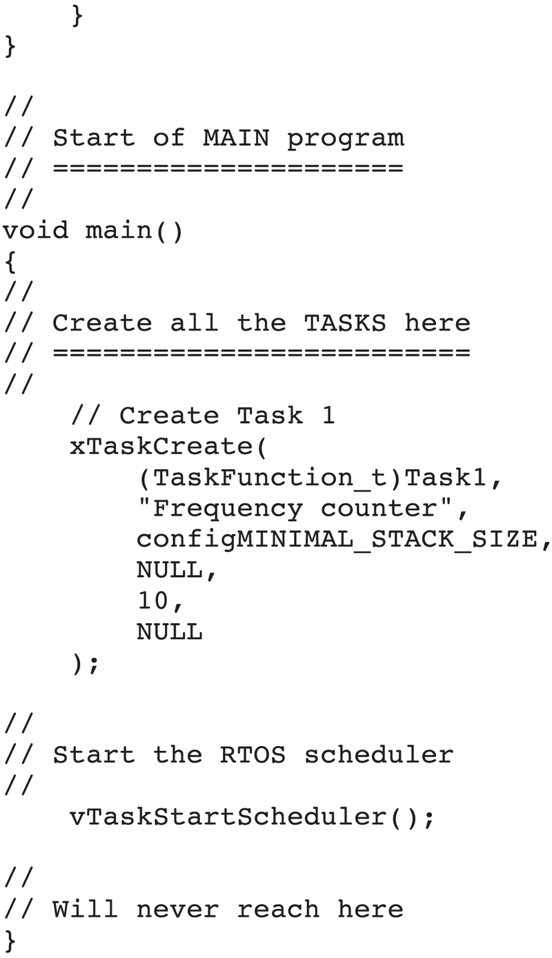
Program listing: The program listing (freqcounter.c) is shown in Fig. 13.10. There is only one task in this program in addition to the Idle task. The operation of the program is as follows:
Figure 13.10freqcounter.c program listing.
BEGIN
Configure the LCD
DO FOREVER
Wait until a rising signal edge is detected
Start timer with period of 1 second
Count the number of rising signal edges
When timer is expired display the count
ENDDO
END
The following parameters must be defined and set in file FreeRTOSConfig.h before the program can be compiled:
configUSE_TIMERS
configTIMER_TASK_PRIORITY
configTIMER_QUEUE_LENGTH
configTIMER_TASK_STACK_DEPTH
At the beginning of the program the interface between the LCD and the development board is defined, the LCD is initialized, and port pin PA2 is configured as digital input. The program then creates an auto-load timer with a period of one second (1000 ms), specifying the callback function as vFrequencyCounter. The program detects the rising edge of the input signal and increment variable count when the rising edge is detected. The code to detect the rising edge and increment count is:
while(FreqInput == 0);
count++;
while(FreqInput == 1);
The callback function is called every second when the timer expires. This function clears the LCD, converts the count into a string variable in Txt and then displays the count. The count here is the number of events happening each second, or the frequency in the case if the input is a square wave signal. Tests showed that the frequency in the upper audio range up to 30 kHz can accurately be measured and displayed on the LCD by the project. Both the task priority and the timer priority were set to 10 in this project.
13.8. Summary
In this Chapter we have learned how to use the FreeRTOS software timers in projects. In the remaining Chapters of this book we will be developing additional projects using various functions of FreeRTOS.