
Chapter 21. Describing Video Infrastructure
Upon completing this chapter, you will be able to do the following:
![]() Describe the different layers of the collaboration infrastructure
Describe the different layers of the collaboration infrastructure
![]() Describe the architectural evolution of the collaboration infrastructure
Describe the architectural evolution of the collaboration infrastructure
![]() Describe the migration from previous versions to Cisco Unified Communications 10.0
Describe the migration from previous versions to Cisco Unified Communications 10.0
![]() Describe how to use Cisco Prime Collaboration Manager for video analysis
Describe how to use Cisco Prime Collaboration Manager for video analysis
![]() Describe the high-level function of a Cisco Unified Communications Manager and Cisco TelePresence Video Communication Server implementation
Describe the high-level function of a Cisco Unified Communications Manager and Cisco TelePresence Video Communication Server implementation
![]() Describe the dual approach of integrating Cisco Unified Communications Manager and Cisco TelePresence Video Communication Server
Describe the dual approach of integrating Cisco Unified Communications Manager and Cisco TelePresence Video Communication Server
![]() Describe the characteristics of the Cisco TelePresence Video Communication Server and show when to use it
Describe the characteristics of the Cisco TelePresence Video Communication Server and show when to use it
![]() Describe the cluster limits and required resources for Cisco TelePresence Video Communications Server
Describe the cluster limits and required resources for Cisco TelePresence Video Communications Server
![]() Present the call-processing terminology for Cisco Unified Communications Manager and Cisco TelePresence Video Communication Server
Present the call-processing terminology for Cisco Unified Communications Manager and Cisco TelePresence Video Communication Server
![]() Describe how Cisco Unified Communications Manager and Cisco TelePresence Video Communication Server are connected and the information flow between these systems
Describe how Cisco Unified Communications Manager and Cisco TelePresence Video Communication Server are connected and the information flow between these systems
![]() Describe the dial plans in Cisco Unified Communications Manager and Cisco TelePresence Video Communication Server
Describe the dial plans in Cisco Unified Communications Manager and Cisco TelePresence Video Communication Server
![]() Describe conferencing in general
Describe conferencing in general
![]() Describe multiparty conference systems
Describe multiparty conference systems
![]() Describe the Cisco TelePresence Conductor functionality
Describe the Cisco TelePresence Conductor functionality
![]() Describe the Cisco Jabber Video for TelePresence client, which was formerly known as Movi
Describe the Cisco Jabber Video for TelePresence client, which was formerly known as Movi
![]() Describe the DNS SRV records for Cisco Jabber Video for TelePresence registration inside and outside the enterprise
Describe the DNS SRV records for Cisco Jabber Video for TelePresence registration inside and outside the enterprise
![]() Describe how Cisco Jabber Video for TelePresence is autoprovisioned to register with Cisco TelePresence Video Communication Server
Describe how Cisco Jabber Video for TelePresence is autoprovisioned to register with Cisco TelePresence Video Communication Server
![]() Describe the simplification of the video endpoint portfolio
Describe the simplification of the video endpoint portfolio
This chapter describes the layers of the collaboration infrastructure for video integrated solutions and explains the differences between Cisco Unified Communications Manager and Cisco TelePresence Video Communication Server (VCS) as the call-processing system. Cisco Jabber Video for TelePresence is described as a client that can be automatically provisioned and register with the Cisco TelePresence VCS only.
Cisco Collaboration Infrastructure
Figure 21-1 illustrates the different layers of the Cisco collaboration infrastructure.
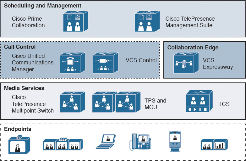
The scheduling and management layer comprises the following:
![]() Cisco Prime Collaboration: Cisco Prime Collaboration helps enable rapid installation and maintenance of Cisco Unified Communications and Cisco TelePresence components as well as the provisioning of users and services.
Cisco Prime Collaboration: Cisco Prime Collaboration helps enable rapid installation and maintenance of Cisco Unified Communications and Cisco TelePresence components as well as the provisioning of users and services.
![]() Cisco TelePresence Management Suite (Cisco TMS): Cisco TMS offers complete control and management of multiparty conferencing, infrastructure, and endpoints, to centralize management of your entire video collaboration and TelePresence network.
Cisco TelePresence Management Suite (Cisco TMS): Cisco TMS offers complete control and management of multiparty conferencing, infrastructure, and endpoints, to centralize management of your entire video collaboration and TelePresence network.
The call control and collaboration edge layer includes the following products in addition to the Cisco Unified Communications Manager (CUCM):
![]() Cisco VCS: Cisco VCS Control provides video call and session control, registrations, and enhanced security for Cisco TelePresence conferences. Cisco VCS enables features such as routing, dial plans, and bandwidth usage control, while allowing organizations to define video call-management applications that are customized to their requirements.
Cisco VCS: Cisco VCS Control provides video call and session control, registrations, and enhanced security for Cisco TelePresence conferences. Cisco VCS enables features such as routing, dial plans, and bandwidth usage control, while allowing organizations to define video call-management applications that are customized to their requirements.
![]() Cisco VCS Expressway: Cisco VCS Expressway allows video traffic to traverse the firewall securely, enabling rich video communications with partners, customers, suppliers, and mobile and teleworkers.
Cisco VCS Expressway: Cisco VCS Expressway allows video traffic to traverse the firewall securely, enabling rich video communications with partners, customers, suppliers, and mobile and teleworkers.
The media services layer consists of the following products:
![]() Cisco TelePresence Multipoint Switch: The Cisco TelePresence Multipoint Switch allows geographically dispersed organizations to hold Cisco TelePresence meetings across multiple locations reliably and easily.
Cisco TelePresence Multipoint Switch: The Cisco TelePresence Multipoint Switch allows geographically dispersed organizations to hold Cisco TelePresence meetings across multiple locations reliably and easily.
![]() Cisco TelePresence Server (Cisco TPS): Cisco TPS provides high-quality, standards-based video conferencing for users of mobile, desktop, or room systems. It works with Cisco TelePresence Conductor to offer flexible and optimized conferencing.
Cisco TelePresence Server (Cisco TPS): Cisco TPS provides high-quality, standards-based video conferencing for users of mobile, desktop, or room systems. It works with Cisco TelePresence Conductor to offer flexible and optimized conferencing.
![]() Cisco TelePresence MCU series: The Cisco TelePresence MCU series is a range of state-of-the-art multipoint control units (MCUs) that can grow with your business’s video usage over the long term.
Cisco TelePresence MCU series: The Cisco TelePresence MCU series is a range of state-of-the-art multipoint control units (MCUs) that can grow with your business’s video usage over the long term.
![]() Cisco TelePresence Content Server (TCS): Easily share knowledge using the Cisco TelePresence Content Server (TCS), which records Cisco TelePresence and third-party video conferencing meetings and multimedia presentations for live broadcast and on-demand access.
Cisco TelePresence Content Server (TCS): Easily share knowledge using the Cisco TelePresence Content Server (TCS), which records Cisco TelePresence and third-party video conferencing meetings and multimedia presentations for live broadcast and on-demand access.
The endpoint layer includes the following types of endpoints:
![]() Cisco Jabber
Cisco Jabber
![]() IP phones with video capabilities
IP phones with video capabilities
![]() Collaboration desk endpoints with video capabilities
Collaboration desk endpoints with video capabilities
![]() Collaboration room endpoints
Collaboration room endpoints
![]() Immersive TelePresence endpoints
Immersive TelePresence endpoints
Architectural Evolution
Figure 21-2 describes the components of the architectural evolution of the Cisco collaboration infrastructure.
In 2010, at the close of the TANDBERG acquisition by Cisco, the state of the collaboration infrastructure was as follows:
![]() TelePresence and Cisco Unified Communications endpoints were typically deployed on separate call-processing clusters.
TelePresence and Cisco Unified Communications endpoints were typically deployed on separate call-processing clusters.
![]() There was limited interoperability between endpoints that were bridged using the Cisco TelePresence Server.
There was limited interoperability between endpoints that were bridged using the Cisco TelePresence Server.
![]() A lot of product functional overlap existed in every category: endpoints, call control, B2B connectivity, bridging, scheduling, and management.
A lot of product functional overlap existed in every category: endpoints, call control, B2B connectivity, bridging, scheduling, and management.
![]() Different dial plans existed, including numeric and alphanumeric plans.
Different dial plans existed, including numeric and alphanumeric plans.
![]() Different methods of provisioning, management, and monitoring were used.
Different methods of provisioning, management, and monitoring were used.
![]() Features were not consistent across the portfolio.
Features were not consistent across the portfolio.
In the years 2011 to 2013, both product lines grew together:
![]() Cisco TelePresence and traditional Cisco Unified Communications (telephony and standard definition video) are merged in a converged CUCM cluster. Former TANDBERG endpoints are predominantly still registered on Cisco VCS Control.
Cisco TelePresence and traditional Cisco Unified Communications (telephony and standard definition video) are merged in a converged CUCM cluster. Former TANDBERG endpoints are predominantly still registered on Cisco VCS Control.
![]() Full native any-to-any interoperability is available between all endpoints and bridges. Ad hoc bridges are available with Cisco TelePresence Conductor on CUCM, and scheduled bridges are still registered on Cisco VCS Control.
Full native any-to-any interoperability is available between all endpoints and bridges. Ad hoc bridges are available with Cisco TelePresence Conductor on CUCM, and scheduled bridges are still registered on Cisco VCS Control.
![]() The functional overlap of products diminishes, and product roles are clarified, but consolidation is not yet fully realized.
The functional overlap of products diminishes, and product roles are clarified, but consolidation is not yet fully realized.
![]() Both numeric and alphanumeric dial plans are now fully supported across most of the portfolio.
Both numeric and alphanumeric dial plans are now fully supported across most of the portfolio.
![]() Provisioning, management, and monitoring come together and Cisco Prime Collaboration grows in functionality.
Provisioning, management, and monitoring come together and Cisco Prime Collaboration grows in functionality.
![]() Consistency of features and user experience increases across the portfolio.
Consistency of features and user experience increases across the portfolio.
![]() New, compelling solutions like Cisco WebEx Enabled TelePresence extend the video solution.
New, compelling solutions like Cisco WebEx Enabled TelePresence extend the video solution.
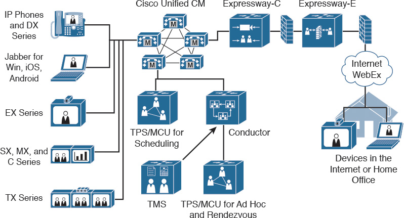
Today, these product lines are merged and offer the following benefits for the customer:
![]() All endpoints and infrastructure are merged in a converged CUCM for call control with Cisco VCS Expressway (Control and Edge) for remote and mobile access (MRA) to CUCM. This convergence enhances B2B, WebEx, and cloud-enabled TelePresence connectivity and third-party interworking.
All endpoints and infrastructure are merged in a converged CUCM for call control with Cisco VCS Expressway (Control and Edge) for remote and mobile access (MRA) to CUCM. This convergence enhances B2B, WebEx, and cloud-enabled TelePresence connectivity and third-party interworking.
![]() Multiparty bridging for audio and video for all types of conferences is now trunked through CUCM. Cisco TMS scheduled resources are still separate from Cisco TelePresence Conductor ad hoc resources.
Multiparty bridging for audio and video for all types of conferences is now trunked through CUCM. Cisco TMS scheduled resources are still separate from Cisco TelePresence Conductor ad hoc resources.
![]() Cisco Jabber is now available on Microsoft Windows, Mac OS X, iOS, and Android using Expressway. This availability provides access to CUCM and related Unified Communications services such as directories, presence, and visual voicemail without the need for a virtual private network (VPN).
Cisco Jabber is now available on Microsoft Windows, Mac OS X, iOS, and Android using Expressway. This availability provides access to CUCM and related Unified Communications services such as directories, presence, and visual voicemail without the need for a virtual private network (VPN).
![]() New applications like cloud-enabled TelePresence, video messaging, Cisco Contact Center Express remote experts, new enabling technologies like Cisco Jabber Guest and WebRTC, H.265, and scalable video coding (SVC) are available.
New applications like cloud-enabled TelePresence, video messaging, Cisco Contact Center Express remote experts, new enabling technologies like Cisco Jabber Guest and WebRTC, H.265, and scalable video coding (SVC) are available.
![]() Multiparty bridging for audio and video, for all types of conferences, is now consolidated under Cisco TelePresence Conductor with Cisco TMS for scheduling and meeting management.
Multiparty bridging for audio and video, for all types of conferences, is now consolidated under Cisco TelePresence Conductor with Cisco TMS for scheduling and meeting management.
Combined Model and Methods
This following points describe the environment of customers with an existing solution that is based on a Cisco Unified Communications version before Release 10.0 including Cisco TelePresence Video Communication Server (VCS) for video integration:
![]() Unified CM and VCS Control and Expressway
Unified CM and VCS Control and Expressway
![]() TMS and Prime Collaboration
TMS and Prime Collaboration
![]() IP phones, Jabber UC, Jabber Video (Movi), TC and TX series endpoints
IP phones, Jabber UC, Jabber Video (Movi), TC and TX series endpoints
![]() VPN-based and Expressway-based firewall traversal for RMA
VPN-based and Expressway-based firewall traversal for RMA
![]() CUBE/Expressway for B2B calling
CUBE/Expressway for B2B calling
![]() CUBE for IP public switched telephone network (PSTN) trunking
CUBE for IP public switched telephone network (PSTN) trunking
These deployments should be migrated to Version 10.x to allow optimization of the existing solution and to follow the Cisco Validated Designs for Collaboration as follows:
![]() Migrate all endpoints to Unified CM 10.x
Migrate all endpoints to Unified CM 10.x
![]() Prime Collaboration for endpoint provisioning and overall management
Prime Collaboration for endpoint provisioning and overall management
![]() TMS for scheduling and conference management
TMS for scheduling and conference management
![]() Migrate from Jabber Video (Movi) to Jabber UC 10.x
Migrate from Jabber Video (Movi) to Jabber UC 10.x
![]() Expressway X8.x for RMA and Expressway for B2B calling
Expressway X8.x for RMA and Expressway for B2B calling
![]() CUBE for IP PSTN trunking
CUBE for IP PSTN trunking
You can find additional information at http://www.cisco.com/c/en/us/solutions/enterprise/validated-designs-collaboration/index.html.
High-Level Function of Collaboration Infrastructure
Figure 21-3 describes the high-level function of a CUCM and Cisco TelePresence VCS implementation.
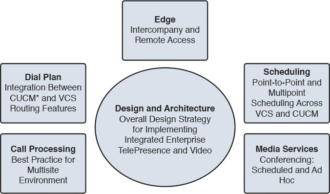
Figure 21-3 shows the main high-level functions in the collaboration infrastructure that you must consider when integrating CUCM and Cisco TelePresence VCS.
Dual Approach
Figure 21-4 describes the dual approach of integrating CUCM and Cisco TelePresence VCS.
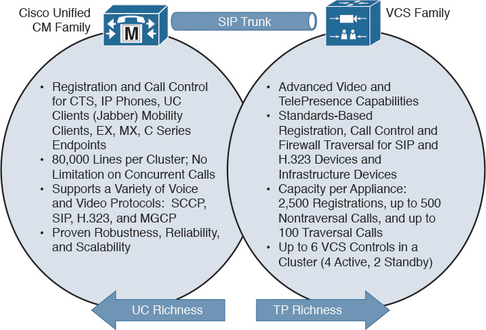
Cisco TelePresence VCS adds important telepresence enablement to a Unified Communications solution, as shown in the figure. Both systems have common areas (not shown in the figure), such as the following:
![]() Endpoint management
Endpoint management
![]() Centralized dial plans
Centralized dial plans
![]() Call detail records (CDRs)
Call detail records (CDRs)
![]() Security
Security
Cisco TelePresence VCS Characteristics
The following points show the video-related features that were ported from Cisco VCS to CUCM to merge the call-processing systems:
![]() Video encryption
Video encryption
![]() Ad hoc conferencing using Multiway Add Participant and Join features
Ad hoc conferencing using Multiway Add Participant and Join features
![]() Alphanumeric URI registration
Alphanumeric URI registration
![]() Secure firewall traversal using H.460.18 and 19
Secure firewall traversal using H.460.18 and 19
![]() TMS scheduling and management of EX, SX, MX, DX and C series endpoints on CUCM
TMS scheduling and management of EX, SX, MX, DX and C series endpoints on CUCM
The following features are exclusive to Cisco VCS and include the registration of H.323 devices, SIP-H.323 interworking, and the Cisco Jabber Video for TelePresence (Movi) client registration:
![]() H.323 registration
H.323 registration
![]() SIP-H.323 interworking
SIP-H.323 interworking
![]() Cisco Jabber Video (Movi) support
Cisco Jabber Video (Movi) support
However, the migration path for Movi is to use Cisco Jabber integrated with CUCM in phone mode or with CUCM IM and Presence in softphone or deskphone mode.
The recommendation for greenfield deployments is to plan for CUCM and not for the Cisco VCS deployment. For Cisco VCS customers, you should find a way to migrate to CUCM because, for example, the new Cisco DX series video phones do not work with Cisco VCS.
Cisco VCS Cluster Size
The following points are the cluster performance limits for Cisco VCS:
![]() 10,000 active users and redundancy for 5000 users
10,000 active users and redundancy for 5000 users
![]() Call limits per cluster are 400 traversal and 2000 nontraversal video calls
Call limits per cluster are 400 traversal and 2000 nontraversal video calls
![]() OVA virtual resources for one large Cisco VCS server:
OVA virtual resources for one large Cisco VCS server:
![]() 8 vCPUs with a core speed of 3.2 GHz, 8-GB vRAM, 132-GB vDisk
8 vCPUs with a core speed of 3.2 GHz, 8-GB vRAM, 132-GB vDisk
![]() 3 vNICs, each 10 Gbps
3 vNICs, each 10 Gbps
This performance data and the associated limits are based on 100 simultaneous interworked and encrypted calls at 768 kbps:
![]() The number of provisioned users on a single Cisco VCS cluster is 10,000.
The number of provisioned users on a single Cisco VCS cluster is 10,000.
![]() Cisco TMS can support 100,000 provisioned users.
Cisco TMS can support 100,000 provisioned users.
![]() Users should be partitioned into groups to control how provisioning is sent to VCS clusters.
Users should be partitioned into groups to control how provisioning is sent to VCS clusters.
Interactive Connectivity Establishment (ICE) is a technique used in computer networking involving network address translators (NATs) in Internet applications of Voice over Internet Protocol (VoIP), peer-to-peer communications, video, instant messaging and other interactive media. Call signaling for nontraversal calls is performed only by Cisco VCS:
![]() In a call between Session Initiation Protocol (SIP) user agents (UAs), both SIP UAs have the same SIP contact address and source IP address.
In a call between Session Initiation Protocol (SIP) user agents (UAs), both SIP UAs have the same SIP contact address and source IP address.
![]() SIP calls are managed as ICE calls.
SIP calls are managed as ICE calls.
Call signaling and media routing for traversal calls are performed by Cisco VCS:
![]() Traversal calls are managed between instances of Cisco VCS Expressway (VCS-E).
Traversal calls are managed between instances of Cisco VCS Expressway (VCS-E).
![]() Cisco VCS manages IPv4-IPv6 interworking calls.
Cisco VCS manages IPv4-IPv6 interworking calls.
![]() Cisco VCS manages SIP-H.323 interworking calls.
Cisco VCS manages SIP-H.323 interworking calls.
![]() Back-to-back user agent (B2BUA) calls; for example, Microsoft Skype for Business integration.
Back-to-back user agent (B2BUA) calls; for example, Microsoft Skype for Business integration.
![]() In a call between SIP UAs, one or both of the SIP UAs can have a SIP contact address that is different from the source IP address.
In a call between SIP UAs, one or both of the SIP UAs can have a SIP contact address that is different from the source IP address.
![]() Calls between an H.323 endpoint registered on Cisco VCS-E with H.460 traversal capability.
Calls between an H.323 endpoint registered on Cisco VCS-E with H.460 traversal capability.
Call Control Terminology
Table 21-1 presents the comparison of call-processing terminology for CUCM and Cisco TelePresence VCS.
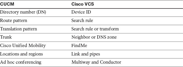
This table helps you distinguish between the terms that are used in the different call-processing systems.
Connecting CUCM and VCS Clusters
Figure 21-5 illustrates how CUCM and Cisco TelePresence VCS are connected and the information flow between these systems.
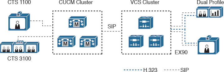
With CUCM 10.x, the name or IP address of a server is replaced by the organization top-level domain (OTLD) in outgoing messages (for example, cisco.com). This change allows you to call [email protected] instead of dialing [email protected]. The enhanced security support for 80-bit authentication tags was implemented for military customers to secure video communications.
In connecting CUCM with a cluster of Cisco VCS peers, there are two methods of providing Unified CM with the addresses of the VCS cluster peers:
![]() The trunk to the Cisco VCS specifies the DNS SRV address for the VCS cluster. Each peer should be set with an equal priority and weight in SRV records on the DNS server.
The trunk to the Cisco VCS specifies the DNS SRV address for the VCS cluster. Each peer should be set with an equal priority and weight in SRV records on the DNS server.
![]() The trunk to the Cisco VCS specifies a list of VCS peers as IP addresses. You can also set up multiple SIP trunks to each peer in the VCS cluster. This option is preferred when using flat dial plans.
The trunk to the Cisco VCS specifies a list of VCS peers as IP addresses. You can also set up multiple SIP trunks to each peer in the VCS cluster. This option is preferred when using flat dial plans.
When connecting VCS to a cluster of Unified CM nodes, VCS must be able to route calls to each Unified CM node. This routing can be done in the following two ways (in order of preference):
![]() Route calls using a single neighbor zone in VCS with the Unified CM nodes listed as location peer addresses.
Route calls using a single neighbor zone in VCS with the Unified CM nodes listed as location peer addresses.
![]() Route calls using DNS SRV records and a VCS DNS zone.
Route calls using DNS SRV records and a VCS DNS zone.
Note that both options ensure that the Cisco VCS-to-Unified CM call load is shared across Unified CM nodes.
Dial Plans
Table 21-2 compares the dial plans in CUCM and Cisco TelePresence VCS.
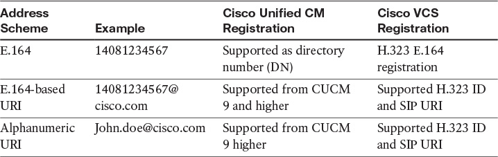
In CUCM, the E.164 or +E.164 numbers are used for call routing. URI dialing is used in the Cisco VCS. Both dial plans are relevant:
![]() E.164 addresses allow easy integration with the PSTN and audio-only endpoints.
E.164 addresses allow easy integration with the PSTN and audio-only endpoints.
![]() URI addresses allow easier back-to-back communications using domain names and are generally more intuitive for end users.
URI addresses allow easier back-to-back communications using domain names and are generally more intuitive for end users.
CUCM and Cisco VCS do not share a database, so default routes are required between these systems. As an example, you dial [email protected] on CUCM but cannot find the user on CUCM. The call is sent to Cisco VCS via the default route. There are two possibilities now. First, you find a match for [email protected], and you extend the call to the user phone. The second option is that Cisco VCS does not find a match and routes the call back. These systems will prevent looping after a certain number of hops.
In the past, E.164 was usually used in voice networks and H.323 and URI were used within SIP networks. In the future, collaboration services, instant messaging (IM), voice, video, and social communication will converge more and more. The endpoints and the infrastructure will need to support both address schemes to support scalable and consistent dialing.
Conferencing
Conferencing occurs when more than two participants join a meeting with a voice or video device. The challenge is to have a consistent user experience in voice or video conferences and to select the correct conference resource depending on the device, especially when mixing standard definition and high-definition video devices.
The Cisco focus for the future is Cisco ActivePresence using Cisco TelePresence Server instead of multipoint control units (MCUs) with lots of different layouts.
Ad hoc conferences are impromptu meetings; they are not scheduled beforehand and do not require an administrator to initiate them. Ad hoc conferences are suitable for smaller, on-the-fly meetings. A point-to-point call that is escalated to a multipoint call is considered an ad hoc conference.
Rendezvous conferences are also called Meet-Me, permanent, or static conferences. These conferences require that endpoints dial into a predetermined number and are often used for recurring group meetings that involve different endpoints each time.
Scheduled conferences provide a guarantee that endpoints and multipoint resources will be available at a certain time. Endpoints join manually or are automatically connected by the multipoint resource.
The Cisco TelePresence MCU 5300 series, for example, offers more than 50 layouts for continuous presence. All ports on this MCU also support advanced continuous presence.
The future trend is active presence supported by Cisco TelePresence Server. Cisco ActivePresence capability supports a full-screen immersive view of the primary speaker with an overlay of others who are participating in the call. ActivePresence is designed to maximize the large-scale immersive experience and is available on all ports of the Cisco TelePresence Server. The server interworks with Polycom RPX and TPX telepresence systems while preserving the full Cisco ActivePresence view. Four layout families are provided for single-screen endpoints, including panel-switched Cisco ActivePresence capability.
Up to 9 ActivePresence windows are supported on a single screen at one time. In a triple-screen system, a total of 27 ActivePresence windows are supported.
Multiparty Conferencing
Figure 21-6 illustrates some options of TPS.
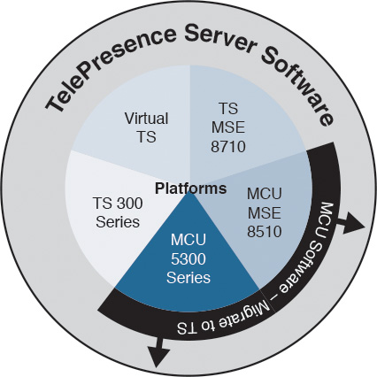
With universal encoding, you can optimize the quality for users with different video qualities (for example, in a mixed video conference with participants using 360p, 720p, and 1080p resolution). In addition, the bandwidth is adapted between users with limited and slow Internet lines such as a 1-Mbps connection and users having 100 Mbps and more. Every single connection is transcoded to its best possible quality, forming a multiparty solution.
The following are guidelines for Cisco multiparty conferencing:
![]() Cisco TelePresence Server and Cisco TelePresence Conductor form a multiparty solution:
Cisco TelePresence Server and Cisco TelePresence Conductor form a multiparty solution:
![]() Any-to-any device connectivity, from mobile to immersive, bringing together video, web, and voice conferencing
Any-to-any device connectivity, from mobile to immersive, bringing together video, web, and voice conferencing
![]() Platforms to suit all deployment scenarios with a common application and industry-leading user experience
Platforms to suit all deployment scenarios with a common application and industry-leading user experience
![]() MCU hardware platforms can run Cisco TelePresence Server software.
MCU hardware platforms can run Cisco TelePresence Server software.
![]() Customers migrate when appropriate
Customers migrate when appropriate
Cisco TelePresence Conductor
The following points summarize the Cisco TelePresence Conductor functionality:
![]() Improved user experience
Improved user experience
![]() Simple to use
Simple to use
![]() Zero downtime
Zero downtime
![]() Extended scale
Extended scale
![]() Enhanced conference size
Enhanced conference size
![]() Intelligent resource usage
Intelligent resource usage
![]() Any-to-any collaboration
Any-to-any collaboration
![]() Interoperable
Interoperable
![]() Standards based
Standards based
Instead of managing the MCUs directly with Cisco TelePresence VCS or CUCM, the MCUs are managed by Cisco TelePresence Conductor. There are two reasons for virtualizing and centralizing MCU management:
![]() You can have multiple MCUs, cascade them geographically, and define backup conference resources.
You can have multiple MCUs, cascade them geographically, and define backup conference resources.
![]() Because pervasive video is complex and the call can happen anywhere in the organization, this approach allows optimal resources to be found depending on the device location.
Because pervasive video is complex and the call can happen anywhere in the organization, this approach allows optimal resources to be found depending on the device location.
For example, assume that there are three locations, one each in Asia, Europe, and America. When the Europe conference bridge is fully utilized, users should not get a failure message saying that there are no video resources available, or fall back to audio only. Cisco TelePresence Conductor manages this situation by automatically choosing an underutilized conference bridge, but always using local resources first, based on the location configuration. With preferences set, an overflow situation selects the next best conference bridge. Cisco TelePresence Conductor is best described as a centralized MCU controller.
Cisco TelePresence Conductor is mandatory for the new pervasive conferencing platforms such as Cisco TelePresence Server on a VM and TelePresence Server on the Cisco Multiparty Media 310/320.
Cisco Jabber Video for TelePresence (Movi)
Figure 21-7 illustrates the Cisco Jabber Video for TelePresence client, which was formerly known as Movi.
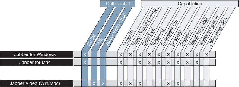
The presence functionality is limited to the Cisco TelePresence VCS cluster and only to video endpoints.
Cisco Jabber requires CUCM and Cisco Unified Communications IM and Presence to register and is a rich media-enabled client.
Cisco Jabber Video for TelePresence is a video-centric client that can only be registered with Cisco TelePresence VCS and can reach other clients on CUCM via a SIP trunk. There is also a cloud-based solution, where you can register the Cisco Jabber Video for TelePresence client as well. Cisco Jabber Video for TelePresence uses the Cisco Precision Video Engine technology, which is also used by the Cisco TelePresence EX60 and EX90 systems.
The software requirements to deploy Cisco Jabber Video for TelePresence are as follows:
![]() Cisco TelePresence VCS
Cisco TelePresence VCS
![]() Cisco TMS
Cisco TMS
The provisioning option must be enabled on both products.
Cisco recommends using the Cisco TelePresence PrecisionHD USB Camera for Cisco Jabber Video for TelePresence on your PC for the best video and audio user experience.
To register, the client needs to locate the provisioning service and register with Cisco TelePresence VCS. You must set up the following to successfully register Cisco Jabber Video for TelePresence:
![]() SIP domain on the Cisco VCS with which the client will register
SIP domain on the Cisco VCS with which the client will register
![]() DNS address of the primary VCS control cluster
DNS address of the primary VCS control cluster
![]() (Optional) DNS address of a Cisco VCS Expressway cluster
(Optional) DNS address of a Cisco VCS Expressway cluster
These settings can be preset by the administrator so that users do not have to set these parameters. In fact, if these settings are configured, users cannot change them.
DNS SRV Records
The following points summarize the DNS protocol:
![]() DNS service records, defined in RFC 2782, are a method to define a DNS record for a service instead of a specific host.
DNS service records, defined in RFC 2782, are a method to define a DNS record for a service instead of a specific host.
![]() The DNS SRV record resolves to one or more hostnames of servers and port numbers where the desired service may be found.
The DNS SRV record resolves to one or more hostnames of servers and port numbers where the desired service may be found.
![]() It can be used to implement location-specific registration behavior.
It can be used to implement location-specific registration behavior.
For registration within the enterprise, set up the DNS SRV records for the client to register with the Cisco TelePresence VCS cluster, where the devices use round-robin registration according to the DNS settings shown as follows:
_service._protocol.domain TTL class SRV priority weight port target
_sip._tcp.clustername.internal.com 86400 IN SRV 10 60 5060 server1.cisco.com.
_sip._tcp.clustername.internal.com 86400 IN SRV 10 60 5060 server2.cisco.com.
_sip._tcp.clustername.internal.com 86400 IN SRV 10 60 5060 server3.cisco.com.
_sip._tcp.clustername.internal.com 86400 IN SRV 10 60 5061 server1.cisco.com.
_sip._tcp.clustername.internal.com 86400 IN SRV 10 60 5061 server2.cisco.com.
_sip._tcp.clustername.internal.com 86400 IN SRV 10 60 5061 server3.cisco.com.
For external access, Cisco Jabber Video for TelePresence connects to the Cisco TelePresence VCS Expressway using firewall traversal:
_service._protocol.domain TTL class SRV priority weight port target
_sip._tcp.express.external.com 86400 IN SRV 10 60 5060 server1.external.com.
_sip._tcp.express.external.com 86400 IN SRV 10 60 5060 server2.external.com.
Automated Provisioning with Cisco VCS and TMS
Figure 21-8 shows how Cisco Jabber Video for TelePresence autoregisters. Note that users can also be configured manually.
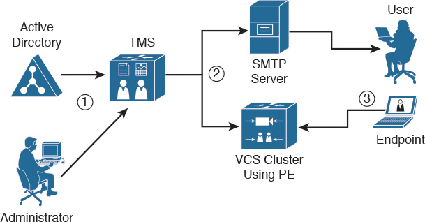
In addition to Step 3, where the client successfully registers with Cisco VCS, the following happens:
![]() The endpoint registers to a Cisco VCS per the provisioning profile and the endpoint is ready for SIP calls.
The endpoint registers to a Cisco VCS per the provisioning profile and the endpoint is ready for SIP calls.
![]() The endpoint subscribes to Cisco VCS for directory services.
The endpoint subscribes to Cisco VCS for directory services.
Provisioning Extension characteristics are as follows:
![]() Provisioning of Cisco Jabber Video endpoints has evolved from provisioning agent to provisioning extension.
Provisioning of Cisco Jabber Video endpoints has evolved from provisioning agent to provisioning extension.
![]() Provisioning Extension is the only method for newer endpoints such as the EX series, C series, and Cisco Jabber Video starting in Cisco TMS Release 14.1 and later.
Provisioning Extension is the only method for newer endpoints such as the EX series, C series, and Cisco Jabber Video starting in Cisco TMS Release 14.1 and later.
![]() Provisioning Extension is a feature activated on the Cisco TMS server and stores endpoint configuration data in an SQL database.
Provisioning Extension is a feature activated on the Cisco TMS server and stores endpoint configuration data in an SQL database.
![]() Endpoints send SIP subscribe messages to the VCS, which retrieves the data from the Cisco TMS Provisioning Extension database and provides those settings to the endpoint.
Endpoints send SIP subscribe messages to the VCS, which retrieves the data from the Cisco TMS Provisioning Extension database and provides those settings to the endpoint.
Portfolio Simplification
Figure 21-9 describes the simplification of the video endpoint portfolio.
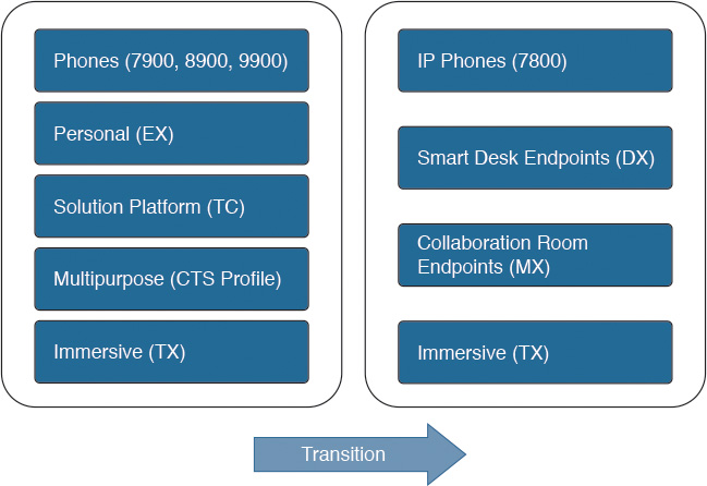
Because customers had difficulties in distinguishing among all the different video endpoints, Cisco simplified the video endpoint portfolio. Figure 21-9 shows the new video endpoint groupings. For more detail on collaboration endpoints, go to http://www.cisco.com/c/en/us/products/collaboration-endpoints/index.html.
Summary
This section summarizes the key points that were discussed in this chapter:
![]() CUCM is the main call control system to register all video endpoints. Cisco Jabber Video is the only exception and requires Cisco VCS to register.
CUCM is the main call control system to register all video endpoints. Cisco Jabber Video is the only exception and requires Cisco VCS to register.
![]() Cisco TMS is used for scheduled conferences. Cisco TMS can also be used to provision Cisco Jabber for video.
Cisco TMS is used for scheduled conferences. Cisco TMS can also be used to provision Cisco Jabber for video.
![]() MCU resource utilization can be optimized with Cisco TelePresence Conductor, especially when users have different resolutions and devices.
MCU resource utilization can be optimized with Cisco TelePresence Conductor, especially when users have different resolutions and devices.
This chapter described the Cisco Jabber Video client and its registration with Cisco VCS. The CUCM and Cisco VCS call-processing systems were compared, and Cisco TMS was described as a scheduling and provisioning tool for Cisco Jabber Video.
Review Questions
Answer the following questions, and then see Appendix A, “Answers to Review Questions,” for the answers.
1. How many active Cisco TelePresence Video Communication Servers can you have in a VCS cluster?
a. 1
b. 2
c. 4
d. 5
e. 6
2. How many vNICs are required on a Cisco TelePresence Video Communication Server?
a. 1
b. 2
c. 3
d. 4
3. What Cisco TelePresence Video Communication Server terminology matches the route pattern in CUCM?
a. Neighbor
b. Search rule
c. Transform
d. None of the above
4. Cisco TelePresence Server on Virtual Machine and TelePresence Server on Multiparty Media 310/320 can be deployed without Cisco TelePresence Conductor.
a. True
b. False