
Alternating Current Generators
Airgap flux and open-circuit e.m.f. 28.2
Open-circuit e.m.f.: integral slots per pole 28.2.2
Alternating current windings 28.3
Cylindrical-rotor machine 28.7.1
Salient-pole rotor machine 28.7.2
Magnitudes and equivalence of stator and rotor m.m.f. 28.7.3
Reactances and time constants 28.8
Armature leakage reactance 28.8.1
Magnetisation (armature reaction) reactances 28.8.2
Transient and subtransient reactances 28.8.4
Negative-sequence reactance 28.8.5
Zero-sequence reactance 28.8.6
On-load excitation 28.12 28/31
M.m.f. phasor diagram 28.12.1 28/31
The ANSI Potier reactance method 28.12.2 28/31
Use of design calculation 28.12.3 28/32
Sudden three-phase short circuit 28.13 28/32
D.c. exciters 28.14.1 28/36
A.c. exciters with static rectifiers 28.14.2 28/36
Brushless excitation 28.14.3 28/36
Thyristor excitation 28.14.4 28/37
Excitation systems circuits 28.14.5 28/37
Excitation control 28.14.6 28/37
Basic principles of voltage control 28.14.7 28/38
Additional control features 28.14.8 28/40
Overall voltage response 28.14.9 28/40
Digital control 28.14.10 28/41
Turbogenerators 28.15 28/41
Main dimensions 28.15.1 28/41
Rotor body 28.15.2 28/42
Rotor winding 28.15.3 28/42
Stator core 28.15.4 28/43
Stator casing 28.15.5 28/43
Stator winding 28.15.6 28/43
Cooling 28.15.7 28/43
Generator—transformer connection 28.16 28/46
Hydrogenerators 28.17 28/46
Introduction 28.17.1 28/46
Construction 28.17.2 28/47
Cooling 28.17.3 28/49
Excitation 28.17.4 28/49
Pumped storage units 28.17.5 28/49
Salient-pole generators other than hydrogenerators 28.18 28/50
Application 28.18.1 28/50
Construction 28.18.2 28/51
Ventilation and cooling 28.18.3 28/51
Particular design requirements 28.18.4 28/52
Synchronous compensators 28.19 28/52
Induction generators 28.20 28/53
Standards 28.21 28/53
28.1 Introduction
For the generation, transmission, distribution and use of electrical power the three-phase system has large economic and practical advantages over single-phase or two-phase systems. Hence the great majority of alternating-current (a.c.) generators are three-phase machines, operating at one of the standard frequencies, 50 or 60 Hz. Some generators operate at other frequencies; examples are: (a) generators up to several megawatts in output operating at 162/3 Hz have been used for years to supply rail traction systems, mostly in Europe, (b) high frequency generators, at 500–10000 Hz, were used extensively for induction heating in industrial processes, (c) small shaft mounted generators with more than three phases are used as exciters for synchronous generators and some hydrogenerators, (d) aircraft ground power supplies operating at 400 Hz, and (e) a growing trend for machines to operate at other variable frequencies with power electronics being used to convert their output to 50 or 60 Hz. However, due to the cost of the electronic conditioning equipment, these are largely limited to less than 150 kW in output and under 1000 V.
The form of construction of the generator depends on its output power and its speed: these are determined by the prime mover that drives it. To generate at a frequency of f hertz when driven at n rev/min the generator must have 2p poles, where
n is the synchronous speed, being the same as the speed of rotation of the magnetic field produced by currents in a three-phase winding when connected to a supply of frequency f Hz. The maximum permissible diameter of the rotor will be determined by the rotational stresses acting on it and thus the speed of rotation determines the shape of the generator. For a given output power, a high-speed machine will have a smaller diameter, and longer length than a low-speed machine.
Generators may be classified as follows.
Synchronous generator: This type of generator requires a winding carrying direct current (or in small sizes a series of permanent magnets) to establish the magnetic flux. In nearly all machines this excitation winding (known as the field winding) is carried on the rotor, which for a 50 or 60 Hz output must rotate at the synchronous speed.
There are two sorts of synchronous generator which are differentiated by the type of rotor used; rotors are either cylindrical or of the salient pole type.
The first type of synchronous generators are known as turbogenerators. This family of machines use a cylindrical rotor in which the field winding is housed in axial slots. They are invariably driven by a steam turbine or a gas turbine. At ratings below 60 MW a gear box may be used to provide a rotational speed of 3600 (2 pole) or 1800 rev/min (4 pole) to provide power at 60 Hz, or 3000 rev/min (2 pole) or 1500 rev/min (4 pole) to provide power at 50 Hz. Alternatively, and especially at higher power ratings the generator is directly driven by the steam or gas turbine. The rotors will thus have either two or four poles. Smaller machines may use a laminated construction for the rotor while larger machines will use a forged rotor. A feature of these machines is that their length is several times their diameter. Power outputs range from a few megawatts up to about 1500 MW. The machine is cooled by circulating air or hydrogen over the active parts or water through the windings. Hydrogen was commonly used for outputs greater than about 50 MW; water was, and still is, used for the stator winding with outputs exceeding about 200 MW. Air-cooled machines are now available up to almost 200 MW.
The second type of synchronous generators use a salient pole rotor. Types of salient pole machines are:
Hydrogenerators: This is a family of salient pole machines driven by water turbines at a speed in the range 50–1000 rev/min. The speed depends on the type of turbine, which in turn depends on the head and the flow rate of the water available. At low speeds, the permissible rotor diameter will be several times its active length. Generally, the largest allowable diameter of rotor is used to maximise the machine’s inertia which is an important part of governing the water turbine. Outputs up to 800 MW have been achieved. A small high-speed unit will have a horizontal shaft, but for reasons of mechanical construction and stability larger machines have vertical shafts.
Reciprocating gas, diesel or petrol engine-driven generators: For this application, the generator may be coupled directly to the internal combustion engine and the generator will invariably be of the salient pole construction. Many combinations of output power and speed are available, from a few kilovoltamperes, usually at four-pole speed, up to 45 MW or more at 100 rev/min, using a 2 stroke diesel engine of the type used for ship propulsion.
Steam turbine or gas turbine driven generators: Salient pole generators connected to these prime movers are driven through a gearbox, usually at 4-pole speed. Ratings are limited to below 60 MW both by the gearbox capacity and by the difficulty of holding large salient pole rotors together.
Synchronous compensators (also known as synchronous capacitors): These machines draw current from the system at zero power factor, lagging or leading as required to control the voltage of the system. They also draw a small amount of real power to maintain the synchronous rotation. They will usually have six or eight salient poles, and a rating in the range from a few megavolt-amperes up to say 350 MVAR. For machines larger than say 50 MVAR, hydrogen cooling is used to reduce the windage loss. The synchronous compensator has been rendered obsolete by the development of static volt-ampere (VAR) control equipment.
Asynchronous (induction) generators: In construction these machines resemble induction motors, and similarly draw their magnetising current from the power system, to which they deliver power when driven at very slightly above synchronous speed. Ratings are usually less than 3 MW, at speeds up to 1000 rev/min. Much smaller units, operating with capacitor excitation circuits, can provide isolated power supplies.
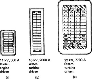
For generators of all types the practicable and economic voltage increases with the increase of rated output in order to limit the amount of current to be handled to a manageable level. Some standards specify preferred voltages, and some are normally mandatory. Typical ranges of output and voltage are:
![]()
However, a number of manufacturers have found significant markets by going away from these norms. Low voltage, high current machines together with an appropriate transformer have found favour where regulations restrict the installation of higher voltage generators. Conversely, high voltage generators, even at very modest outputs have proved attractive as the cost of a step-up transformer can be avoided.
Operating generators singly or in a group: When a generating set runs alone to supply power to a load, the prime mover supplies the active power demanded. As the demand changes, small changes of speed cause the governor to adjust the mechanical input power to maintain as nearly as possible the correct speed and frequency. The generator supplies the active power and the reactive power required by the load, and this determines the power factor. Changing the generator’s field current changes the terminal voltage, and the consequent changes in active and reactive power depend on the nature of the load, e.g. the proportion of motor load to static load. Usually, as the load changes, the voltage is held almost constant by adjustments to the excitation made by the automatic voltage regulator.
Most generators, however, are synchronous machines connected to an extensive supply network, and changing the excitation of one machine does not affect the system voltage, the speed or the power output of the generator. It changes only the reactive power, and a compensating change in reactive power is shared by other generators on the same or neighbouring bus-bars. Thus adjusting the generator field current when it is connected to a system results only in a change in the power factor at which the generator operates.
System engineers find it convenient to regard active power in watts (P) and reactive power in vars (Q) (the two components of the apparent power in volt-amperes (VA)) as separate but related entities to be generated, transmitted and absorbed.
Induction motors, chokes, transformers and underexcited synchronous machines all draw magnetising current, lagging the supply voltage by 90°. By convention, this is regarded as a demand for positive vars from the system. Capacitors and overexcited synchronous machines draw leading current, and so supply positive vars to the system. A synchronous machine is overexcited if its field current is more than is needed to make it operate at unity power factor.
28.2 Airgap flux and open-circuit e.m.f.1, 6, 7, 8, 11, 17, 19, 23
28.2.1 Airgap flux waveforms7,16,23,44–47
Figure 28.1 shows the flux pattern of a turbogenerator (t.g.) on open circuit, and flux waveforms for it and for an 18-pole salient-pole (s.p.) generator. The t.g. flux waveform is inherently trapezoidal because of the distributed field winding and uniform length of airgap. Prominent ripples caused by the stator slots and teeth have been omitted (see Section 28.2.4).
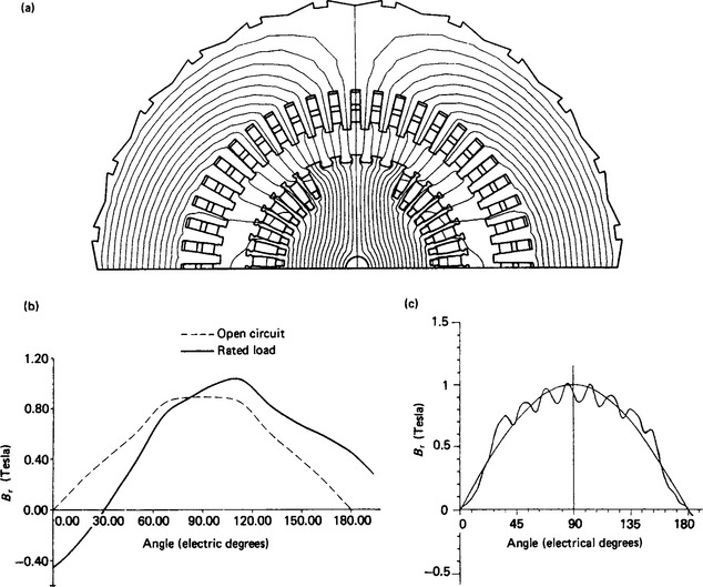
Figure 28.1 (a) Flux distribution of a turbogenerator on open circuit; (b) Flux waveforms of a turbogenerator; (c) Flux waveform of a salient pole generator on open circuit
The salient pole generator flux waveform is inherently rectangular, with short sections of low density between the poles. In this example, however, the shape is closer to sinusoidal, as the fundamental component shows, because the machine was designed with shaped pole shoes. These ensure that the length of the airgap at the extremities of the pole shoe is greater than on the pole centre line. The slot ripples which arise as a result of the stator slot opening have been retained: they are not quite symmetrical because the stator did not have a whole number of slots per pole (actually 10 1/2). Where integral slots per pole are used, great care is needed in the design and spacing of the pole face damper damper bars in order to avoid further additional ripples appearing in the voltage waveform.
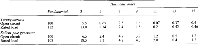
These waveforms were produced using finite element analysis: the harmonic contents of the flux waves are shown in Table 28.1. The reference value of 100% is the peak of the fundamental component of the open-circuit wave of each machine.
Even harmonics do not normally occur on open circuit, because the waveshape is the same under all the poles, and is symmetrical about each pole centre line. All the harmonic flux density curves go through zero at the interpolar axes. The total flux per pole is, therefore, the fundamental component plus or minus the flux of one pole-pitch of each harmonic: ‘plus’ if the harmonic has a negative peak at the positive peak of the fundamental, and vice versa.
Wieseman44 gave curves for a salient pole machine relating the peak flux densities of the fundamental and of the third harmonic to the peak of the actual flux wave. The multipliers
were deduced as functions of the pole arc to pole pitch ratio, the minimum airgap to pole pitch ratio and maximum edge airgap to minimum airgap.
Ginsberg et al.45 gave curves from which the flux wave fundamental and harmonics up to the 11th can be estimated, again in terms of the airgap lengths and pole profile.
With usual pole shoe profiles, C1 is between 1.0 and 1.1, i.e. the actual flux wave is a bit flatter than a sine wave, and the total flux per pole is rather more than the fundamental flux Φ, alone. Wieseman’s factor kΦ is the total flux divided by the fundamental component. Narrow poles with an edge airgap of about twice the minimum tend to give a peaky waveform with Cl just less than 1.0 and kΦ down to about 0.93. Wider poles and a uniform airgap give kΦ up to 1.06. The third harmonic flux can be made small by using a pole arc: pole pitch ratio close to 2/3; this together with a ratio maximum: minimum airgap ratio of 1.5 gives a kΦ value close to unity. If Φ is calculated from the e.m.f. equation, total flux and harmonic fluxes can be calculated.
Ginsberg et al.46,47 provide curves from which the harmonic e.m.f.s on load could be calculated, as a per unit value of the fundamental. For detailed analysis, harmonic fluxes now are calculated by computer, e.g. by finite-element solution of the magnetic-field equations.
28.2.2 Open-circuit e.m.f.: integral slots per pole
28.2.2.1 Fundamental frequency e.m.f
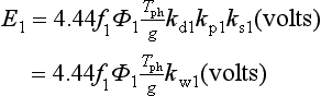
The e.m.f. induced in a single conductor lying parallel to the shaft axis has the same waveform as the flux wave. It contains all the space harmonics in the same proportions as in the flux density. It may also contain ripples caused by local variations in density caused by the winding slots (see Section 28.2.4). The root-mean-square (r.m.s.) value of the fundamental frequency component of the e.m.f. in a coil of one turn, spanning exactly one fundamental pole pitch, is
where Φ1 is the fundamental flux per pole (in webers) and f is the frequency (in hertz).
28.2.2.2 Pitch factor, kp1
If there are Np slots per pole, and the coil spans S teeth, it is short-pitched by an electrical angle
and the e.m.f.s generated in each of the two coil sides will be out of phase with respect to each other by β degrees.
The total e.m.f. is, therefore that of a full-pitch coil reduced by the factor
28.2.2.3 Distribution factor kd1
If there are q slots per pole per phase (q = Np/3 for a three-phase machine), where q is an integer, the phase difference between successive slots causes the sum of their e.m.f.sto be less than q times the e.m.f. per slot by the distribution factor, or spread factor kd1. This is because vectorally each successive coil voltage is at an angle to its predecessor. This angle is determined by the total number of stator slots distributed around the bore of the stator.
where α is the electrical angle between adjacent slots. α is numerically equal to 180°/Np electrical degrees or 60°/q for three phases, with the usual 60° coil phase spread. Then, for a three-phase winding,
28.2.2.4 Skew factor, ksl
If the winding slot, or the longitudinal axis of the pole, is skewed at an angle δ to the shaft axis, there is a progressive change in phase of the e.m.f. along each conductor. The conductor e.m.f., and hence the phase e.m.f., is reduced by the skew factor
Then, for a phase comprising of Tph turns, divided into g parallel circuits, the fundamental frequency e.m.f. is
28.2.2.5 Harmonic e.m.f.s
For the following reasons a lot of attention is now being paid to the harmonic content of the generator’s voltage waveform especially with the advent of increasing amounts of private power generation equipment connected to networks.
(1) Limits of telephone interference factor (t.h.f.) are specified in many standards, and the weighting factors emphasise harmonics that can be caused by slot ripples if the design does not suppress them.
(2) Legislation is impending in the form of the Electromagnetic Compatibility Directive (EMC) 89/336/EEC. This will specify limits for the maximum levels of emitted electromagnetic radiation, and of the levels of voltage or current that can be impressed on the power system or on the load connected to the generator.
(3) Generators are being more frequently required to provide a backup supply to uninterruptible power supplies if the mains supply fails. These schemes are used to feed loads that are sensitive to voltage distortion, such as computers, television monitors and control systems.
(4) There is increased concern that harmonic currents may be large enough to cause unacceptable extra heating and losses, both in the generator and in equipment supplied by it.
(5) Inadvertent malfunction of protection and switching equipment can occur particulaly if the equipment is set to trigger at the zero crossing point of the voltage waveform.
It is difficult to estimate how large the harmonic currents arising from the harmonic voltages will be. Their values depend on the impedances of the system and of the generator at the harmonic frequency, and on the nature of the connection between their neutral points.42
The lower-frequency harmonics, up to say the 13th order, are produced by harmonics in the main flux wave. These result from the non-sinusoidal distribution of magnetomotive force (m.m.f.) and the non-uniform radial permeance around the circumference of the airgap. Hence they are often called rotor permeance harmonic e.m.f.s. The magnitude of each compared with the fundamental e.m.f. depends on the harmonic flux density relative to the fundamental density, and on the harmonic wavelength relative to the spacing and span of the stator coils, i.e. on the winding factors kd, kp and ks at the relevant frequency.
E.m.f.s at frequencies associated with the number of stator slots are caused by: (a) variations in gap permeance as the poles pass the stator slots and teeth; and (b) flux waves produced by currents induced at slot frequency in the damper winding, field winding and solid steel of the rotor. These e.m.f.s are generally called slot ripple e.m.f.s (see Section 28.2.4).
Considering only the field form harmonics, and taking q as an integer, the pole span of the n th harmonic flux is 1/n of the fundamental span, and the harmonic flux per pole
where B1, and Bn are the peak or average flux densities.
The harmonic e.m.f. generated as a result of this flux is
Because any angle α on the fundamental scale embraces na of the n th harmonic, the winding factors become (where q is an integer)
The r.m.s. value of the total e.m.f. per phase is then
The lower harmonic e.m.f.s are usually a few per cent of En and the higher orders smaller still. The total e.m.f. Eph is rarely significantly greater than the fundamental, E1 although the harmonic e.m.f.s themselves may be troublesome.
For q = 1, kd1 is 0.966, decreasing steadily to 0.955 for q = 9 or more. kdn decreases rapidly with increasing q, leading to a reduction in the e.m.f. harmonics caused by space flux density harmonics in the field form. Unfortunately, kdn rises periodically to equal kdl for n = m6q ± 1 (where m is any integer), i.e. for the slot frequency harmonics. If flux components exist at these frequencies they are usually small, but they appear in undiminished proportion as harmonics in the e.m.f. For example, for q = 3
kpn is less than kp1 for most slot numbers and coil pitches, but again kpn = kp1 at the slot frequencies. For comprehensive tables of kdn and kpn, see references 1 and 22.
ksn can be made nearly zero for the slot frequencies by skewing slots or poles by one slot pitch in the length of the core. Then ks1 is still very nearly unity.
In principle, a particular harmonic e.m.f. can be eliminated by choosing a number of slots that allows the coil to be short-pitched by exactly half the harmonic wavelength, i.e. by 1/n of the pole pitch, so making kpn zero. In practice, it is very rarely necessary or acceptable to impose this constraint on other design considerations. Most windings have a coil pitch close to 5/6 of the pole pitch, as this usefully reduces both the fifth and seventh harmonic e.m.f.s. This pitch is easily obtainable with any even number of slots per phase per pole.
For certain slot numbers, and harmonic orders, kdn becomes negative. kpn becomes negative for certain pitches and harmonic orders. Thus the harmonic e.m.f. and the harmonic flux that produces it have opposite signs, each relative to its fundamental.
In a star-connected winding, third-order and other triplen e.m.f.s do not appear between the line terminals because they are in phase with each other in all three phases and cancel out. Triplen currents cannot flow unless they have a path via a connection made to the star point. Triplen e.m.f.s act in series round a closed delta winding, and would cause circulating currents, extra losses and, perhaps, overheating. For this reason, and because a star point is usually needed for earthing, generators rarely use delta windings.
Sometimes especially for generators operating at voltages below 1000 V, 2/3 pitch coils are used to suppress the triplens in the phase e.m.f. This allows the star point to be connected directly to earth without giving rise to circulating third harmonic currents. This is especially desirable if multiple generators are to be run in parallel with the neutral point on each machine tied to earth. On higher voltage machines, large circulating triplen currents are avoided by using a high resistance or impedance in the connection of the star point to earth and the more economical and advantageous 5/6 pitch stator winding can be used.
28.2.3 Open-circuit e.m.f.: fractional slot windings
Equation (28.7) applies, but kwn and the harmonic e.m.f.s are less than when q is an integer. In a winding with q = a + (b/c) slots/pole/phase (where a, b and c are integers and b and c have no common factor) each phase has exactly (ac + b) slots arranged in c groups in c pole pitches. The position of each phase group of a or (a + 1) slots relative to its own pole is different for each of the c groups. Taking the c groups together, the (ac + b) slots are uniformly distributed within an angle of 60° electrical (the coil-to-coil connections allow for the 180° phase difference between adjacent poles). Therefore, the phase angle ac between the e.m.f.s that are electrically adjacent is 60/(ac + b), although the electrical angle between slots that are physically adjacent is
i.e. αe = αs/c as if the winding had cq slots/pole/phase. The ac + b coils must be joined in series to form one repeatable section of the phase.
The winding factors that apply to the fundamental and harmonic m.m.f.s produced by a winding carrying balanced sinusoidal currents apply also to the e.m.f.s generated in it by the fundamental flux wave and any harmonic waves (including those produced by the damper winding, see Section 28.2.4). Walker and Kerruish38 consider the e.m.f. and m.m.f. Liwschitz-Garik36,39 considers the m.m.f. of fractional-slot windings. Their formulae for Kdn look different, but give the same values for a given winding. Equation (28.9), modified by putting cq in place of q, gives the same values too, except at the slot frequencies of a fractional-slot winding (see Section 28.2.4 and reference 43). In general. kdn, and kpn are much smaller if q is not an integer than if it is. References 34, 35, 36 and 40 describe other methods of analysis and other types of winding.
28.2.4 Slot ripple e.m.f.s33,43
The causes of harmonics in the open-circuit e.m.f. wave at frequencies associated with the number of stator slots are:
(1) The presence of harmonics at slot frequencies in the main flux wave produced by the rotor.
(2) Cyclic variations in the flux distribution in the airgap, as the poles pass the stator teeth and slots. There is very little change in the total flux per pole, because change is resisted by currents induced in the damper cage and field winding.
(3) Flux waves produced by currents induced in the rotor (damper cage, solid pole shoes, and field winding). These currents are caused by the ripple produced in the gap flux density by the stator slotting.
The stator e.m.f. ripples are greater if:
(1) The machine has a whole number of stator slots per pole. Ripple e.m.f.s can be greatly reduced by choosing an appropriate fractional-slot winding.
(2) The stator slot opening is large compared with the air-gap length. A slot opening to airgap length ratio greater than 2 emphasises the ripple (and the eddy current losses in the damper or pole surface).
(3) The rotor has a low impedance damper cage rather than solid pole shoes, which have higher impedance.
(4) The effective pole shoe arc covers other than a whole number of stator slot pitches. However, flux fringing makes this a rather imprecise relationship.
Walker43 investigated mathematically the occurrence of slot ripple e.m.f.s, and illustrated his findings with oscillograms in which ripples, or their absence, were related to constructional features of the machine. He concluded that the main cause of such ripples is the presence of slot frequency currents in the damper cage of a salient pole machine, unless it is designed specifically to avoid them. They arise because the radial permeance of the airgap is less opposite each slot than it is opposite adjacent teeth. This imposes on the main flux waveform a ripple of wavelength equal to one stator slot pitch. The peak-to-peak depth of the ripple (its double amplitude) is approximately proportional to the local mean density of the flux wave (neglecting iron saturation). Hence the ripple is greatest over the pole shoe arc and dwindles to zero at the quadrature axis. At each slot or tooth position the mean flux density, and the ripple, rise and fall as the poles sweep past. This may make the ripple appear to rotate, but because it is caused by the stator slots, it is fixed in position relative to the stator. Therefore it does not induce e.m.f. directly into the stator winding.
It does, however, induce e.m.f.s at slot frequency into any available rotor circuits, most importantly into the rather low impedance damper cage. The frequency is 2Npf hertz, where 2NP is the number of slots per pole pair and f is the synchronous frequency (2Np may or may not be a whole number). The number of damper bars is chosen primarily to provide effective damping, and the angular pitch of the bars is usually within 15% of the stator slot pitch. If the bars are symmetrically and similarly placed in all the poles, the ripple e.m.f.s in corresponding bars in successive poles circulate current from pole to pole. This produces a m.m.f. with a wavelength equal to two fundamental pole pitches, pulsating relative to the rotor at 2Npf hertz and rotating with it. This is equivalent to two waves of half amplitude rotating relative to the rotor at 2NP times synchronous speed, one forwards and one backwards. Relative to the stator the speeds are, therefore, (2Np ± 1) times synchronous speed, and harmonic e.m.f.s of these two orders are induced in the stator. These e.m.f.s are not reduced, relative to the fundamental, by their pitch and spread factors, if Np is an integer.
As Walker points out, with a whole number of stator slots per pole pair, the pole-to-pole damper cage currents can be avoided, or at least greatly reduced, by offsetting the bars 1/4 of a stator slot pitch to the left in say the north poles, and 1/4 slot pitch to the right in the south poles. This can dramatically improve the e.m.f. waveform, and is standard practice when Np is an integer.
A practical point of mechanical design arises. The bars usually occupy 75–80% of the circumferential width of the pole shoe. The slots for the outermost bars must be placed so that they do not cause the pole shoe to be overstressed by centrifugal force. Alternatively, the damper bar slots in this position may be closed or omitted.
Walker also shows that if Np is odd, or fractional, the backward-rotating field does not occur, and the e.m.f. ripple frequency is (2Np + 1/k) f hertz, where k is the denominator of 2Np when it is expressed in its lowest terms, thus:
where N is the total number of stator slots and p is the number of pole pairs. Second-order slot ripple at (4NP ± 1) f (for integral Np) or (4NP ± 1>/k) f may sometimes contribute significantly to the telephone harmonic factor, because the weighting factor is near its maximum at the corresponding frequencies.
Tables showing combinations of k and 2Np that may, and those that will not, cause pole-to-pole currents and hence slot ripple e.m.f.s are given in reference 43. These are reproduced, for k up to 6, in Table 28.2. If b/c in q = a + b/c, is less than 1/4, ripple e.m.f.s are usually tolerably small.
Table 28.2
Slots per pole pair that do and do not produce slot ripple e.m.f.s*
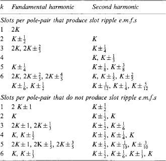
*K is any integer; k is the denominator of the number of slots per pole pair.
In a turbogenerator, the rotor tooth-tops, slot wedges and the damper winding will carry stator-slot-frequency currents. However, the gap-flux ripple at the rotor surface is not great, because the stator slot opening is less than the gap length, except in smaller machines (say below 30 MW). Although q is usually an integer, it usually is more than 6, so the ripple e.m.f. is rarely objectionable.
Walker has also shown that the uniformly spaced rotor bars, in conjunction with integral slots per pole per phase, may cause additional e.m.f. ripples at frequencies of [(N′/p) ± 1]f Hz, where N′ is a whole number given by the rotor circumference divided by the rotor slot pitch. Again this e.m.f. ripple is rarely troublesome.
In summary, design features used to reduce harmonics in the open-circuit e.m.f. are as follows.
(1) Use a fractional slot winding, choosing the number of slots per pole pair from Table 2 of reference 43 (or Table 28.2).
(2) Choose an optimum pole shoe arc, and increase the gap length towards the edges of the pole, to reduce the harmonics in the main flux wave. An arc of 65–70% of the pole pitch is usual, with a gap length at the pole shoes edges 1.3–1.7 times the minimum gap at the pole centre. With fractional slotting, or integral q of 5 or more, a parallel gap will often suffice. This is convenient for solid pole shoes, as it allows the shoes to be skimmed to give the correct rotor diameter after they have been bolted on. With a pole shoe arc of 2/3 of the pole pitch, the third harmonic flux is theoretically zero with a parallel gap, but a graded gap may be chosen to reduce the fifth and seventh harmonics.
(3) Skew the stator slots, or the poles, by one stator slot pitch to reduce the fundamental slot ripple harmonic, or by half a slot pitch for the second order harmonic. Skewing is often used on small machines, but it becomes rather awkward and expensive on large ones.
(4) For a salient pole machine with a whole number of slots per pole pair, offset the damper bars to the left and right alternately on successive poles. An offset of 1/4 of the stator slot pitch each way will largely eliminate the fundamental slot harmonic and will somewhat reduce the second-order harmonic. If necessary, the latter can be reduced further by skewing the stator slots or the damper bars by half a stator slot pitch.
(5) With a whole number of stator slots per pole pair, it may sometimes be worthwhile to offset the poles in pairs to the left and right alternately, in order to avoid ripple caused by slot frequency currents in the field winding. Again, an offset of 1/4 stator slot pitch each way will reduce the fundamental slot ripple.
(6) Make the ratio of the gap length to the width of slot opening as large as other requirements will permit. However, the gap length is governed chiefly by the shortcircuit ratio (approximately 1/Xd) that is specified, and to make it longer merely to reduce slot ripple would usually be unacceptably expensive.
The most effective and economically acceptable methods are to choose a suitable fractional slot winding and shape the pole shoes (for the lower harmonics): or, if an integral slot winding is selected, it is important to choose the most suitable damper bar pitch and to offset the bars as in (4) above.
Stromberg40 explains how the fractional-slot winding reduces the harmonic e.m.f.s, gives reduction factors for various winding arrangements and indicates certain special constructions that can be used if a particularly good e.m.f. waveform is required.
28.3 Alternating current windings
In synchronous generators, the a.c. output winding is on the stator, except in some very small machines and some for particular purposes. For example, the a.c. winding and the diodes of a brushless exciter are necessarily on the rotor.
Low voltage machines with voltages up to 4160 V and with outputs of up to 2500 kVA, may have single- or two-layer windings with mush-type coils wound with round enamelled wire secured in semiclosed slots. Larger machines have two-layer windings using diamond-shaped short-pitched coils wound with insulated rectangular copper strip, secured in open slots. Each coil has one of its sides in the top layer and the other in the bottom. The coils and the connections between them are most often of the lap type but can be of the wave type. See Figure 28.2 for a diagrammatic explanation of these terms. Where such coils would be physically too difficult to manufacture, either because of their size or weight, single half coils, known as bars, are used. Bars may also be of either the lap or wave type. Almost always, in a three-phase winding, each phase-group of coils or bars occupies an arc of exactly or nearly 60° electrical under each pole. As explained previously, the number of slots per phase per pole for the stator winding may either be integral or non integral.
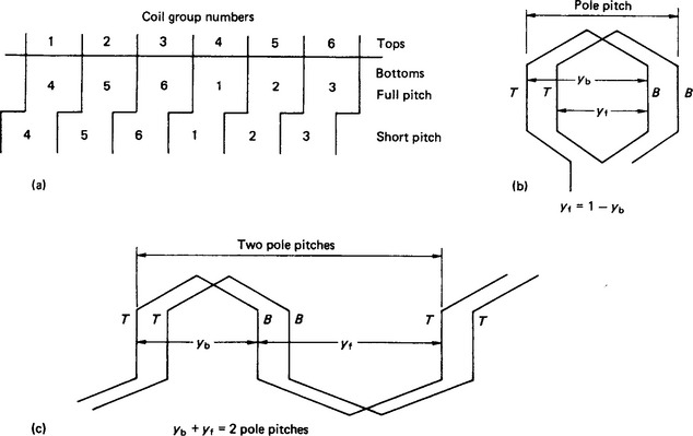
Figure 28.2 Stator coil arrangements: (a) coil groups, q an integer: (b) short-pitched lap connection: (c) short-pitched wave connection
Most two-pole and four-pole turbogenerators use a bar type winding and a whole number of slots per pole per phase. Some large low-speed machines use wave-type windings; smaller machines quite often have skewed stator slots.
The two-layer short-pitched coil winding has the advantages that:
(1) the coils all have the same shape, which reduces the tooling needed for forming and insulating;
(2) a neat endwinding is obtained which is not difficult to support;
(3) the coil span can be chosen to reduce harmonic e.m.f.s produced by flux wave harmonics, and to reduce harmonic m.m.f.s produced by the load current;
(4) fractional slotting can be used, for the same purpose as in (3); and
(5) in multipolar machines, several identical parallel circuits per phase can be formed, giving greater freedom to optimise the design.
Single-layer windings are now rarely used for generators, and are not considered here (see references 11 and 22).
28.3.1 Choice of slot number
Liwschitz-Garik22 gives a very thorough treatment of this subject, to which acknowledgement is given. Considering only three-phase windings, let:
N = total number of slots = total number of coils
See Figure 28.2 for a diagrammatic explanation of these terms Then:
28.3.2 Integral-slot windings
The quantity q can have any practicable value, usually between 2 in multipole machines (though these are more likely to have fractional-slot windings) and 10 in large two-pole turbogenerators. The 6q coils in 6q slots per pole pair are almost always arranged in six groups, each of q coils, each group occupying exactly 60° electrical in each layer. Figure 28.2(a) shows the arrangement of full-pitch and short-pitch coils. The pitch is usually about 5/6 of the pole pitch which is chosen to minimise both the 5th and 7th harmonics.
If the left-hand top-layer conductor of each group is called the ‘start’ of the group, the e.m.f.s acting from start to finish of groups 1 and 4 are 180° out of phase; similarly, for groups 2 and 5, and 3 and 6. Phase A is formed by connecting F1 to F4 to put groups 1 and 4 in series. S1 is the start of phase A, and S4 the finish. Connecting S1 to F4 and F1 to S4 puts the two groups in parallel. Similarly, for phase B (groups 3 and 6) and phase C (groups 5 and 2).
If Phase A starts at slot 1, phase B can start at any slot numbered 1 + 2q + 6nq, and phase C at 1 + 4q + 6nq (2q = 120° and 6ng = 360°, n being any integer from 0 to p).
In a short-pitched wave winding, yb < yf, but yb + yf is equivalent to two pole pitches. The step of 2p × (yr) must be one slot more or less than yf so that a connection can be made to the coil side next to the one at which that tour round the winding started.
28.3.3 Fractional-slot windings
These windings, in which q is not an integer, have the advantage that they can generate as good a waveform with few slots per pole per phase as an integral-q winding with many more slots. Fractional slot windings are frequently used in multipolar machines where there is not room for q to exceed 3 or 4. For example with q = 3 6/7 the effect of harmonics in the gap flux is reduced as effectively as with an integral value of q of 27, an impracticable number. In this example, it would be necessary to have 14, or a multiple of 14 poles to allow the full pattern of groups of coils to be achieved that are required to give an arithmetic average figure of 3 6/7 slots per pole per phase.
Fractional q also gives the designer a wider choice of slot numbers (for most numbers of poles), enabling flux densities to be adjusted more easily on a given frame size.
28.3.3.1 Arrangement of the coil groups
(1) Writing q = a + (b/c) where a, b and c are integers and b and c have no common factor, then c is the least number of pole pitches that will contain a whole number of slots per phase, viz. (ac + b) slots. In the c pole pitches, there are 3(ac + b) coils that form a complete three-phase unit of the winding. 2p/c (= F, say) of these units make up the whole winding, which has N = (2p)/c 3(ac + b) slots and coils (of course N = 6pq).
F is the highest common factor of N and 2p, because
and is the number of slots in the unit that occupies c pole pitches, and c = (2p)/F. Of course N is a multiple of 3 and of F.
(2) A balanced three-phase winding can only be obtained if c is neither 3, nor a multiple of 3. Then, in the c pole pitches in each layer of the winding, each phase occupies b groups of (a + 1) slots, and (c − b) groups of a slots.
(3) Starting from slot 1 of each unit of c pole pitches, the larger and smaller slot groups occur in different sequences in the three phases, but the phase e.m.f.s are balanced. The pattern of larger and smaller groups is the same in all F units.
(4) Taking all three phases together, the pattern of larger and smaller slot-groups is complete in c/3 pole pitches. It occurs 3F times in the whole winding, but does not itself form a balanced three-phase unit.
(5) The sequence of a-slot and (a + 1)-slot groups can be found as follows which is the same for lap as for wave windings.
60° electrical contains q slot pitches. Starting from 0° at slot number 1, the centre lines of the first and last slots of successive slot groups (often called phase belts) must lie within the electrical angles 0–60°, 60–120° …, 420–480°, etc., from slot 1. Therefore, the centre line of the last slot of the n th group lies just within nq slot pitches of slot 1, where n is an integer. In general, nq is an integer plus a fraction, say nq = n (ac + b)/c = X + (Y/c). Then, the slot number (1 + X) is the last slot of the n th group. But when n = c, 2c, etc., X = (ac + b), 2(ac + b), etc., and Y = 0. Then slot number (1 + X) lies exactly 60n° from slot 1, and so is the first slot of the (n + 1)th group. Table 28.3 illustrates the method for a 12-pole machine with 135 slots, q = 3/4, c = 4, and F = 3. The slot sequence 4, 4, 4, 3 can be determined by considering only c steps of q slots but the complete table allocates all slot numbers to phases.
Table 28.3
Slot, or coil, grouping for a fractional slot winding*
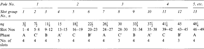
Top coilsides 1–4, 13–15, 24–27, 35–38, with their associated bottoms, form one parallel circuit of phase A.
*12 poles. 135 slots, q = 3 3/4 slots/phase/pole, c = 4 poles per section, F = 3 sections.
The fraction b/c determines the numbers of larger and smaller coil groups and their sequence in the winding. References 8 and 22 contain tables of coil group sequences for a wide range of values of b/c.
(6) Within the c pole pitches of the repeatable unit all the conductors of a phase have different positions relative to the poles. Thus their e.m.f.s are out of phase, and all the cq coils must be connected in series. But the e.m.f.s of the F units of a phase are in phase, and can be put in parallel if necessary (see Section 28.3.4).
(7) 2q slot pitches span 120°, but the smallest integral number of pitches covering 120° is 2cq. Slots spaced at multiples of 2cq pitches are the obvious starting slots for phases A, B and C. In the example, slot 31 is 120°, and slot 16 is 240° from slot 1. But as with q an integer, the starts can be at other phase groups that are 2 or (2 + 6n) phase groups apart; e.g. phase B could start at slot 9, although that is 128° away from slot 1. The sum of the coil e.m.f.s is independent of the order in which they are connected (so long as the polarities are kept correct). Starts and finishes can therefore be arranged in the most convenient positions. This can be used to advantage to ensure that the leads from each phase group are distributed around the machine, thus avoiding two adjacent leads having full line-to-line potential between them.
(8) The bottom coil sides have the same pattern as the tops but their groups are displaced to the left or right by the amount of the coil pitch.
(9) Sometimes multipolar windings are used that do not obey all these rules; for example, an existing core design may be usable with a few empty slots or unconnected coils.8,11, 22
28.3.4 Parallel circuits
28.3.4.1 Integral slot windings
Each phase has two groups of coils per pole pair, i.e. there are 2p groups in the machine. Whether the coils are lap or wave connected, the groups can all be put in series, all in parallel, or in series-parallel connection. For the latter, the number of parallel circuits in each phase must be a factor of 2p, say t, so that there can be 2p/t groups in series in each parallel path. For example, for 2p = 10, only two or five parallel circuits are possible.
28.3.4.2 Fractional slot windings
In each repeatable section, occupying c pole pitches, the ac + b coils of each phase must be put in series. Hence the maximum number of parallels per phase is the number of sections F = (2p)/c. If less are needed, their number must be a factor of (2p)/c, so that there will be 2p/ct repeatable sections in series in each parallel path. For example, for 2p = 40 and q = 2 1/5, there are 40/5 = 8 repeatable sections and 2, 4 or 8 parallels are possible. With 2p = 40, but q = 2 1/4, (2p)/c = 10, only two or five parallels are possible.
28.3.4.3 Concentrated or distributed parallel circuits
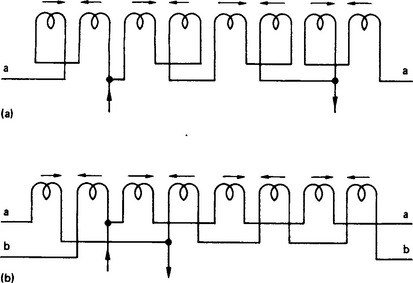
Whether q is integral or fractional, in each parallel circuit the coils that are in series may be arranged under adjacent poles, or may be distributed around the machine under alternate poles. Figure 28.3 shows two possible arrangements for two parallel circuits in one phase of an eight-pole winding. The concentrated arrangement shown in Figure 28.3(a) has the advantage that it reduces the unbalanced magnetic pull caused if the rotor is offset radially from the true centre of the stator bore. If, for example, in this 8 pole machine, the airgap becomes narrower opposite pole 2, the gap flux density tends to increase there, and to decrease opposite pole 6. The change in induced e.m.f.s circulates current round the parallel circuits, which tends to reduce the difference in flux densities and so reduce the unbalanced magnetic pull (u.m.p.).
28.4 Coils and insulation
The effects that may eventually cause a breakdown of the insulation of a winding are described below.
Thermal ageing: This affects all windings, and is the main reason for setting limits for winding temperature (see Section 28.5). In smaller machines running at full class H temperatures it is the most usual cause of deterioration.
Electrical stress: The trend in stress levels is continually upwards as manufacturers seek to minimise costs and reduce the effect of the thermal barrier of the insulation which is a factor in determining a machine’s output. This requires considerable care in the design of the insulation system, in the manufacture of the coils and their insertion in the stator slots. Values of 3 kV/mm are now common with even higher figures being achieved by some manufacturers. The voltages encountered in field windings increase with machine size up to ceiling voltages (see Section 28.14) of around 1500 V on the largest generators. Thyristor excitation systems also superimpose spike voltages sometimes requiring extra insulation.
Electromagnetic forces: Stator and field coils are both subjected to forces due to the magnetic fields operating in the machine. Any looseness of an a.c. winding in its slot will quickly lead to mechanical abrasion of the insulation on the coils. On higher voltage machines, equipped with a corona shield, this will lead to slot discharge with eventual failure of the main wall of the insulation causing an earth fault in the slot portion. Field coils able to move on their poles or in their slots will also lead to failure through abrasion.
Mechanical forces: Rotor windings carry centrifugal forces that become very onerous in high speed and large machines. Interturn insulation and coil-to-earth insulation placed under the pole shoe and adjacent to supporting ‘V’ blocks used between poles must withstand the stress caused by centrifugal force and temperature. Non-supported parts of the winding, between ‘V’ blocks and in the endwinding overhangs are particulaly vulnerable especially in the event of an overspeed. In long rotors, especially two-pole turbine-type rotors, expansion of the winding relative to the rotor body may damage the insulation. Stator windings of long machines may also suffer from differential expansion between the copper and the core. In large generators double frequency vibration caused by electromagnetic forces may abrade insulation or even cause conductor strands to break due to fatigue.
Vibration: External vibration, imparted by the prime mover can lead to premature failure of the stator or rotor. In the case of the stator this results from lateral vibrations setting up resonance or fatigue in mechanical components or in the endwinding bracing system. Rotor failures are associated with the effect of running at or near the critical speed of the shaft system leading to high levels of vibration or high tortional perturbations leading to fatigue failures of components.
External electrical fault conditions: Mal-synchronising, line-to-line faults or short duration interruptions of the supply can all impart high mechanical and electrical forces on both the stator and rotor windings. Under these conditions, mechanical failure of the stator endwinding bracing, looseness of the winding in the slot or separation of the phase groups can all occur. Rotor field coils suffer from mechanical forces under these faults which can lead to coil connection failures, failure of the insulation or damge to components in the rectifier assembly if a brushlesss machine. Lightning strikes and switching transients arising from the operation of circuit breakers can also lead to failure of the inter-turn insulation in the end groups of the stator windings if the machine is not suitably protected by lightning arresters and/or surge diverters. Similarly, opening a field circuit breaker without suitable discharge resistors fitted can give rise to very high voltages of sufficent magnitude to break down the field coil insulation.
28.4.2 Stator coils5,11,22,53
The various types of stator coils most used for generators are described below. The type used depends primarily on the size, output and voltage of the generator, but the choice is, of course, influenced by the maker’s facilities and practice.
28.4.2.1 Mush coils
These are used for smaller machines, up to 2500 kVA, at voltages up to 4160 V, in single layer or two-layer windings. Coils are wound with round wire insulated with enamel or enamel and glass tape. The number of turns per coil depends on the size, voltage and frequency of the machine, and the chosen number of slots. The turns are laid at random in slots that may be open, but are often semi-closed, especially if the airgap is short. The main insulation between the coil and the core is a slot liner of a tough but sufficiently flexible sheet, such as polyamide or aramid paper (Nomex). Two-layer windings may have a separate liner for the top and/or bottom coil side (a top or bottom ‘box’) or a separator between the coils.
28.4.2.2 Diamond coils
These are arranged in two layers in open slots and used for a wide range of outputs and voltages. Coils are wound with rectangular copper strip that is small enough to have acceptably low eddy current losses in service. Sizes are usually within the range 5 mm × 2 mm to 10 mm × 4 mm. The strip is insulated with enamel or enamel plus a thin covering (say 0.2 mm) of lapped or braided glass or polyester-glass plus resin. The number of turns needed are wound into a flat loop on a looping machine and the straight sides are then pulled sideways to form a coil with the required axial length and transverse span. Depending on the equipment used, strip up to about 10 mm wide by 4 mm deep can be pulled. The width-to-thickness ratio should not much exceed 3, to avoid buckling at the bends. If necessary, several strips are wound in parallel to provide the conductor area needed to carry the current, or to make the coil flexible enough to be pulled without damaging the insulation.
Normally a coil has either one or two strips across the width of the slot. Additional inter-turn insulation, enclosing the number of strips that form a complete conductor may be applied after the coil is pulled. However, it is often practicable to apply this insulation as the copper strips are wound on the looping machine, provided that the insulation contains enough resin (see later).
Coils too large to be pulled are shaped on formers. Those for turbogenerators and large hydrogenerators are made as half coils (also known as ‘bars’) because full coils would be too difficult to handle. In addition, coils made for large 2-pole machines are exceedingly stiff and are difficult to insert through the bore of the machine. Figure 28.4 shows typical coil cross-sections, all to the same scale. Figure 28.4(a) shows a typical pulled diamond coil for a diesel-engine-driven 14-pole generator of 9.5 MVA where the conductor strands are not transposed. The coils in (b) and (c) are formed as bars and incorporate a Roebel transposition which is used to reduce the eddy currents circulating within the full coil (see para 28.4.2.3. below). Coil (b) is for a hydrogenerator of 110 MVA at 600 rev/min and (c) is for a 590 MVA two-pole turbogenerator. In (c) all the strands are squarish tubes to allow for direct water cooling of the conductors: a mixture of tubes and solid strips is often used, especially for the bottom coil side, where eddy current losses are lower than in the top coil side. An appropriate choice of the number and dimensions of tubes and strips can lead to a reduction in the sum of d.c. and a.c. copper losses.
28.4.2.3 Transposition51,52
If each turn consists of more than six or eight strips it is desirable, and in larger conductors necessary, to reduce the eddy current losses set up by the leakage flux set up across the slots by the load current. In principle this requires the e.m.f.s induced by the leakage flux to be equal in all strips in the length between points where they are all joined together. In a multistrip coil side for a turbogenerator or hydro-generator this is achieved within each slot length by using a 360° Roebel transposition. In this construction, each strip is given two edgewise bends separated by half the slot length and differently positioned in the various strips so that when assembled the strips mesh together. When the strips are assembled to form the coil side, each strip occupies each position in the height in turn and they all do so for equal distances. Hence the voltages induced by the cross-slot flux is equal in each and only a small current circulates between strips due to endwinding leakage fields.
In large generators (say 500 MVA or more) the endwinding leakage fields can cause significant circulating currents. The effect can be reduced by using a 540° Roebel transposition. This reverses the positions of the strips in one end-winding relative to the other and approximately cancels the e.m.f.s. arising from the endwinding leakage fields.
In all Roebel coils, the radius of the edgewise bends must be sufficiently generous to avoid damage to the strip insulation. Usually a slip of, for example, Nomex is placed between strips at the cross-overs. The undulating top and bottom surfaces are made level by applying a suitable filler, such as a filled resin dough, which is cured when the conductor stacks are consolidated, before the main insulation wall is applied.
Large turbogenerator slots are often wide enough to require four, not two, stacks of tubes, or strips and tubes. The eddy current losses are rather less if stack 2 is transposed with stack 3, and stack 1 with stack 4, rather than 1 with 2 and 3 with 4. For smaller bars with relatively few strips, and for full coils, the Roebel transposition in the slot is not justified: simpler schemes are possible which are sufficently effective in reducing circulating losses. For example, in a bar winding individual strips can be joined at the coil-to-coil connections in insulated, segregated groups, not all together as is done with a Roebel bar winding. The strips are joined so that within a phase group of coils the groups of strips occupy a succession of positions in the slots that gives a sufficiently good balance of leakage flux e.m.f.s.
With full coils the natural roll-over of the conductors at the noses inverts the strips, i.e. a strip nearest the wedge in the top coil side is nearest the slot bottom in the bottom coil side. Summers52 gives formulae for calculating the reduced circulating current loss that can be obtained by additionally inverting one or more turns in the overhang portion. He concludes that the most generally useful arrangement is to invert the strips of one turn only at the connection end before forming the last turn; or to invert them at the back end after making only the first half-turn. These sorts of transposition are only effective on 2 or 3 turn coils—above this number it is not necessary to incorporate a transposition in the coil overhangs to reduce the circulating losses to an acceptable value.
28.4.3 High voltage insulation systems53,58–61
Two systems60 are in general use: resin rich (r.r.) and vacuum pressure impregnation (v.p.i.). Both use mica paper (mica flake, which was universally used until the early 1960s, is very rarely used today). The mica paper is bonded with a thermosetting resin to a thin backing material,54 frequently woven glass or polyester fabric or polyester film. Polyester, epoxy and epoxy-novolac resins, or mixtures of them, are most widely used for r.r. and v.p.i. systems, with appropriate hardeners and catalysts to control the curing process. Resin rich tapes contain about 30% resin, dried to the B stage, at which it can be stored in cold conditions (5–10°C) long enough to be convenient in manufacture. It can be applied at room temperature by hand or by a taping machine; the machine gives better control of lapping and tension. Resin rich tape can be applied as additional turn insulation56 to a group of strips that is then wound and pulled to form a coil of several turns. Tape for the v.p.i. process contains 4–10% of a different resin system to make it handable and is more fragile than the resin rich tape.
Normally, the strips in the straight sides of the coil, or in the bar, are consolidated in a heated press before any turn insulation or main wall insulation is applied. If the turn insulation (r.r.) has been applied as the pulled-coil loop was wound, this and the strips are cured and bonded at the same time. If turn taping is to applied after this consolidation stage, a release film is put between turns to allow the additional taping to be applied. After any turn taping and the main wall insulation has been applied, the slot portion of the coil is again consolidated under heat and pressure to cure the resin contained in the mica tapes. For turbogenerators and large-hydrogenerators the endwinding portions are consolidated too, both before and after the insulation is applied to improve their thermal conductivity.
In the v.p.i.59 process, the low-resin content mica paper is applied after the conductor strips have been consolidated. If individual coils or bars are being manufactured, these are placed in an autoclave. Air is drawn out of the tape under vacuum in the autoclave, which is then flooded with low-viscosity resin under pressure. After impregnation, excess resin is drained off, and the coil is pressed to size in a hot press.
Alternatively, for machines up to 5.3 m in diameter and 5 m in length (dependent on the manufacturer’s facilities) the global v.p.i. impregnation process can be used.57 Here, the coils are wound at the so-called ‘white stage’ into the stator core and the whole wound stator is then placed in a suitable pressure vessel. Absorbent packings and lashings are used in the endwinding bracing structure (e.g. glass or polyester tapes and polyester fleece). Again, a vacuum is drawn to remove any air trapped in the insulation materials followed by a pressure cycle where resin is introduced. Following impregnation, the wound stator is immediately transferred to an oven where it is baked to cure the resin. If treated with an epoxy resin, the stator would be rotated during the baking cycle to ensure both an even distribution and retention of the resin. Stators impregnated with a polyester resin do not require rotation during the curing cycle as the resin gels before becoming sufficently fluid to flow out of the stator. The resin fills the gap between the coils and the core, improving thermal conductivity and permitting some increase in current for a given temperature rise in service. Complete impregnation of the endwinding structure increases its strength and its resistance to moisture, dirt and contaminants.
The r.r. and v.p.i. processes can both produce good quality stator insulation systems. Essentials to achieve a high level of quality are:
(1) uniform lapping and tension of all tapes;
(2) correct choice of resin, tapes etc., to suit the process;
(3) r.r. tapes must be allowed to warm up to room temperature before being applied;
(4) v.p.i. resin must have a low enough viscosity at the impregnating temperature, and an economic life over many cycles of storage and impregnation;
(5) careful control of each cycle of the processes to ensure sound consistent results. In the consolidation stages, the soaking temperature (about 150°C), the heating and cooling rates, and the application of pressure all need careful control. During the v.p.i. process, times, temperatures, the degree of vacuum and the amount of pressure are all critical to achieving a satisfactory result.
28.4.3.1 Electric stress control
At line voltages up to about 5 kV the insulation material and thickness depend very much on mechanical and manufacturing factors. The nominal stress (phase voltage divided by insulation thickness) may be up to about 1.5kV/mm. At higher voltages electrical stress determines the design, and nominal stress on resin-mica systems is usually 2.5 to 3.0kV/mm.
At or above 6 kV, the outer surface of the slot part of the coil (whether r.r. or v.p.i.) must be adequately earthed to the stator core to avoid corona discharge in the gap between coil and core. This gap occurs because of the need to have a clearance to allow the coils (or bars) to be wound. The surface may be painted with a conducting paint, but preferably should be taped with a low resistance tape, e.g. a graphite loaded glass or polyester, before the final consolidating press. At the ends of the core the longitudinal stress gradient along the coil surface must be kept low enough to avoid breakdown of the air or surface tracking and eventual failure of the insulation. The surface may be painted with a higher resistance paint than is used on the slot part, but preferably is taped with, for example, a tape loaded with silicon carbide. The length of this stress grading treatment depends on the machine voltage, the insulation thickness and the voltage-current characteristic of the material used. (The resistance decreases with increasing stress.) The treatment must be effective for the short-time high-voltage tests on the coils (greater than twice line voltage to earth) as well as for the long-term operating voltage.
28.4.4 Insulation testing
Acceptance tests66 are made on the finished generator to prove that it meets contractual requirements. Tests include:
(1) d.c. insulation resistance (IR), recorded after applying the test voltage continuously for 1 and 10 min;
(3) high-voltage test with, usually, power frequency voltage, applied after satisfactory IR and PI results have been obtained. The test voltage is maintained for 1 min between each phase and earth in turn, the other phases being earthed.
Procedures and test voltages are specified in BS EN 60034-1:1998 which is equivalent to IEC 60034-1:1994 and replaces BS 4999: Part 101:1987, in ANSI C50.10 1990, NEMA MG1: Part 32-1998, and other national specifications. (see Section 28.21.) The latest issue of the appropriate specification should be consulted for complete information; broadly, the test voltages are, except for low-voltage machines rated less than about 1 kW:
A.c. windings: 2 × rated line voltage + 1000 V.
Document BS EN 50209:1999 specifies tests on conductor bars and coils for machines with rated voltage UN from 5 to 24 kV. Tests include: (1) measurement of loss tangent (tan δ) and loss tangent tip-up (Δ tan δ) on all or some coils of a machine set; and (2) voltage tests on the strand insulation, turn insulation and main insulation. The specification applies to generators of 5 MVA and above, and to 1–5 MVA ratings by agreement. It may or may not be specified as a contractual requirement. The tan 6 limits are, for rated voltages UN of 5–11 kV inclusive:
(1) at 0.2 UN, tan δ not greater than 30 × 10−3 for any sample coil or bar;
Limits (2) and (3) apply to 95% of the test samples; 5% are acceptable at 3 × 10⁻³ for item (2) and 6 × 10⁻³ for item (3).
The measurements must be made at room temperature before the samples are heated to at least 90°C, and again after they have cooled to room temperature. Guard electrodes at the ends of the slot length of the bar exclude the loss in the stress grading from the measurement. R.r. and v.p.i. systems can comfortably meet these limits. Typical values are:
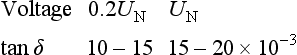
Most of the increase occurs between 0.8 UN and UN. Of course tan δ of a globally impregnated winding can only be measured on complete phases, and the limits stated above cannot apply; comparison with individual coils is necessary.
28.4.4.2 Quality assurance tests
Quality assurance tests are made at the manufacturer’s discretion at suitable stages of manufacture. They include:
(1) Dimensional, mechanical and dielectric tests on incoming materials.
(a) between insulated strands in a conductor, at 110–250 V r.m.s.;
(b) between turns of multi-turn coils;
(c) on individual coils or bars;
(d) on groups of coils after they have been wedged in the slots, but not connected; and
(e) on each phase of the completed winding before the acceptance tests.
Supply frequency voltages in (c) and (d) and (e) must be rather higher than the final test voltage; (b) must be an impulse test unless the turns are cut through at the coil nose: it is obviously undesirable to cut a full-wound coil, so a Biddle or other surge tester is used.
BS EN 60034-15:1996 specifies rated phase-to-earth impulse withstand voltages for machines rated 3–15 kV inclusive, with form-wound coils. For the standard lightning impulse, a 1.2/50 μs wave, the rated impulse voltage has a peak value Up = 4UN + 5 kV, where UN is the rated voltage. The standard recommends that impulse test voltages should not be applied to a complete machine. It describes test procedures on sample coils, and specifies test levels of (4UN + 5) kilovolts between the conductor and a dummy slot, and half that value between turns, i.e. applied across the ends of the coil.
International discussions are being held to agree upon a withstand level for impulse voltages with steeper wavefronts probably down to rise time of 0.2 μs. In service many generators are protected to some extent from impulse voltages by the impedances of transformers or cables. These reduce the peak voltage and steepness of the wavefront. so the generator does not suffer the full impulse generated by some forms of switchgear. Alternatively, lightning arresters and/or surge diverters may be fitted at the machine terminals to protect the stator windings from fast fronted surges.
(3) IR and PI measurements before (2)(d) and (2)(e).
(a) tan δ test on all or some coils or bars.
(b) tan δ test on each phase of the complete winding and between phases before impregnation.
(5) Measurement of integrated discharge magnitude using a dielectric loss analyser,69 on individual coils, phases and the complete winding.
(6) Measurement of the partial discharge value on individual phases or the complete winding.
(7) Measurement of the resistance per square of the corona shield on the slot part of the coil: 2–30 kΩ/square is acceptable.
28.4.4.3 Diagnostic tests in service67–70,79–82
The electrical, mechanical and thermal stresses of normal service cause gradual degradation of the insulation. If this general deterioration can be adequately monitored, preventive maintenance of the winding can be co-ordinated with other planned maintenance in an attempt to avoid the cost of failures and unplanned outages. It is true that some generators work in less harsh environments than some motors do, or have closed air circuit cooling arrangements so suffer less contamination, but the cost of an unplanned outage or the damage caused through inadequate maintenance can be appreciably higher. Consequently, more and more attention is now being placed on the need for continuous on-line monitoring and preventative maintenace based on regular inspections for generating plant.
No single test can indicate the extent of deterioration at a particular time. It is necessary to review the results of several non-destructive tests made at reasonably regular intervals, preferably starting with a ‘foot-print’ from when the machine was first manufactured.
Simons69 recommends measurements of:
(1) IR and PI with direct voltage at say 1, 2.5, 5.0 kV, appropriate to the machine’s rated voltage UN (r.m.s.):
(2) IR, capacitance C to earth, and integrated discharge energy at rated frequency (50 or 60 Hz) with voltages up to UN to earth; and
(3) C and tan δ at steps of 0.2 UN up to about UN to earth. Tests are made, as usual, on each phase to earth with the other phases earthed, and on the whole winding to earth.
A local defect, unless it is a severe one, will not greatly affect the results. It may, therefore, be desirable to apply a proof h.v. test at say 1.2–1.5 UN (r.m.s.) to earth at supply frequency, or a 0.1 Hz voltage with a peak of 1.7 UN (r.m.s.).
28.5 Temperature rise
Limits of temperature or of temperature rise are specified in national and international standards (see Section 28.21: BS EN 60034-1:1998, BS EN 60034-3:1996, ANSI C50: Parts 10–15 and NEMA MG1: Part 32).
The limiting values apply at rated load under specified ambient conditions, of which the most important figure is the temperature of the primary coolant (air, hydrogen or water) entering the machine or the winding. Temperatures of stator windings are measured either by resistance for machines rated below 5 MVA, or by embedded temperature detectors (e.t.d.), either of the thermocouple or resistance element type, above this rating or when supplied to NEMA MG1. Temperatures of rotating windings, usually field windings, are measured by resistance. In small machines without e.t.d.s fitted, winding resistance or surface temperatures would be measured on test, and monitoring in service may be of air temperature only. Temperature rises are calculated above the temperature of the primary coolant. Alternatively, but less often, it may be calculated above the temperature of the cooling water entering a heat exchanger.
Machines are designed to comply with the temperature rise limits specified as long as the primary coolant temperature does not exceed 40°C. If the ambient air temperature is high, or there is a water-cooled heat exchanger, the primary coolant temperature may exceed 40°C. Then the design rises are correspondingly reduced, so that the limiting total temperatures are not exceeded. This is especially likely to occur with turbogenerators using turbine condensate, which may enter the heat exchanger at a temperature of up to about 35°C. Conversely, if the temperature of the primary coolant entering the machine is less than 40°C, then the standards allow the temperature rises to be adjusted upwards to maintain the same total temperature. Below a primary coolant temperature of 30°C, any further adjustment is by agreement between the customer and the supplier.
The aim of all standards is to keep the temperature of the winding insulation down to a value at which the insulation, and therefore the generator, will have an acceptably long life. Standards do not specify or imply a lifetime. Accepted norms for life are 20 years for large capital equipment installed in prime power applications. A life expectancy of 10 years is more appropriate for industrial and smaller units. Some machines last much longer than these figures partly because they do not operate for long times near their temperature limits. Large machines or those subject to frequent load changes, or whose reliability is especially important, are commonly specified to meet class B temperature limits, although they have class F insulation in order to achieve a protracted life.
In all windings, the design must allow for the difference between the observable temperature and the hotspot temperature that ages the insulation most rapidly. In an indirectly cooled high voltage stator coil this difference may be 10–20 K, and the innermost insulation may run close to the classification temperature for the insulation system (130°C for class B and 155°C for class F). In an indirectly cooled turbogenerator rotor too, the temperature difference across the main slot insulation is a major component, but the temperature rise of the gas in the ‘air’ gap, and the surface-to-gas temperature difference, are important. In a salient-pole rotor, the end parts of bare strip-on-edge field coils are well cooled, but down the length of the coils turns can overheat, especially on four- to eight-pole rotors that have ‘V block coil supports between the poles.
Direct cooling avoids the temperature drops through the insulation, and permits higher current densities with acceptable temperature rises, e.g. up to about 10 A/mm2 in a turbogenerator rotor hydrogen cooled at 5 bar absolute pressure, compared with about 3 A/mm2 with indirect air cooling. Axially cooled rotors, with ends-to-middle gas flow, must have a modest temperature rise by resistance to avoid excessive temperatures at the midlength. Radial flow, or a combination of radial and axial, gives a mean temperature closer to the permissible hotspot temperature.
In a directly cooled stator coil the best indication of copper temperature is given by the temperature of the coolant, hydrogen or water, where it leaves the coil. The copper temperature is up to about 10 K higher than the hydrogen temperature, and only approximately 1 K above the water. The traditional e.t.d. between coil sides is still used as the routine temperature indicator in service, though some turbo generators are instrumented to measure the outlet temperature of the water from every coil. (For stator windings in new turbogenerators, water has superseded hydrogen, and it is the only choice for hydroelectric generators.) If the water flow fails the copper temperature rises very quickly, say 20 K/min, so the turbine output should be automatically reduced to avoid gross overheating and failure of insulation.
Gas turbine driven generators (see Section 28.21: BS 5000: Part 2 and ANSI C50: Part 14) are specified differently from others because the maximum output available from the turbine changes quite widely as the inlet air temperature changes. The generator must deliver the range of outputs that is the base capability of the turbine over the whole range of air temperature. If the generator is cooled by ambient air, and is allowed to operate up to limits of total temperature, the changing temperature rise allowed as the air temperature changes gives the generator a capability that matches that of the turbine more closely than if the rise were fixed at the rated-load value at all loads and ambient temperatures. Hence a smaller and cheaper generator can be used to cover the turbine rating across the operating temperature range.
The range of still higher outputs that is the peak capability of a gas turbine or internal combustion engine is handled by allowing higher total temperatures in the generator. At these, the insulation ages much more quickly than at standard temperatures. This is accepted because: (1) peak operation demands more frequent engine or turbine maintenance, so will not be used frequently or for long periods, and (2) many internal combustion engine or gas-turbine-driven sets are not expected to have a life of 10 years or more.
If a gas turbine driven generator has water-cooled heat exchangers, its range of permissible temperature rise will probably be less than the ambient air range due to the long thermal time constant of the source of the cooling water. The capability of the generator no longer matches the turbine output so closely and its frame size and design details are determined by the maximum turbine output but using the primary coolant temperature corresponding to the minimum cooling water temperature.
28.6 Output equation
The generator output in apparent power (S volt-amperes) is a function of the stator bore diameter D, the active axial length L, the speed n, the specific magnetic loading B, the specific electric loading A, and the stator winding factor Kw. The output is given by
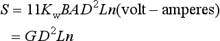
where G is the output coefficient ((V-A s)/m3), B is the average fundamental frequency airgap flux density ((2pΦ)/(πDL) tesla), 2p is the number of poles, A is the ampere-conductor density ((IcN)/(πD) ampere/metre), where N is the total number of stator conductors = 2Tph × number of phases, or number of slots × conductors per slot, Ic is the current in each conductor (= phase current/g amps), n is the speed in (rev/s), g is the number of parallel circuits per phase and 11 is a numerical multiplier when all dimensions are in metres. Kw is the product of the individual winding factors. (KdKpKs) and ϕ, is the fundamental component of the flux per pole (in webers).
The stator winding is designed to develop the specified voltage with B and A close to chosen values. For different types and sizes of generator, B does not vary widely: it is limited primarily by the degree of saturation that is acceptable in the various parts of the magnetic circuit. Typical values of B are in the range 0.5–0.65 T on no load, corresponding to peak densities in the airgap of say 0.7 to 0.95 T. On load the increase of total flux and the distortion caused by armature reaction will cause the peak density to rise by about 15–20%.
The electrical loading A varies very widely with size and with the intensity of cooling, short-circuit ratio, reactances, etc.
G is numerically more convenient if expressed as
i.e. in (kV-A min)/m3. Figure 28.5 gives typical mean values of G against rated MVA; the values range from 5 to 35, but variations can easily be ± 15% for a given output. With G in (kV-A min)/m3, A is approximately (6G)/B kA/m. Assuming B = 0.6 T, A ranges from 50 to 350 kA/m.27
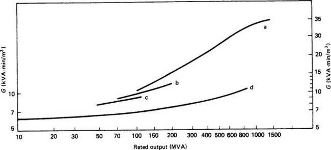
Figure 28.5 Output coefficients, G. Turbine generators: (a) directly hydrogen cooled + stator winding water; (b) directly air cooled; (c) indirectly hydrogen cooled; (d) salient-pole generator
The steady increase in G for salient pole generators is a result of the scale effect and progressive improvements in design, mainly in more effective cooling of the stator and field windings. For turbogenerators, a sharp increase in G occurred in the 1950s with the introduction of direct cooled rotor windings using hydrogen at 3 bar absolute pressure. Rapid increase in unit ratings and in G soon occurred, using hydrogen at pressures up to 5 bar absolute and improved methods of circulating it through the windings. It was necessary also to improve stator cooling in order to handle the higher capability of the rotor. Water cooled stator windings have been universally adopted for machines of say 200 MW or more, although direct hydrogen cooling had been used for many stator windings up to 800 MVA output.
In recent years the demand for electric power has grown steadily at the rate of 5% per annum though there has been much public outcry against nuclear power and against acid rain from large fossil-fired stations. Hence there has been almost no call for turbogenerators larger than 500 MW recently, though the recent power shortages on the west coast of America and the insatiable demand for power both in the developing and the developed nations means that there is now renewed interest in nuclear power to meet those needs. In order to maximise efficiency and to satisfy the economics of building nuclear power stations, large generator units possibly up to 1500 MW may well be required in the near future. In recent years, there has been a large number of combined heat and power (CHP) systems have been installed. Here the waste heat from the prime mover, which may be a gas or diesel internal combustion engine or a gas turbine is used for a supplementary purpose such as district heating. This has the effect of increasing the efficiency of the power station. Another possibility to achieve enhanced efficiency has been the use of combined cycle systems where the exhaust gases from a gas turbine are used to raise the steam to be used in a steam turbine located alongside or on the same shaft as the gas turbine. These schemes require generators with ratings up to 150–200 MW at 3000 or 3600 rev/min. For low first cost, and for cheap installation and operation, air-cooled machines have been developed using directly cooled rotors, reaching output coefficients exceeding those of the early low hydrogen pressure machines.
28.6.1 Some design parameters
28.6.1.1 Specifed requirements
Appendix B of BS EN 60034–1:1998 lists information that should be supplied to the manufacturer.
A generator is required to meet specified values of output (kilovolt-amperes, voltage, and power factor) at a specified speed under stated operating conditions, of which the cooling conditions are most important. Specified limits of temperature rise or of total temperature must not be exceeded. The machine must maintain the performance during a life that is specified (or understood by custom and practice), and should do so with reasonable maintenance but without needing major repair. Normally a maximum value of Xd (or a minimum short-circuit ratio) is specified. A minimum X″d and or a maximum X′d may also be specified if currents under fault conditions are to be limited to a certain value or if voltage dips when starting specified loads are to be limited. National specifications recommend preferred voltages (e.g. ANSI C50: Parts 12, 13 and 14), but for large units connected by transformers to the system the generator voltage can be chosen to give the most suitable design.
28.6.1.2 Length to diameter (L/D) ratio
For two- and four-pole cylindrical rotor machines the cheapest design is usually one using the smallest diameter that does not lead to excessive length. The ratio usually lies in the range 3.5–6, perhaps up to 7 for the largest outputs (over 1000 MW) where the strength of retaining ring material limits the diameter to a surface speed of about 220 m/s (1.35 m diameter at 3000 rev/min). With such ratios, two-pole rotors for more than about 10 MW will have first and second critical speeds below the running speed. Higher ratios are avoided because they would lower the critical speed still more and make the rotor very sensitive to small (e.g. thermal) changes in balance.93
Cooling also becomes more difficult in very long machines. Salient pole machines with four poles and outputs of, say, 3–30 MVA may have a L/D close to unity but, because there are so many combinations of output, speed, overspeed, reactance, inertia, etc., no simple rule can cover the whole range of outputs. The ratio of L to pole pitch varies rather less than L/D, but still runs from 2.5 to 6 for outputs in the range 150–800 MVA, associated with speeds in the range 500 to 83 rev/min.
28.6.1.3 Stator winding
The most suitable type of winding is usually obvious from the specified current and voltage and the manufacturer’s established practice (see Sections 28.3 and 28.4). The cost of making and installing the winding will be smaller the fewer the coils, but too few will cause difficulties. The current per slot, and the copper cross-sectional area, must be such that specified temperature rises are not exceeded. With too few slots, they are necessarily wide, and the total loss per slot may cause excessive temperature rise. With too many slots (and coils) they become narrow and deep, and much slot space is used for insulation; the coils are awkward to form and to support effectively in the endwinding. The ratio of slot depth to width should preferably not exceed 7 (4–6 is usual).
The ratio of slot width to airgap length should be about 1 1/2 to 2 with solid pole shoes; with laminated shoes or poles 2 1/2 to 3 1/2 is permissible. Higher ratios increase the tooth ripple e.m.f., and the eddy current losses in the pole surface.32,33 This is particularly important in salient pole machines with short airgaps especially machines with solid pole shoes. In turbogenerators the airgap is so long that this effect is rarely troublesome.
The tooth width must be enough to avoid excessive magnetic saturation on load, allowing for the radial vent ducts in the core. Roughly, the width of the tooth tip is about half the slot pitch.
28.6.1.4 Short-circuit ratio, synchronous reactance, and rotor temperature rise
The short-circuit ratio (SCR) and Xd are defined with reference to Figure 28.10.
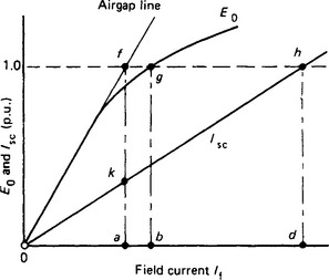
where SF is a saturation factor, ![]()
which usually has a value between 1.1 and 1.2. Xd is almost inversely proportional to the length of the airgap, and the SCR is approximately directly proportional to the length, lg
Changing lg adjusts SCR and Xd, but has only a small effect on other reactances.
For a given output and frame size, increased SCR requires increased excitation, especially if the length of the airgap is increased to raise the SCR, which may cause excessive field temperature rise. Then, unless the cooling can be improved, a lower electrical loading or a larger frame size becomes necessary.
Evidently, a lower SCR permits more output from a given frame size which will be determined by the thermal limit set by the rotor: of course the stator must also be adequately cooled.
As turbogenerator ratings increased, lower values of SCR came to be accepted, partly as a matter of necessity to restrain the increase in physical size, but largely because faster control of excitation and of turbine valves, and shorter fault-clearing times, made it possible to operate safely closer to the stability limit. SCRs fell from the usual range of 0.8–0.6 to 0.6–0.45 for turbogenerators.
Hydrogenerators too have benefited from improved excitation control, power system stabilisers and faster clearing times, but are still required to supply a higher line-charging capability than most turbogenerators. Their SCRs are therefore usually in the range of 0.8–1.5. Other salient pole generators up to say 40 MW (see Section 28.18) have an SCR usually between 0.5 and 0.8. with some up to 1.0 for particular locations.
28.6.1.5 Other reactances (see Section 28.8 for the identification of these reactances)
The stator leakage reactance is a large component of the subtransient and transient reactances. The slot leakage flux contributes most to the leakage reactance, as the endwinding leakage flux is comparatively small, especially in long machines.
Kilgore84 expresses each reactance as the product of a reactance factor
and a permeance λ calculated from the geometry of the path of the flux associated with the reactance concerned. For the stator slot, λ is approximately proportional to the slot depth divided by the total width of the 3q slots in each pole pitch. Hence for a given output and frame size, a winding with fewer, wider and, therefore, shallower slots has a smaller slot leakage reactance than one with more, narrower and deeper ones. It should cost less too, but the copper will be less well cooled, unless it is cooled directly.
where XF and XD depend on the dimensions of the pole and the damper cage, and these are chosen primarily to suit the electromagnetic and mechanical design requirements. For most salient-pole machines the ratio of ![]() to 1.6; for most turbogenerators the ratio is 1.3–1.5.
to 1.6; for most turbogenerators the ratio is 1.3–1.5.
The electrical design can be manipulated to change ![]() and
and ![]() by changing X1 and there is a little scope for changing XD to alter the ratio
by changing X1 and there is a little scope for changing XD to alter the ratio ![]() . Reducing the electrical loading A will reduce
. Reducing the electrical loading A will reduce ![]() but will require a larger DL product to increase the main flux with unchanged B. Leaving empty slot above the stator winding increases
but will require a larger DL product to increase the main flux with unchanged B. Leaving empty slot above the stator winding increases ![]() , but requires a corresponding increase in the outer diameter of the core to avoid increased back of core flux density. So specifying reactances different from those naturally occurring with the otherwise optimum design will raise the cost.
, but requires a corresponding increase in the outer diameter of the core to avoid increased back of core flux density. So specifying reactances different from those naturally occurring with the otherwise optimum design will raise the cost.
Some compromise between the values of ![]() and
and ![]() may have to be made. A high
may have to be made. A high ![]() is desirable to limit the initial short-circuit current and hence reduce the duty of the associated switchgear. A low
is desirable to limit the initial short-circuit current and hence reduce the duty of the associated switchgear. A low ![]() may be preferred because it would reduce the voltage dip when load is suddenly applied. For example to start a large motor on a fairly small generator or generator group. Or it may help to retain stable operation after a disturbance on the power system. In a generator with laminated salient poles, the damper cage design can be adjusted to bring
may be preferred because it would reduce the voltage dip when load is suddenly applied. For example to start a large motor on a fairly small generator or generator group. Or it may help to retain stable operation after a disturbance on the power system. In a generator with laminated salient poles, the damper cage design can be adjusted to bring ![]() down towards 1.4, but solid poles and shoes permit almost no adjustment from the usual 1.5–1.6. In turboalternators the rotor tooth tops and wedges, and any damper winding beneath them, are in parallel. Again, the dimensions and wedge materials must first satisfy mechanical and magnetic requirements, and only a very small adjustment of the
down towards 1.4, but solid poles and shoes permit almost no adjustment from the usual 1.5–1.6. In turboalternators the rotor tooth tops and wedges, and any damper winding beneath them, are in parallel. Again, the dimensions and wedge materials must first satisfy mechanical and magnetic requirements, and only a very small adjustment of the ![]() ratio is possible.
ratio is possible.
Kostenko11 and Ames2 use methods similar in principle to Kilgore’s for calculating reactances. Kostenko gives formulae for λ for different slot shapes; Ames presents a detailed treatment of gap leakage reactance that is considered to give better results for short gap designs. Ames also has a useful section on the currents and torques resulting from three-phase and single-phase short circuits, and on voltage dip caused by a suddenly applied load.
Today, analysis using finite element techniques is used to derive reactance figures with increased accuracy.
28.6.1.6 Inertia constant, H
A minimum inertia of the whole generator set may be needed: to help to maintain transient stability during a system fault; to limit the overspeed of a hydrogenerator set; or to limit the cyclic speed irregularity of a set driven by an internal combustion engine.
When H is defined as the stored energy at rated speed in watt-seconds, divided by the rated volt-amperes, then in SI units stored energy = 1/2 Jω2 metre-newtons. i.e. watt-seconds, and
where J is the polar moment of inertia of the rotor (= mk2 kgm2, where k is the radius of gyration); ω is the speed (in rad/s); and m is the mass (in kg). The term WR2 is also frequently used in this context where GD2 = 4 × WR2. If this is the case, the term 1.37 in equation 28.14 is increased to 5.48 for an inertia figure quoted as the WR2.
Alternatively, in usual engineering units,
where GD2 is the polar moment of inertia (in kg-m2)
Typical values of H for the generator alone are
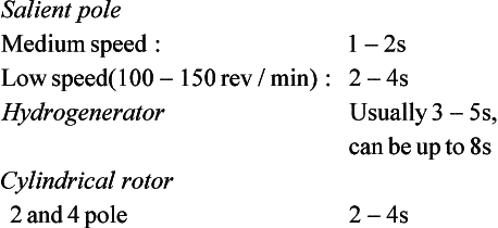
A directly coupled steam turbine may have 2–4 times as much inertia as its generator, but a hydraulic turbine adds relatively little. A hydrogenerator may therefore have to be larger than the electrical performance would require, whereas the turbogenerator designer can usually accept the inertia of the design that meets the other criteria.
28.7 Armature reaction
Balanced three-phase sinusoidal currents in the stator winding produce an approximately sinusoidal m.m.f. wave rotating round the airgap at synchronous speed ns = f/p rev/sec. The wave continuously changes shape between two extremes, which occur in turn every 1/12 of a cycle of the current. The wave can be represented as a fundamental plus harmonics thus:
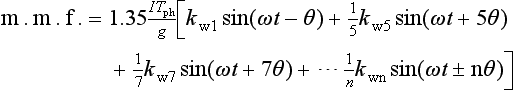
where 1.35((ITph)/g)kw1 ampere-turns per pole is the amplitude of the fundamental wave and θ is a space angle in electrical degrees (one fundamental pole pitch = 180°). Harmonic orders n are n = 6m ± 1 where m is any integer. The sign of n is opposite to that of 1 in n = 6m ± 1.
Each harmonic rotates at a speed inversely proportional to its order; the higher order of each pair, the (6m + 1), goes forwards (i.e. the same direction as the fundamental) and the lower one (6m − 1) goes backwards.
The harmonic fluxes induce small e.m.f.s at supply frequency in the stator winding, not large enough to affect the r.m.s. value of the phase voltage. However, they induce currents at 6m times supply frequency in the rotor damper winding, pole faces, etc. These can cause significant extra losses and local temperature rises.32,33 The fifth and seventh harmonic m.m.f.s are the largest, but with a 5/6 pitch winding, for which Kp5 = Kp7 = 0.259, and spread factors of about 0.2, they are reduced to about 1% of the fundamental m.m.f. The m.m.f. winding factors are the same as those applied to the calculation of open-circuit e.m.f.
Figure 28.6 shows how the gap flux wave shown in Figure 28.1(c) is distorted by armature reaction, and shows a small increase in the (mainly slot) harmonics. Harmonic currents supplied by the generator are not often troublesome, unless the load has large capacitance, or resonates to give a low impedance at a particular frequency. The harmonic content in the terminal voltage will depend on the impedances of the load and the generator at the harmonic frequencies.
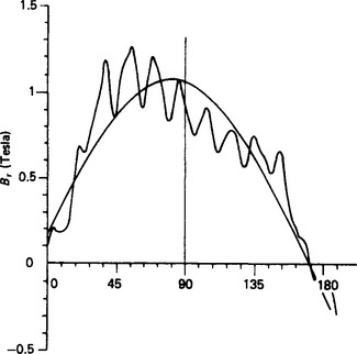
In fractional slot windings the currents produce also even harmonics and subharmonics: the latter have wavelengths that are multiples of the fundamental double pole pitch. In large multipolar machines such as large hydrogenerators, the subharmonic flux may cause unacceptable deflection and vibration of the stator core, especially if it is a bit shallow radially behind the slots, or has a natural frequency of vibration close to a subharmonic frequency. Some such stator frames have been damaged by this effect (see Liwschitz36,34 and Walker38)
28.7.1 Cylindrical-rotor machine
The gap flux wave developed by the fundamental stator (‘armature’) m.m.f. acting alone is nearly sinusoidally distributed because of the uniform airgap. The gap flux developed by the rotor (‘field’) m.m.f. acting alone has a trapezoidal distribution. On load the gap flux results from the stator and rotor m.m.f.s in combination. The fundamental components of the distributed m.m.f.s can be represented by phasors of peak values Fa and Ff ampere-turns per pole, respectively, each directed along the corresponding axis of maximum m.m.f. The fundamental component of gap flux on load is proportional to the phasor sum F of Fa and Ff (neglecting magnetic saturation).
Ff is centred on the pole axis (the direct or d axis) to which the interpolar axis (the quadrature or q axis) is in electrical space quadrature. In general, the axis of Fa is displaced from the d axis by an angle β depending on the load and the power factor. Fa can be resolved into components Fad and Faq, respectively, on the d and q axes. Figure 28.7(a) shows, for a balanced three-phase cylindrical-rotor machine, the stator and rotor current-sheet patterns for an instant of zero current in stator phase C. (The black areas represent outward, and the cross-hatched areas inward, current direction.) The m.m.f. phasors Fa and Ff are displaced by angle, β. The resultant m.m.f. acting on the airgap is the phasor sum Ff + Pa = F. Assuming each m.m.f. to develop an individual flux, the e.m.f.s Ef, Ea and Eph in Figure 28.7(b) are respectively induced by Ff, Fa and F. Then Fph is the terminal e.m.f. for a representative stator phase.
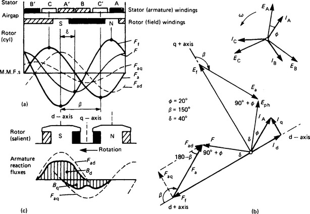
28.7.2 Salient-pole rotor machine
The gap reluctance is far from uniform, and a given stator m.m.f. acting on the q axis produces less flux than it would if acting on the lower reluctance of the d axis. This is indicated in Figure 28.7(c). The d axis flux is distributed almost sinusoidally, but the q axis flux contains significant space-harmonics, chiefly the third. To deduce the d and q axis fluxes, hence e.m.f.s and reactances, it is necessary to resolve Fa into the axis components Fad and Faq, then to evaluate separately the fluxes they produce. This is done in detail using, for example, finite element analysis of the field. Hand calculation can be done using coefficients presented by Wieseman44 and by Ginsberg et al.45 in terms of the pole and airgap profile, and the minimum gap reluctance at the pole centre line.
28.7.3 Magnitudes and equivalence of stator and rotor m.m.f
For a balanced three-phase winding with 60° phase spread, the peak of the fundamental component of the m.m.f. wave is
where I is the r.m.s. phase current, g is the number of parallel circuits per phase, Tph is the total number of turns per phase, and 2p is the number of poles. With a cylindrical rotor the proportions of the trapezoidal m.m.f. waveshape and the peak of its fundamental component depend on the field form factor Cf which is a function of the ratio
λ is usually 0.65 to 0.75, and Cf therefore from 1.06 to 1.0. Then the peak fundamental m.m.f. of the rotor is given by CfIfNf A-t/pole, where Nf turns per pole carry the field current If.
On load the rotor m.m.f. Ff must be such that when combined with the armature reaction m.m.f. Fa the net m.m.f. F must be sufficient to provide the flux needed to generate the e.m.f. E. Hence Fa must be put in terms of the rotor m.m.f. that would develop the same flux as Fa, i.e. equating the peak fundamental m.m.f.s of stator and rotor:
Putting Cf at a typical value of 1.03, the rotor equivalent of the reaction m.m.f. Fa is
With a salient pole rotor, with a distributed stator winding, a concentrated rotor winding, and a non-uniform gap reluctance, it is necessary in effect to calculate and equate the fundamental fluxes, not the m.m.f.s, along the direct axis.
Wieseman gives curves for estimating the factor Cdl, which is the ratio of the fundamental airgap flux produced by armature reaction m.m.f. directed along the direct axis to that which would be produced if the airgap were uniform and equal to the effective gap at the pole centre line. Then the peak fundamental flux density produced on the d axis by Fa is proportional to CdlFa. For typical profiles Cdl lies between 0.85 and 0.95.
The peak fundamental d axis flux produced by a rotor m.m.f. IfNf is proportional to C1IfNf. The value of IfNf that makes C1IfNf = CdlFa is Fat, the rotor m.m.f. equivalent of Fa. Then
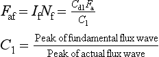
Putting in typical values of Cdl, and C1
Figure 28.20 shows how Fat is combined with Fe to calculate Ff, the on-load ampere-turns per pole.
28.8 Reactances and time constants11,83,84,86–91
In order to evaluate the steady-state behaviour of a synchronous generator or its response to changes of load, excitation and system disturbances, a mathematical model of the machine is required. Reactances have been defined which, with winding resistances where significant, can form an appropriate equivalent circuit for which behaviour equations can he written; these equations can then be solved to determine the performance of the machine.
The reactances commonly employed are described below. They are associated with a two-axis model, represented on the d axis by an equivalent stator winding, the field winding and a damper winding, and on the q axis by a second equivalent stator winding and one damper winding. Circuit impedances can normally be taken as reactances because the resistances are comparatively small; however, the resistance values directly influence the time constants.
Voltages, currents and reactances are usually expressed in per-unit (p.u.) terms of rated voltage and current; other values are put in p.u. by dividing actual voltage and current by the rated values. The unit reactance is the ratio rated phase voltage/rated phase current. Thus a reactance having a voltage drop of 0.2 p.u. when carrying 0.5 p.u. current has a value of 0.4 p.u. Stator voltages, currents and reactances are all per-phase values.
Each reactance is associated with a particular component of flux produced by either the d or the q axis component of current in the stator winding. A d axis current produces a d axis flux: as shown in Figure 28.7, the conductors in which it flows are near the q axis but they form coils magnetising on the d axis. Similarly a q axis current produces a q axis flux. The numerical value of each reactance is then the fundamental frequency e.m.f. per phase generated by the associated flux, divided by the corresponding component of current. Usually reactances are defined with rated current in the d or q axis and are termed ‘rated’ or ‘unsaturated’ values. With the heavy currents occurring under short-circuit conditions, saturation reduces the flux per ampere, and the saturated reactance values are lower.
The reactance values can be derived from the machine geometry by calculating first the permeance of the associated flux path and then the inductance L, i.e. the flux linkage with the stator winding per ampere of stator current in the required axis. The reactance (in ohms) is 2πfL. Difficulties arise in defining exactly the flux paths and permeances and in allowing for saturation at high flux densities, even though a large part of the leakage flux paths is in air.
28.8.1 Armature leakage reactance
The armature leakage reactance X1 results from stator leakage flux that crosses the stator slots, flux that passes circumferentially from tooth to tooth round the airgap without entering the rotor and flux linking the stator endwinding. X1 is a component of all the positive- and negative-sequence reactances. Since the flux paths are independent of the rotor, the reactance has the same value for both axes; and since the flux paths are the same for positive- and negative-sequence currents, X1 has the same value for both.
28.8.2 Magnetisation (armature reaction) reactances
The magnetisation (armature-reaction) reactances are associated with the synchronously rotating flux set up by positive-sequence current in the stator winding, i.e. by balanced phase currents. Suppose the field winding is rotating synchronously but is open-circuited, and a three-phase e.m.f. (V) of correct phase sequence is applied to the stator winding. After the initial damper circuit currents have delayed, a steady stator current I flows. If the e.m.f. is phased so that I produces flux along the pole axis, i.e. I = Id, then Id has a value sufficient to establish an airgap flux that induces a stator e.m.f. = V (neglecting the stator resistance and leakage reactance drops). V/Id is the direct axis magnetising reactance Xad. If the phasing is such that I produces only q axis flux, i.e. I = Iq, then V/lq is the corresponding reactance Xaq. In most generators, Xad lies between 1 and 2.2 p.u. In salient-pole machines, Xaq is typically 0.6 Xad. In cylindrical-rotor machines the airgap is of uniform length, but the rotor slots slightly increase the q axis reluctance, so Xaq is usually approximately 0.9 Xad.
28.8.3 Synchronous reactances
The synchronous reactances are the total reactances presented to the applied stator voltage when the rotor is running synchronously but unexcited:
The magnetising and synchronous reactances are steady-state values applicable with balanced phase currents of constant r.m.s. value. They are defined by considering the machine to be excited by stator current only. The two axis reactances can be represented by the equivalent circuits in Figure 28.8.
28.8.4 Transient and subtransient reactances
The transient and subtransient reactances relate to conditions that arise when the m.m.f. on the magnetic circuit of the machine is suddenly changed. Consider the conditions following the sudden application of a three-phase supply of voltage V to the stator winding, with the rotor running synchronously and its field winding closed but unexcited. The three-phase stator currents develop an m.m.f. that rotates synchronously with the rotor. (There are direct-current (d.c.) components as well, but they are not relevant here.) Suppose that the instant of switching is such that the stator m.m.f. is impressed on the pole axis. The flux linkages of the stator winding must induce an e.m.f. that balances V (neglecting resistance). If there were no current paths on the rotor, the stator would immediately carry currents necessary to magnetise the machine to the required flux level, i.e. I = V/Xd. However, if there are closed rotor circuits available (i.e. the field winding, damper windings and solid iron poleshoes), currents are induced in them, inhibiting the rise of flux through the rotor poles and so forcing the flux into rotor leakage paths of high reluctance. Hence the initial stator current must be larger than V/Xd. The leakage paths are largely circumferential in the pole faces, from pole to pole in the gap between adjacent salient poles, and across the wedges and tooth tips in a turbogenerator rotor. This path adds only a small permeance to that of the stator leakage paths alone, so the effective reactance is not much more than X1.
I2R losses in the damper circuits cause these currents to decay rapidly, enabling the flux to penetrate past the dampers into the pole and field winding region. The permeance of the available flux path therefore increases, decreasing the stator current needed to maintain the required stator flux linkage. Thus the induced rotor currents, and the stator current, decrease in unison, at first rapidly as the damper currents decay, then for a time more slowly, until eventually the induced current in the field winding has disappeared, the flux is fully established along the main flux paths and the stator current is settled at its magnetising value I = V/Xd. The main decay time is called the transient period, and the brief initial decay period is the subtransient.
The machine as seen from the supply system can be represented by the equivalent circuit shown in Figure 28.9(a), where Ikd and If are the components of Id needed to balance the induced damper and field currents respectively. The effective impedance increases progressively from its initial value of Xr in series with the other three circuits in parallel, through X1 in series with Xad and the field circuit in parallel when Ikd has reached zero, to X1 + Xad in the steady state. Thus the transient reactance ![]() and subtransient reactance
and subtransient reactance ![]() are
are
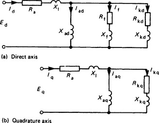
If the moment of switching is such that flux is established along the quadrature axis, similar arguments apply except that q axis flux has no net linkage with the field winding. There is, therefore, no q axis reactance corresponding to Xf on the d axis, and in this simple model the q axis circuit is as shown in Figure 28.9(b).
The q axis subtransient reactance is
In practice, the induced current paths in the iron on the d and q axes change as the flux distributions change, so neither axis can be accurately represented by a single damper circuit, with fixed X and R and therefore one fixed time constant. This is especially true of solid cylindrical rotors, in which the tooth tops and slot wedges form a surface damper cage of relatively high resistance with a time constant typically less than 50 ms. As surface currents decay, lower resistance current paths in the poles and beneath the slots become effective, introducing higher reactances with time constants up to a few seconds. Hence the machine can be represented more closely by having two damper windings on each axis. Traditionally the direct axis reactances X′d and X″d and associated time constants have been deduced from oscillograms of a sudden symmetrical three-phase short-circuit test, assuming only one damper circuit. Values appropriate to different levels of magnetic saturation can be found by testing at a number of voltages (tests at or near full voltage are rarely done because they cause very heavy forces on the windings). The short-circuit test measures only d axis values; other tests for these, and for q axis quantities, are given in IEEE Publication 115: 1983 and IEC Publication 34–4 1985; IEEE 115A 1987, describes frequency response tests (see Section 28.8.1).
In a salient pole rotor with laminated poles and specific damper cages, the damper circuits are more clearly defined, and a model with one damper on each axis (as well as the d axis field) is accurate enough for many purposes. Such a model has in the past been used for turbogenerators too, but advances in design and test procedures, and in computer analysis, have encouraged the use of the more elaborate models.
28.8.5 Negative-sequence reactance
Unbalanced load or fault conditions are usually analysed by the method of symmetrical positive, negative and zero phase-sequence components (p.p.s, n.p.s. and z.p.s. components). Currents of n.p.s. in the stator produce an m.m.f. rotating at synchronous speed in a direction opposite to that of the rotor. This m.m f. acts upon the d and q axes in turn, inducing double-frequency currents in any available rotor circuit. The stator presents a low reactance to n.p.s. current, taken to be the mean of the subtransient d and q axis values, i.e.
28.8.6 Zero-sequence reactance
Zero-sequence currents in the three phases are equal and in time phase, and their combined effect is to produce a stationary field alternating at supply frequency, therefore inducing a stator e.m.f. of that frequency. The m.m.f. and therefore the flux are small compared with the p.p.s. and n.p.s. components, and they depend heavily on the coil-span, falling from a maximum value to zero as the span decreases from full pitch to 2/3 pitch. Accordingly X0 is usually quite small.
28.8.7 Reactance values
Ranges of typical values of reactances and time-constants are given in Table 28.4. Since the ranges all depend on the details of the machine design, there will be exceptions to the following generalisations, which do however indicate normal trends.
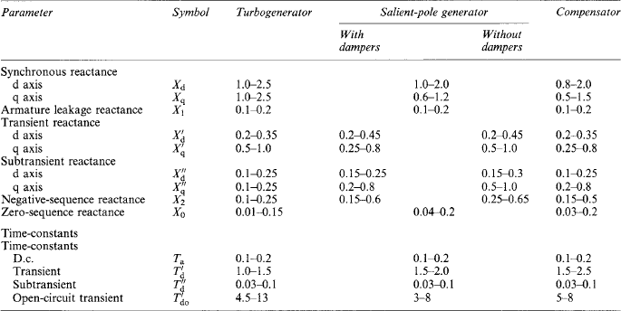
For a given output and speed, the physically smaller machine will have a higher current loading, so all reactances will be higher than those of a larger, and therefore ‘slacker’, design. At a given speed, reactances tend to rise with increasing rated output, since higher electrical loading and more intensive cooling are needed to attain more output per unit volume of active material. For a given output, low-speed machines are physically larger, and tend to have higher reactances, than high-speed designs.
28.8.8 Reactances and time constants
The reactances and time constants are based on equivalent circuits, such as those in Figure 28.9. Time constants are given by inductance/resistance ratios, i.e. the ratio of X/2πf to R. In the formulae below, 2πf is written as ω, the angular frequency. All time constants are in seconds if all X and R values are expressed consistently in per-unit or ohmic values.
28.8.8.1 Open-circuit
With the stator winding open-circuited, the leakage impedance (X1 and Ra) has no influence and the transient behaviour is determined by the inductance and resistance of the field winding. The open-circuit transient time constant is
The subtransient duration depends primarily on damper-circuit currents: if we neglect the effect of Rf, the time constant is
28.8.8.2 Short circuit
With the stator short circuited, current and flux changes are influenced by X1, but Ra is usually negligible. The transient time constant is
The subtransient short circuit time constant depends primarily on damper-circuit parameters:
The armature short circuit time constant relates to the rate of decay of d.c. components of stator current that occur from the beginning of a sudden short circuit:
28.8.9 Potier reactance
The Potier reactance Xp is an estimate of armature leakage reactance deduced from the open-circuit and zero-power factor (z.p.f.) curves; it is used in one method of calculating the on-load field current allowing for saturation. Xp is slightly higher than the true X1, especially for salient-pole machines where pole saturation is greater than on normal load because of the greater pole-to-pole leakage flux for the z.p.f. conditions. Hence using Xp somewhat overestimates the load excitation.
28.8.10 Frequency-response tests87–89
The d and q axis parameters can be measured by injecting one-phase current into the stator winding over a frequency range (typically 1 mHz to 1 kHz), the rotor being stationary with its d and q axes in turn aligned with the stator field. By fitting an expression in the Laplace form
to the curve of d axis reactance against frequency, Xd and the time constants can be found, and the corresponding X′d and X″d values derived, appropriate to a machine model with one damper circuit on the d axis.
To fit the q axis reactance-frequency curve reasonably closely, it is necessary to assume two damper circuits, which give an expression similar to the d axis expression quoted, but with q axis quantities. Thus X′q and T′q values are deduced, as well as X″q and T″q despite the absence of a field winding on the q axis.
More accurate fits to the measured frequency-response curves may be obtained by using an equivalent with more damper circuits and corresponding time-constants. Techniques have been developed for taking frequency-response curves on the machine in service in order to obtain values more appropriate to the load condition. There is an extensive literature in the IEEE Journal (Power Apparatus and Systems). A review of the subject, and some specific papers are contained in IEEE Publication 83TH0101-6-PWR, Symposium on Synchronous Machine Modelling for Power System Studies, February 1983.
ANSI/IEEE 115A—1995 describes ‘Standard procedures for obtaining synchronous machine parameters by standstill frequency response testing’. It contains eight references, and an appendix showing how operational impedances transfer functions and the R and L values of the equivalent circuit can be deduced from the measurements.
Measurements of the behaviour of machines and systems when they are subjected to test disturbances have shown that for some stability calculations the simpler circuits, even with the subtransient effects neglected, are adequate. However, for calculating short-circuit torques, the sub-transients must be included; and for detailed analysis of the effects of excitation control, more elaborate models are needed.
28.9 Steady-state operation
28.9.1 Open- and short-circuit characteristics
Prediction of the operation of a generator in the steady state is based on the open- and short-circuit characteristics shown in Figure 28.10.
With the stator winding on open circuit, the field current If produces a mutual flux linking the stator and rotor windings, plus a relatively small rotor leakage flux linking the rotor winding only. The corresponding stator winding flux linkage per phase ψ0 generates the stator e.m.f. At rated speed, the value of If represented by 0b generates rated e.m.f. Eo represented by bg; 0a is the current needed to overcome the reluctance of the airgap, and ab is required for the iron parts of the magnetic circuit.
With the stator winding short circuited, field current 0d circulates rated stator current Isc, represented by hd. Armature-reaction m.m.f. produced by Isc is wholly demagnetising, and the difference between it and the field m.m.f. (0d) develops a mutual flux Φsc, sufficient to induce an e.m.f. Esc equal to the stator leakage reactance drop IscX1. This neglects the stator winding resistance Ra and any harmonic fluxes developed by the stator and rotor m.m.f.s.
The flux Φsc is too small to cause magnetic saturation; hence Isc is proportional to If. As both Esc and X1 are proportional to frequency, the short-circuit characteristic is almost independent of speed; nevertheless, it is usual to obtain it at rated speed.
Still neglecting saturation and armature resistance, a field current If = 0a gives Eo = af on open circuit and Isc = ak on short circuit. Thus on short circuit the stator appears to present a reactance Xdu = Ea/Isc = af/ak, a constant representing the unsaturated d axis synchronous reactance Xad + X1 · Xdu is usually defined in terms of If as the ratio 0d/0a in Figure 28.10. The short-circuit ratio is defined as 0b/0d which from the geometry is (0b/0a)(1/Xdu). Here 0b/0a is a saturation factor, usually in the range 1.1–1.2.
28.9.2 Phasor diagram and power output
The resultant m.m.f. of the stator current I and the held current If develops an airgap flux Φ which induces the stator phase e.m.f. Eph. The stator leakage flux Φ1 induces the e.m.f. E1.
Detailed analysis allowing for local flux distribution and the variation of magnetic permeability in ferromagnetic parts of the magnetic circuit is necessary in design. However, the performance of a generator on load and under fault conditions can be examined conveniently (and, for many purposes, adequately) by combining the e.m.f.s considered to be produced by If alone and I alone, taken separately. Neglecting saturation, the machine can be represented by an equivalent circuit of constant reactances, and with e.m.f.s proportional to their respective currents. Usually the effect of stator-winding resistance can be neglected. Further, by assuming the airgap flux distribution to be sinusoidal, phasor diagrams can be employed. Finally, for a cylindrical-rotor machine the uniform gap length makes it permissible to assume that the d and q axes have equal reluctances. In practice, Xq is usually 0.85Xd to 0.95Xd.
Adopting the conventions of IEC Publication 34–10, the basis is generator action, with power positive when it flows from generator to load. An induced e.m.f. is e = −dψ/dt, where ψ is the linkage between flux and stator winding. This means that the e.m.f. phasor lags the flux (or linkage) phasor by 90° electrical. Then, since the flux linking a stator phase winding is in time phase with the current, the phasor diagram in Figure 28.11 applies for a generator on inductive load, and Figure 28.12 shows the corresponding equivalent circuit. Here ψf is the stator linkage produced by the field current Ir alone; it would induce on open circuit the e.m.f. Ef. The load current I produces the linkage ψa (the armature-reaction effect) reducing Ef to the airgap e.m.f. Eg. Stator leakage flux produces the linkage ψ and the e.m.f. E1, and the total induced e.m.f. is E. Subtraction of the volt drop IRa gives the terminal voltage V. With the convention that the inductive voltage drop leads the current by 90°, the two equivalent equations in phasor terms are
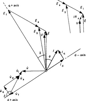
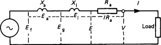
If, as is usually permissible, Ra is neglected, then V and E coincide, simplifying the diagram to that in Figure 28.13. Here ab on a voltage scale represents IXd. If the scale is divided by Xd then ab represents I. The angle abc is φ, the power-factor angle; bc represents the active-power component of I; but bc is also Ef sin δ, and hence the power per phase is (VEf/Xd) sin δ.
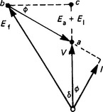
At no load, V and Ef coincide. Hence δ is the power (or load) angle, i.e. the angle by which the rotor must be driven forward relative to the resultant flux (i.e. forward from its no-load position) to deliver active power. If V and Ef are fixed, then the active-power output P is proportional to sin δ, reaching a maximum for δ = 90°.
For a salient-pole machine, account must be taken of the differing d and q axis reluctances. The q axis component current Iq has a lower flux-producing effect than in a cylindrical-rotor machine, i.e. Xq is smaller than Xd. Figure 28.14 shows the phasor diagram for an output at lagging power factor, with ψ1 regarded as part of ψa and E1 as part of IXd. The position of the q axis and the length 0e = Ef are found by dividing ab at c such that ab/ac = Xd/Xq. The voltage triangle abd is similar to the current triangle I, Id, Iq, each side being the appropriate current multiplied by Xd. As ac/ab = de/db = Xq/Xd, it follows that de = IqXq, whence
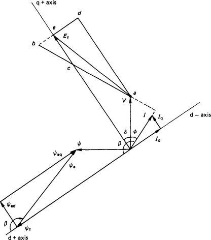
The triangle ade is similar to the flux linkage triangle ψad ψaq ψq.
Again δ is the load angle. It is less than that for a cylindrical-rotor machine of the same Xd delivering the same active power at the same voltage and excitation. From the geometry of the phasor diagram it can be shown that the active power output is
The second term is the power that is available with zero field excitation (Ef = 0) and which is developed as a reluctance torque and power that depend on the different axis reluctances Xd and Xq. Figure 28.15 shows power—angle curves for a salient-pole machine with typical values of Xd and Xq and for different excitation levels. In a cylindrical-rotor machine Xq is approximately 0.9 Xd, so the reluctance torque (Ef = 0) is small, and the power—angle curve is not far from sinusoidal.
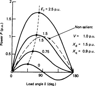
28.10 Synchronising
Almost all a.c. generators operate in parallel with others. This raises the problem of switching a machine safely into service (‘synchronising’) and ensuring that it subsequently remains in synchronism. It is here assumed that a generator is to be connected to a system large enough to fix its voltage and frequency regardless of changes in load and excitation on an individual generator.
28.10.1 Synchronising procedure
The following conditions must be satisfied by the incoming machine with respect to the network bus-bars: (I) the speed must be such that its frequency is close to that of the bus-bars (preferably about 0.2% high); (2) its r.m.s. voltage should equal the bus-bar voltage within ±5% and (3) the machine and bus-bar voltages must be momentarily in phase, or within ±5° of phase coincidence.
In manual synchronising, condition (3) involves the use of a synchroscope to indicate to the operator the relative phase positions. Allowance must be made by the operator for the 0.2–0.4 s time-lag between initiation of switch closure and the actual closure of the switch contacts.
Alternatively, the process may be carried out by automatic means which monitor the conditions and initiate switch closure at the proper instant.
28.10.2 Synchronising power and torque
If a generator running in parallel with others is disturbed from its steady state, for example by a small change in system voltage, the electromagnetic torque no longer balances the driving torque (presumed constant), and the rotor swings from load angle δ1 to a new angle δ2 at which the balance is restored. The equal-area graphical criterion for stability is useful to give a picture of the oscillation process with a single machine,172,173 but is inadequate for accurate calculation. In Figure 28.16 the initial operating point a moves to b as the terminal voltage drops from V1 to V2, reducing the electrical output. The rotor oscillates between δ1 and δ3 before settling at δ2, again delivering output Pel equal to the mechanical power input. Areas abc and cde represent the energy interchanged between rotor kinetic energy and electrical energy.
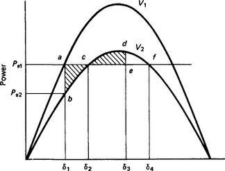
If Pel is too close to the peak of the V2 power curve, area cdf is less than abc, so the rotor can never be slowed to synchronous speed on its forward swing. It rises to a mean speed a little above synchronous, say up to 1%, delivering rather less than the initial load as an induction generator. As the rotor poles slip past the stator m.m.f. wave the speed fluctuates, and there are large swings in current, power, reactive and voltage. An e.m.f. at slip frequency is induced into the field winding, and may reach four or five times the excitation voltage needed at rated load. This forms one of the design criteria for the diodes or thyristors of the excitation system. In a turbine-generator, increased leakage flux in the end regions causes rapid heating of the core ends. E.m.f.s induced between the laminations have in a few machines initiated local damage to the core-plate insulation, and serious core faults have developed in subsequent service. Many machines have pole-slip protection to trip the machine if synchronous running is not restored very quickly.
If Δδ is a small deviation from δ2, the accelerating, or retarding, torque ΔT is approximately Δδ (slope of the T−δ curve at δ2) = ΔδTs where Ts is the synchronising torque coefficient. The corresponding synchronising power ΔP = ωmΔT = ΔδPs where ωm is the synchronous speed (in mechanical rad/s = 2π rev/s) and Ps is the synchronising coefficient.
If the rotor swing were very slow the appropriate P−δ curve would be the steady-state curve such as in Figure 28.15 and
where Ps, the total for three phases, is in watts/electrical radian if V and Ef are line voltages (not phase) and reactances are in ohms/phase. Ts is then in newton-metres/electrical radian. Usually per unit (p.u.) values are more convenient, using rated apparent power and phase voltage and current as bases. Then Ps is in p.u. power/electrical radian, and Ts p.u. is numerically the same.
28.10.3 Rotor oscillation
The synchronising torque acting on the inertia of the coupled rotors constitutes an oscillatory system with a natural frequency
where ωs = 2πfs = 314 for fs = 50 Hz and 377 for 60 Hz.
This formula ignores the effect on the frequency of the damping torques and, more significantly, the additional synchronising torques developed by currents induced in damper cages and solid iron.
In practice too, the natural frequency for almost any machine and system lies in the range 1–3 Hz, within which the time of a half-cycle of oscillation is comparable with, or less than, the transient time constant. The field flux linkages do not have time to change significantly, and the effective reactances are the transient, not the synchronous, ones.
With this assumption a round-rotor machine can be represented simply as a constant e.m.f. E′ behind the transient reactance X′d. E′ is determined by conditions before oscillation starts, and is assumed not to change as δ′, the angle between E′ and the terminal voltage V, changes.
Then the peak of the transient power curve is
The synchronising power coefficient
Calculations from the steady-state and transient representations are compared in Table 28.5 for a generator set with Xd = 1.5, ![]() = 0.25 and H = 8 s, with an initial load of 1.0 p.u. at 0.95 p.f. leading.
= 0.25 and H = 8 s, with an initial load of 1.0 p.u. at 0.95 p.f. leading.
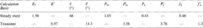
In many investigations this approximate model may be good enough, at least as a starting point. For large swings, and to get more accurate results, an appropriate equivalent circuit representation is needed. The damping and induction torques can be included, as also can the influence of fast-acting excitation systems. Computer solution of the resulting equations is necessary. The effect of series reactance Xe between the machine and the fixed voltage bus is to reduce the synchronising torque and lower fn. Xe is allowed for by adding it to the machine reactances.
28.11 Operating charts
Operating charts based on Figure 28.11 or 28.14 define the operating limits imposed by the prime mover, excitation, load and stability. Saturation is ignored and the reactances are deemed constant.
28.11.1 Cylindrical-rotor generator
In Figure 28.17, 0ab is the synchronous reactance triangle. The fixed phase voltage V is represented by 0a to a scale of say v V/cm. Point b represents rated load, where ab is the rated stator current to a scale of v/X d A/cm, at the power factor cos dab. ad and ag are the active and reactive components of ab.
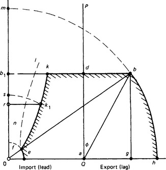
0b represents Ef, the phase e.m.f. behind Xd. The corresponding value of If can be read off the airgap line of the open-circuit characteristic shown in Figure 28.10; the value of If is not seriously inaccurate at leading power factors where magnetic saturation is low.
To a scale of (3 Vv)/Xd V-A/cm, ab represents rated apparent power, ad the active power, and ag the reactive power.
a0 represents, at v/Xd A/cm, the magnetising current V/Xd drawn from the system at no load if If is reduced to zero, and also the corresponding vars V2/Xd at the scale (3 Vv)/Xd V-A/cm.
The P and Q axes are usually marked in megawatts and reactive megavolt-amperes, respectively, or in p.u. terms where, if V = 1 p.u., ab = rated apparent power = 1 p.u., ad = active power, cos φ p.u. ag = reactive volt-amperes, sin φ P-u. and a0 = rated MVA/Xd = (1/Xd) p.u.
Operation must be so controlled that the operating point is within the boundary set by (i) an arc of centre a and radius ab representing rated stator current, (ii) an arc bh of centre 0 representing rated field current, and (iii) the line bdb1 representing the rated active power output of the prime mover.
The line 0m, corresponding to a load angle δ = 90°, shows the theoretical maximum power (since the output falls for δ = 90°), while 0b1 is the lowest field current for which rated power can be delivered, the corresponding stator current then being ab1.
Instability at all loads occurs when the generator (being underexcited) absorbs the reactive power 0a of value 1/Xd p.u. The line 0a to the current scale is the zero-power-factor component of stator current; considered as delivered to the power system, 0a leads the terminal voltage V.
Stable operation in practice is not possible up to the theoretical steady-state limit line 0m. It is usual to construct a practical stability line such as 0fk on which, from each point such as k1, operation for a given excitation 0s = 0k1 is not permissible in the region rk1. The load increment rs may be a fixed fraction of rated load or may change progressively between no load and full load. Often, a minimum acceptable field current is defined to avoid pole-slip at low load when a system voltage drop occurs (for the synchronising torque depends on VIf). The minimum excitation is typically 20% of that needed on no load giving the limiting arc ef.
With a constant active-power output, the stator leakage flux in end-winding spaces increases as the power factor becomes more leading. This increases the loss, and the temperature in the end core packets and clamping plates will rise. Hence an end-heating limit line In may be specified. Either the practical stability or the end-of-core temperature may set the limit on the reactive power that can be absorbed.
The operating chart can form the dial of a P−Q meter having a pointer moving parallel to each axis. Where the pointers cross indicates the load point, and the margins between the output and the several limits are readily observed.
The effect of reactance Xe (of, say, a transformer or power line) between the generator and the fixed-voltage bus-bar is allowed for by adding Xe to Xd and Xq. Then for a cylindrical rotor machine the steady-state stability limit is reached where δB = 90°: the reactive power QL is VB2/(Xd + Xe) and the maximum real power PL is VBEf/(Xd + Xe). At any stable load condition
The phasor diagram in Figure 28.18(b) shows that the presence of Xe requires the generator to operate over a range of terminal voltage. Generators are usually designed to deliver rated megavolt-amperes at rated power factor over a voltage range of ±5%, and a frequency range of ±2% or so. As VT and f move away from the rated (1 p.u.) values, the rotor or stator temperature rises will increase. If VT or f goes outside the design range, load may have to be reduced to avoid unacceptably high temperatures. See, for example, IEC 34–3 (Section 28.21).
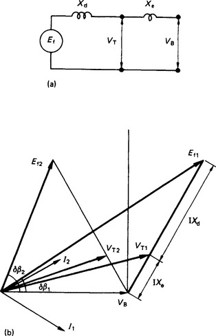
To provide a voltage range of, say, 10% rather than 5% adds significantly to the size and cost of a large machine. In service the p.u. reactances increase as the voltage decreases, and this reduces the stability margin. Hence many generator transformers have on-load tap-changers, to reduce the range of generator voltage needed.
28.11.2 Salient-pole generator
From the phasor diagram the P−Q chart for operation at fixed VT of 1 p.u. can be drawn as in Figure 28.19; ab, ad and ag are the stator current or volt-ampere quantities, as before; ac/ab = Xq/Xd; a0 = 1/Xd; as = 1/Xq; be ⊥ oe; slb||oe; and lb = oe. Hence ols = 90°, and the semi-circle constructed on diameter 0s represents a zero-excitation boundary. Angle bs0 = e0a = the load angle δ. At any load, Ef and If are represented by a length such as lb, on the line through s. (For any constant Ef and If, the locus of b is not quite a circular arc, but this becomes evident only with low excitations near the stability limit.)
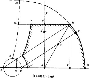
ad1 is the power contributed by Ef, and dId = In is the reluctance power derived from the difference between Xd and Xq.
The theoretical steady-state stability limit is the line skb1m. One method of finding the line is to use the expression dP/dδ = VEf cos δ/Xd + V2(Xd − Xq) cos 2δ/XdXq to find consistent values of Ef and δ that make dP/dδ = 0 (or see reference 8, article 6.5). A practical limit such as ptf can be constructed as for the round rotor generator, but with modern excitation controllers operation even beyond the theoretical limit, or with negative excitation, may be accepted, at least as a temporary condition.
With external reactance Xe, the intercepts of the zero-excitation circle lie at a0 = 1/(Xd + Xc), and as = 1/(Xq + Xc). For a given Ef the peak power at the stability limit is also reduced.