
28.12 On-load excitation
Use of the constant unsaturated value of Xd leads to values of Ef higher than those that occur for a practical machine. Thus a cylindrical-rotor generator with Xdu = 2 p.u. and carrying rated load at p.f. 0.85 lagging would have Ef = 2.67 p.u. while a practical machine would saturate at around 1.5 p.u. If It were read from the airgap line for Ef = 2.67 p.u. it would be about 15% low. At leading power factor, for which saturation levels are low, the error would be small. However, a more accurate estimate of the field current If is needed in the design of the excitation system and its cooling, and to determine the open-circuit e.m.f. that would be reached if the automatic voltage regulator failed to limit the excitation on sudden load rejection.
Flux distributions can now be calculated in considerable detail using computer programs that contain information on the geometry of the magnetic circuit, m.m.f.s of stator and rotor currents and values of iron permeabilities appropriate to the local flux densities. Hence, open-circuit curves and excitation on load can be calculated without much labour from design data once a program has been proved. However, methods based on phasor diagrams and adjusted reactances, making separate allowance for saturation, are still of value if a suitable program or the detailed design information, is not available. They are also needed when calculating excitation from test results on built machines.
Such methods add the rotor m.m.f. phasor needed to generate the no-load voltage to that needed to balance armature reaction. They differ in the choice of the voltage and in the way allowance is made for the effects of saturation.
The open-circuit short-circuit and zero-power-factor characteristics (o.c.c., s.c.c. and z.p.f.c.) are required, either by test or from design calculations. All the methods should give the full-load excitation to within ±5%, or closer at leading power factor. We consider three methods here.
28.12.1 M.m.f. phasor diagram (Figure 28.20)
The e.m.f. E behind the leakage reactance X1 requires a field m.m.f. Fc, read from the calculated or tested o.c.c. Far is the armature-reaction m.m.f. in rotor terms, obtained by using the equations in Section 28.7 or (if X1 is known) by calculation from the tested s.c.c. as follows. To circulate stator current I on short circuit, excitation In is needed; to generate an e.m.f. to balance IX1 drop, If2 is needed; hence the armature-reaction m.m.f. is Faf = If1 − If2. Ef is the excitation m.m.f. required for the load current I at terminal voltage V and p.f. angle φ. Figure 28.20(c) shows the diagram for a salient-pole machine with a leading p.f. load. As in Figure 28.14, ab is divided at c such that ac/ab = Xq/Xd to find point f.
28.12.2 The ANSI Potier reactance method (Figure 28.21)
ANSI Potier reactance method (ANSI/IEEE Publication 115, Section 4) requires the tested o.c. and z.p.f. characteristics, and is limited to machines that can be loaded for a z.p.f. test. In Figure 28.21(a), A is the rated-current short-circuit point and D is the rated-current rated-voltage point: to reach D the field current exceeds the rated-load excitation level. Draw DC = A0, and draw CF parallel to the airgap line 0BH. Drop FL perpendicular to DC, and draw triangle 0BAM similar to CFDL. Then FL is the Potier voltage drop IXP, and DL is the armature-reaction m.m.f.
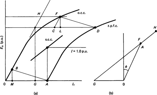
The argument is that for a given stator current the armature-reaction and leakage-reactance voltage drops are constant, but the latter requires more excitation at the higher levels of saturation.
0G, 0A and FH in Figure 28.20(b) are excitation currents as in (a), with 0G for rated voltage on the airgap line. GH is the total excitation required.
The z.p.f. test may have to be performed at less than rated stator current; the z.p.f.c. is then closer to the o.c.c., and DL and FL are smaller. Nevertheless, the Potier reactance is still considered to be Xp = FL/I up to rated value.
Given only the o.c.c. and s.c.c., and no facility for adequately loading the machine, one procedure is to measure the d axis subtransient reactance from a sudden-short-circuit test (or by the IEEE method below) and to use it as Xp.
The test method for X″d in ANSI/IEEE 115, Clause 7.30.25, is to apply a voltage E of normal frequency to each pair of stator terminals in turn and to observe the current I with the rotor stationary. Let the three quotients of E/I be A, B and C. Then with E and I in per-unit values of rated phase voltage and current, X″d = (A + B + C)/6 to an approximation. To avoid rotor overheating, the duration of the test should not exceed the maker’s recommendations (e.g. 0.2 p.u. for a time sufficient to read the meters).
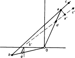
28.12.3 Use of design calculation (Figure 28.22)
Methods can be refined by allowing for the rotor pole-to-pole leakage. From a knowledge of the airgap flux, the m.m.f.s required for the gap, stator teeth and stator core are calculated. The m.m.f. for the rotor pole and body are calculated from the gap flux and pole leakage. The component phasors are added as in the diagram, where the total rotor m.m.f. per pole bc is obtained from 0a (armature-reaction), Ob (gap, teeth and core) and ac (pole and body). Saliency can be allowed for by dividing 0a at d such that 0d/0a = Xq/Xd. Then the total rotor m.m.f. is bc′. This differs very little from bc, but the load angle δ is more accurate.
28.13 Sudden three-phase short circuit6,7,11,19
If a three-phase generator is initially excited to a phase e.m.f. Eo on open circuit, and then the three phases are suddenly short circuited together, the stator winding carries balanced three-phase currents of up to several times full-load value depending on the magnitude of Eo. These currents produce a m.m.f. that rotates synchronously with the rotor, with its axis along the main pole axis, tending to reduce the mutual flux from its initial value. Change of flux linkage in a closed circuit induces therein a current opposing the change. Hence large direct currents are induced in the rotor damper circuits and field winding.
The combined effect of the large and opposing stator and rotor currents is to produce large leakage fluxes around the stator winding, the damper circuits and the field winding while the mutual flux along the main flux axis decreases correspondingly, so that the total flux linkage with each winding remains momentarily unchanged. I2R losses rapidly dissipate stored magnetic energy and the damper currents rapidly decay. Typically, the induced field current reaches its peak a period or two after the short-circuit instant and then decays relatively slowly (Figure 28.23).
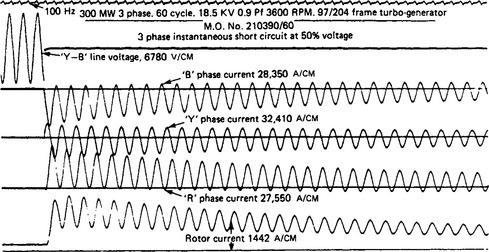
In the stator, each phase current is asymmetric to an extent depending on how near the phase voltage was to zero at the instant of short circuit; zero instantaneous voltage produces full asymmetry. Thus each phase carries a d.c. component which, at the instant of short circuit, is equal and opposite to the instantaneous a.c. component. These d.c. components produce a stationary m.m.f. sufficient to hold the stator flux linkage momentarily unchanged, i.e. fixed relative to the stator in the position the stator flux linkage occupied at the short-circuit instant. The d.c. rapidly decays, and with it the stationary field; while it persists, however, the rotation of the rotor within it induces rotational-frequency currents in the rotor damper and field circuits. The a.c. in the field is clearly seen in Figure 28.23; it is the greater, the less effective the damper circuits are. With no damper at all, the induced d.c. and the zero-to-peak amplitude of the a.c. would initially be equal.
The path taken in the rotor by the stationary airgap flux has a greater permeance when the d axis coincides with the stationary flux axis than when the q axis coincides. Hence the flux fluctuates at twice fundamental frequency, and double-frequency current is induced in the stator winding. This current and the a.c. in the rotor decay as the stator d.c. component decays. The magnitude of the second-harmonic stator current depends on the difference between X″d and X″q it is small in turbogenerators and in salient-pole machines with good interconnected damper windings.
In summary, the a.c. components in the stator give rise to the d.c. components in the rotor circuits; after the subtransient period, stator a.c. and field d.c. decay together with the transient short-circuit time constant, T′d. The stator d.c. components produce the rotor a.c, and these decay together with the armature short-circuit time constant Ta.
Direct-axis reactances and time constants are derived from the oscillograms of a three-phase short circuit as follows (see Figure 28.24 and Section 28.22: BS EN 60034–4:1995 and ANSI/IEEE Std 115–1995). The oscillograms should record for not less than 0.5 s; Id can be measured by instruments or by taking a second oscillogram after the steady state has been reached. Speed and field current should be constant throughout. E0 is the open circuit phase e.m.f. corresponding to the rotor excitation.
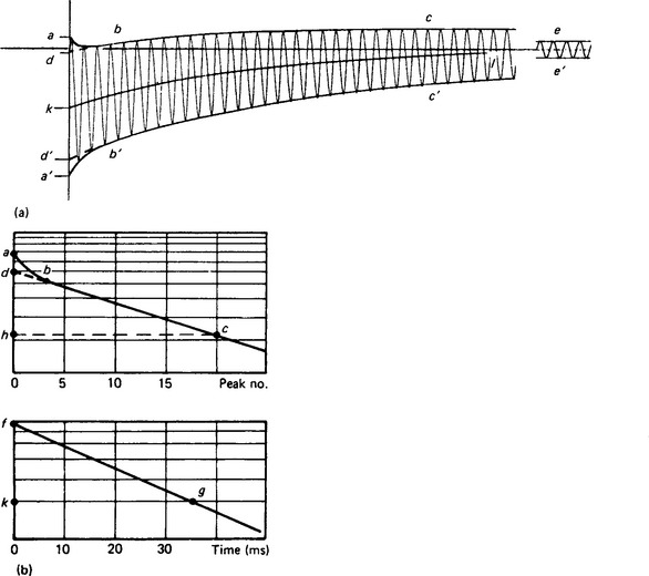
Figure 28.24 Analysis of a short-circuit current oscillogram: (a) current envelope; (b) logarithmic plot
The modern testing technique includes also digitally recording voltages and currents, and using computer programs to analyse the results and to present values of reactances and time constants. The principles are the same as for the analysis of the oscillograms described below.
(1) Draw the envelopes abc and a′b′c′ of one phase-current oscillogram. Then aa′ is the double-amplitude of the prospective current at the instant t = 0 of short circuit. (The first current peak is slightly less than 1/2 aa′ because of the rapid subtransient decrement.) Taking aa′ as scaled in per-unit terms, the r.m.s. current is ![]() and
and
(2) Project the envelopes in the transient region, cb and c′b′, back respectively to d and d′, ignoring the initial rapid subtransient decrement (this cannot be done with great accuracy). Then ![]() and
and ![]() .
.
(3) Repeat steps (1) and (2) for the other two phases and derive the mean values of ![]() and
and ![]() .
.
(4) For a closer estimate, the equation relating the r.m.s. value of the a.c. short-circuit current I1 to time may be used:
where Id = ee′/![]() is the sustained steady-state short-circuit current, and
is the sustained steady-state short-circuit current, and ![]() and
and ![]() are the transient and subtransient r.m s. currents respectively, corresponding to dd′ and aa′, respectively, at t = 0.
are the transient and subtransient r.m s. currents respectively, corresponding to dd′ and aa′, respectively, at t = 0.
(5) Measure (e.g. in centimetres) the double-amplitude between the envelopes at each current peak and subtract ee′ from each. Plot the results as ordinates on a logarithmic scale, to a linear base of time. This gives the curve abc in Figure 28.24(b).
(6) Project cb by a straight line to d at t = 0. Then
[d (cm)/![]() ] × current scale of oscillogram
] × current scale of oscillogram ![]() whence
whence
[If bc is not linear, the decay is not exponential and ![]() is not a constant. I′d and T′d can be estimated from a straight line drawn through chosen points on the curve bc where the transient current components are b and 0.368b (see IEC 34–4: 1985).]
is not a constant. I′d and T′d can be estimated from a straight line drawn through chosen points on the curve bc where the transient current components are b and 0.368b (see IEC 34–4: 1985).]
(7) The subtransient r.m.s. current at t = 0 is I′′d = I′d + the rapidly decaying component represented by da. Thus
The intercepts between ab and db are drawn to extended current and time scales in the lower part of Figure 28.24(b). Point f on the ordinate scale corresponds to da.
(8) Time constants are obtained from the slopes of the current—time plots. At c on line dc the transient component at time t is represented by h on the logarithmic ordinate (centimetre) scale and by hc on the time scale. It is related to I′d at t = 0 by
where hc is in seconds and d and h are in centimetres. T′′d is obtained similarly from the extended-scale plot in Figure 28.24(b). The ![]() .
.
(9) The procedure (5)–(8) is repeated for the other two phases and the mean values are obtained.
(10) The reactance values decrease with increasing short-circuit current (and therefore with increasing open-circuit voltage Eo). Rated-current values are obtained when at t = 0 the transient current I′d is equal to rated current. A range of short-circuit tests spanning the expected X′d will give a plot of reactance to a base of transient current I′d from which the appropriate value can be found. A rated-voltage value, if required, is obtained by testing at 1 p.u. voltage for a small machine without a transformer, but the electromechanical forces on the stator endwindings would be excessive in a large generator. Tests up to 0.7 p.u. voltage simulate a fault on the h.v. side of the transformer in a generator—transformer unit and are more relevant to the service conditions of a large machine.
(11) The armature short-circuit time-constant Ta is determined from the decay of the d.c. components of stator current or from the decay of the a.c. component of induced field current. The latter method is simple: it requires only a log-linear plot of the a.c. component to a base of time, similar to the plot in Figure 28.24(b). The stator d.c. component is represented by the median line kl of the current envelopes in Figure 28.24(a). However, if there are significant even-order harmonics then the median is displaced and a waveform analysis is necessary to find the harmonic effect. This will occur in a salient pole machine that has no effective damper winding, and so is not common.
28.14 Excitation systems
A synchronous machine requires an excitation system to provide the field current for magnetising the machine to the desired voltage and, when it is running in parallel with others, determining the lagging reactive power generated or received. It is customary for each generator to have its own self-contained excitation system, which provides the power required to supply the I2R loss in the field circuit. This varies between about 10 kW/MVA for small machines and 5 kW7 MVA for very large units.
Excitation voltage and currents are chosen: (i) to give field winding conductors that are mechanically robust in small machines and not too massive in large ones, (ii) to suit the ratings of available diodes or thyristors, and (iii) to give convenient designs of exciter, and also of slip-rings where these are used. Values range from a few score amperes and volts on very small machines up to say 8 kA at 600 V on the largest turbogenerators. At no load or with leading power factor, control of the exciting current is needed down to about one-third of the value for rated load.
The excitation system must respond to applied signals quickly enough to have the desired effect on the generator flux. Its duties can be broadly classified as:
(1) to control the generator voltage accurately as slow changes of power and reactive loading occur;
(2) to limit the fluctuations of voltage when loads are suddenly imposed or removed;
(See references 168, 172 and 173.) These duties require different characteristics of the excitation system: these must be reconciled to provide proper control.
The performance of an excitation system is represented by its response ratio, or its response time and ceiling voltage. BS EN 60034–1:1998 gives definitions, and ANSI/IEEE Standard 421.1 gives definitions and methods of test for these and for other characteristics. In Figure 28.25, abdm is the voltage—time curve obtained, starting from the voltage Ve needed on the generator field winding at rated load, when the control is suddenly changed to cause ceiling voltage Vc to be reached as quickly as possible. Definitions are, where area abdf equals area agf:
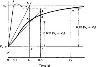
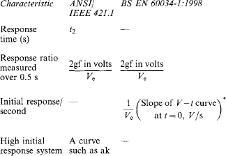
*The initial response is (Vc- Ve)/(t1Ve) per second if curve abd is exponential.
The measurements are conveniently made with the exciter on open circuit, but for analysing the generator behaviour values are needed with the exciter supplying the rotor winding. Where such testing is impractical, the on-load values must be calculated using known parameters of the machine(s).
Any system with a response time of 0.1 s or less is called a ‘high initial response system’. A thyristor system166,171 supplied from a transformer (or from an exciter machine that runs continuously at ceiling voltage) is inherently a high initial response system. A brushless exciter system165,167 can be given high initial response by forcing the exciter field current with a pilot exciter voltage that may be 5–10 times that needed for rated generator output. The exciter field must be designed to have a short time constant; the whole magnetic circuit must be laminated, and damper windings, both deliberate and incidental, must be avoided. For example, clamping bolts and plates should not form closed loops linking flux. The exciter output voltage can be forced to a ceiling value of, say, 2–3 times Ve in less than 0.1 s. The output current rises more slowly, depending on the effective time constant of the generator field circuit. The controller may limit the exciter field current to say 2 1/2 times the rated load value. In service such forcing would usually occur only for a few periods of up to about 0.5 s each as the rotor swings and returns to synchronism after a system fault.
A heavily forced main exciter with Vc about 2Ve may provide the required initial response more cheaply than would a bigger exciter with yet higher Vc but a longer time constant.
Whatever the performance of the excitation system, the change in generator flux is delayed by eddy currents induced in its field winding and any available damper circuits. It is not practicable to constrain the design to avoid these: for mechanical reasons a turbogenerator needs a solid forged rotor (except very small ones), whilst a hydrogenerator with laminated poles needs pole-face dampers. Hence the natural generator time constants have to be accepted, and the excitation system designed to suit them. The extra cost of excitation systems to achieve more and more rapid response may become unjustifiably great in relation to the control actually achieved on the generator.
For the duties (1) to (4) listed above, the characteristics of the excitation system need to be as follows.
(1) To hold the generator voltage within specified limits, which may be between ±3%, and ±0.5% of the set voltage, the excitation system needs a high d.c. gain, but a moderate ceiling voltage is enough to supply the small and slow changes of excitation needed.
(2) To limit the fluctuation of voltage when load is suddenly applied or removed, a large, rapid and well damped response is needed. However a high initial response system, as defined above is often not necessary. For example, starting a large motor demands first a large reactive output from the generator, then increasing real power as the motor runs up. On a small generator or generator group, to avoid the voltage dip being too great and too prolonged, the generator needs a low X′d, and the excitation must be kept high for perhaps several seconds. A high ceiling voltage and a response time of say 0.2 s is more useful than a high initial response system with a lower ceiling.
(3) Following a fault and its clearance on a high voltage power system, or a serious sudden loss of generation, a large and rapid response is needed to maintain transient stability. i.e. to restore the voltage and synchronising power flow to hold the several generators in step. Whether or not a high initial response system is essential depends on the particular circumstances, including the inertias of the generator sets and the post-fault reactances of the system. Very low frequency swinging, at 0.5 Hz or less, can occur between generating areas, requiring higher than rated excitation currents to be maintained for several seconds.
(4) Steady-state stability can be improved, in the sense that the generator can run safely close to, or even beyond, the fixed excitation stability limit, if the controller has no dead band, and is designed to have the desired speed of response without introducing a phase shift that causes positive feedback. Such feedback encourages oscillations of rotor angle, etc., which can become intolerable. This is more likely with high-reactance power lines. Long lines with series capacitance inserted to compensate for the line inductance introduce the possible hazard of subsynchronous resonance.128–133 A minor disturbance, for example normal switching of lines, can cause transient current to flow at the line natural frequency fn (hertz), often in the range 20–40 Hz. Torque is developed on a generator rotor at system frequency fs−fn (hertz). If this is close to a natural frequency of torsional oscillation of some part of a turbogenerator shaft system, the oscillation may increase, sustaining the subsynchronous current. Fatigue damage has occurred on a few turbogenerator sets in this way.
Where stability problems are judged likely, the excitation controller is supplemented by a power system stabiliser. This acts in response to input signals such as voltage, power, rotor angle, or derivatives of these. They cause the controller to adjust the excitation so that torque is developed in the correct sense to damp the oscillations.
Because of its inherently fast response, and because of the mechanical advantages noted in Section 28.17 the self-excited thyristor excitation system is almost always used for hydrogenerators on long lines.
28.14.1 D.c. exciters
These have been superseded by brushless or static thyristor a.c. systems. The exciter was a d.c. generator coupled to the shaft of the synchronous machine, feeding its output to the main field through slip-rings. For high-speed generators of more than about 50 MW, the exciter had to be driven at a lower speed (typically 1000 or 750 rev/min) through gears, or separately by a motor, in order to avoid difficulties of construction and of commutation. On very-low-speed hydrogenerators a directly coupled exciter would be excessively large, so a higher-speed exciter, driven by a motor or perhaps a small water turbine, was used.
For small ratings, the exciter was shunt excited; however, most were separately excited from a directly coupled shunt-excited pilot exciter. Control of the generator excitation was provided by controlling the field current of the main exciter.
28.14.2 A.c. exciters with static rectifiers
Satisfactory service experience with brushless and static thyristor systems has made these early (diode) systems obsolescent. Many remain in service, but many have been replaced by modern equipment. The advent of solid-state rectifiers made it possible to avoid commutators by using an a.c. exciter, directly coupled to the generator and feeding its output via floor-mounted rectifiers to the generator held winding through slip-rings. The exciter can operate at any economically convenient frequency, usually between 50 and 250 Hz, and the system is suitable for generators up to the largest ratings.
The diode cubicles may be cooled by natural convection or forced air flow. Alternatively, especially for large ratings. the diodes may be mounted on water-cooled bus-bars; this greatly reduces the size of the cubicles so that they can, if desired, be mounted on the sides of the main exciter frame, thus avoiding the need for long runs of a.c. and d.c. busbars or cables.
The main exciter field is supplied by an a.c. pilot exciter, often a permanent-magnet generator. The excitation of the main generator is controlled by controlling the main exciter field current via the automatic voltage regulator.
The main exciter is usually three-phase, and the diodes are connected in the six-arm bridge circuit, usually with a fuse in series with each diode to interrupt the fault current should a diode break down (which almost always causes it to conduct in both directions, i.e. to act as a short circuit). Diodes are available with current ratings up to 1000 A mean d.c, and peak inverse voltage up to 5kV (but not both together in one diode). For other than small ratings, each bridge arm has several diodes in parallel; all the diodes are fused and have sufficient current margin to enable the bridge to carry full-load excitation continuously with one or more of the diodes failed and isolated by their fuses. Hence the generator can remain in service until maintenance can be carried out conveniently. Some installations on large generators had a.c. and d.c. isolators to allow parts of the bridge to be worked on without taking the generator out of service.
The diodes must be able to withstand induced transient currents and voltages resulting from system short circuits, asynchronous running, pole-slip and faulty synchronising, as well as from faults in the excitation system itself. Their continuous duty rating must leave some margin for imperfect sharing between parallel paths and for the possible loss of one or more paths, as noted above.
The fuse characteristic is co-ordinated with that of the diode so that fuses should not blow unless a diode fails or there is a short circuit on the d.c. output. The fuses must clear the fault current under the most onerous condition, which is usually that of a failure with the exciter at ceiling voltage. Fuse blowing is easily indicated by a microswitch operated by a striker pin that is ejected from an indicator fuse in parallel with the main fuse.
28.14.3 Brushless excitation
The a.c. exciter has a rotating armature with three or more phases and a stationary field system. It usually is designed for a frequency of 0–5 times the power system frequency. The pilot exciter, when there is one, is usually a permanent magnet generator operating at around 6–8 times system frequency. The diodes and fuses are mounted on the rotor, and the rectified output is led directly to the generator field winding without need of brushes and slip-rings. The diodes are mounted on well-ventilated heat sinks, and special designs of fuse are used to withstand the centrifugal force on the fusible link.
On units small enough to require only one diode and fuse per arm, failure of one diode or fuse leaves the exciter with one phase unloaded; exciters are usually designed to supply full-load excitation in this condition without damage, so that the generator can remain in service until the fault can be repaired conveniently. However, experience shows that the failure rate of diodes is extremely low and that more often fuse links fail mechanically. Hence some makers supply salient-pole generators, up to say 25 MW, with no fuses at all, but use generously rated diodes to provide a large margin. These generators would use up to three diodes in parallel per bridge arm. For turbogenerators up to about 70 MW, some designs use two diodes in series—each of full duty, with one, two or more series pairs in parallel per bridge arm—and no fuses. On large units, redundant parallel paths, individually fused, are provided as in static equipments.
For units that use fuses, the striker-pin indicator type can still be used, the pin being observed by causing it to interrupt a light beam falling on to a photoelectric cell, or it can be observed visually with a stroboscope. Alternatively a neon lamp is connected across the fuse and glows when the fuse blows.
When diodes are in parallel, whether fused or not, if one becomes open circuit the system will continue to function apparently normally unless the remaining diodes are overloaded and eventually fail also. If an unfused diode fails by short circuiting, the short-circuit current in the exciter armature induces fundamental (exciter) frequency current in the exciter field winding. This can be detected and used to trip the set before serious damage is done. Another method of detection is to use stationary pick-up coils to see whether the diode connections are carrying current as they should as they pass the coils.
More elaborate indication, perhaps coupled with measurements of current and voltage and indication of earth fault, can be arranged by telemetry, but the telemetry may be less reliable than the diodes. Frequently instrument slip-rings are used, with solenoid-operated brushes that make contact only when readings are required.
The diodes, and fuses too if they are used, must be rated for the normal duty, including field forcing, and to withstand the abnormal conditions noted in Section 28.14.2.
28.14.4 Thyristor excitation
Direct control of the field current of the synchronous machine by thyristors gives quicker response than can be obtained by controlling the exciter field current, because the time delay in the exciter is eliminated and the machine field current can be forced down by using the thyristors to reverse the machine field voltage. (By contrast, with a diode bridge, the machine field voltage can only be reduced to zero by reversing the exciter field voltage.) This is valuable for generators and synchronous compensators in certain power-system situations: for example, to minimise the voltage dip caused by large and possibly frequent load changes; to maintain transient stability of a generator under short-circuit conditions on the power system; to enable a synchronous compensator to maintain close control of the system voltage by rapid change in its reactive load, to minimise the voltage rise following sudden load rejection; to reduce more quickly the current resulting from a fault between the generator and its nearest protective circuit-breaker when field suppression is the only means available.
The synchronous machine requires slip-rings and brushes, and this is a disadvantage, especially for large machines for which brushgear maintenance may become a significant inconvenience.
The excitation power may be supplied by direct coupled main and pilot exciters, the main exciter working continuously at ceiling voltage. This makes the power supply independent of voltage fluctuations on the power system. Usually though the excitation is supplied from the generator terminals through a step down transformer. This is usually designed to provide the required ceiling voltage when its primary voltage is reduced to about 60% of normal. This ensures that some field forcing can be done even when the power system voltage is depressed by a fault. It does subject the generator field winding to a rather high peak voltage when the system voltage is normal. A lower ceiling is adequate if power-rated current transformers are added in order to derive some excitation from the machine output current, so boosting excitation during the fault. The set is shortened by the absence of the exciter, and this may save costs on foundations and building. For very-low-speed generators the scheme may well be cheaper than a direct-coupled exciter and diodes.
Some excitation systems use diodes and thyristors in combination, e.g. in a full-wave half-controlled bridge circuit. One patented scheme uses a full-wave diode bridge with thyristor ‘trimmer’ control fed from a special excitation winding on the generator stator and from compounding current transformers.
Rotating thyristor systems have not yet been developed commercially, mainly because of technical difficulties in transferring control signals from the stationary equipment and problems concerning the reliability of rotating control circuitry.
28.14.5 Excitation systems circuits
Typical systems are shown in Figure 28.26.

Figure 28.26 Excitation systems: (a) direct self-excitation; (b) self-excitation through an exciter; (c) separate excitation. 1, Control circuits; 2, power-output stage (a.v.r.); 3, excitation power transformer; 4, voltage transformer; 5, current transformers for excitation power; 6, diode rectifier (static or rotating); 7, permanent-magnet pilot exciter
(a) Self-excitation provides a simple and inexpensive scheme for generators up to about 3 MVA, using a one-phase thyristor output stage. With a three-phase thyristor bridge the scheme is applied for the highest ratings. The bridge rectifier may be half-controlled, with thyristors and diodes in combination. Another variant has a diode bridge that provides more exciting current than is demanded and thyristors to divert part of this current from the field winding.
(b) Self-excitation through an exciter is convenient for brushless sets where the diodes are mounted on the generator-exciter shaft, and where the cost or mechanical complication of a pilot exciter is undesirable. A typical rating limit is 10 MVA.
(c) Separate excitation provides excitation power independent of the generator output. It is commonly used for generators rated at 10 MVA up to the maximum.
Scheme (a) is capable of the most rapid response. In (b) and (c) some delay is introduced by the exciter time-constant; consequently a high exciter ceiling voltage and a large output from the pilot exciter are needed to obtain a more rapid response.
28.14.6 Excitation control
When a generator operates alone the excitation is controlled to maintain the steady-state voltage within the necessary limits, and to prevent unacceptable variations of voltage when large and sudden changes of load occur. Generators running in parallel may need additional control signals to share the total reactive load correctly between them. In an interconnected system, control of steady state and transient stability is a vital duty. Manual control of the excitation is inadequate, and automatic control is provided.
Electromechanical voltage regulators, in use only in old installations, may be of the carbon-pile, vibratory-contact (Tirrill) or rolling-sector (Brown Boveri) type. These have been superseded, initially by magnetic amplifiers, with or without amplidynes, and now by solid-state control systems using transistor amplifiers at low power levels, with thyristors for field-circuit power. The new systems are continuously acting (i.e. have no dead band) and can be arranged to respond to many control signals besides that from the terminal voltage, so the term ‘automatic excitation controller’ is more logical than ‘automatic voltage regulator’ (a.v.r.). Power supply for the control circuits is derived from the machine terminals or the pilot exciter.
28.14.7 Basic principles of voltage control
A direct voltage proportional to the generator average terminal voltage is derived via voltage transformers and a diode rectifier circuit. This voltage is compared with a stable reference voltage generated within the regulator. Any difference (the ‘error voltage’) is amplified and used to control the firing of a thyristor circuit which supplies the excitation, either to the field of the synchronous machine or to its main exciter-field winding. Thus the excitation is raised or lowered to restore the machine voltage to the desired level and the error voltage returns to near zero. The set level is obtained by adjusting the proportion of the machine voltage that is compared with the reference voltage or by adjusting the reference voltage itself. The basic circuit (Figure 28.27) is incorporated in Figures 28.28 and 28.29.
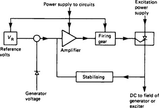
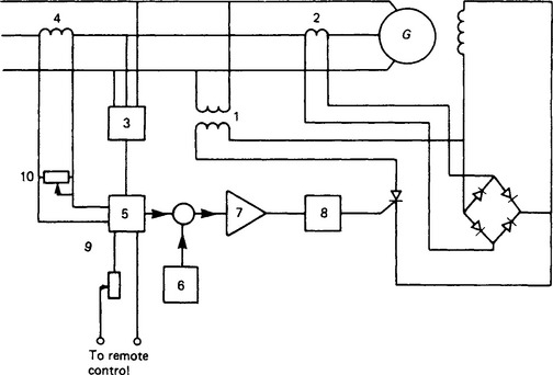
Figure 28.28 Self-excitation with a one-phase thyristor; 1, Excitation transformer; 2, excitation current transformer; 3, voltage transformer; 4, compounding current transformer; 5, voltage-measuring circuit; 6, reference voltage; 7, amplifier; 8, firing gear; 9, voltage-setting rheostat; 10, compounding adjustment
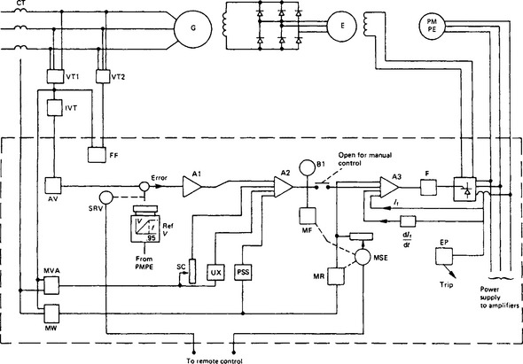
Figure 28.29 Automatic voltage regulator with additional control features: A1, A2, A3, amplifiers; AV, average-voltage circuit; B1, balance indicator; CT, current transformers; E, exciter; EP, excitation protection circuit (operates on high or low excitation current); F, thyristor firing gear; FF, voltage-transformer fuse failure detector and alarm; G, generator; IVT, isolating voltage transformer; MF, manual follow-up circuit (adjusts MSE); MR, manual restrictive circuit; MSE, manual set-excitation control; MVA, MW, circuits providing signals proportional to MVA and MW; PMPE, permanent-magnet pilot exciter; PSS, power-system stabiliser control; Ref V, reference voltage; SC, set-current compounding control; SRV, set-reference voltage control; UX, underexcitation (var limit) control; VT1, VT2, voltage transformers
28.14.7.1 Control range
Generators are usually designed to deliver any load from zero to rated output over a voltage range of ±5%, at any power factor between rated (usually 0.8–0.9 lag) and say 0.95–0.9 lead. The a.v.r. setting controls must provide the corresponding range of excitation, and also provide say 85% of rated voltage on no load. Accuracy of control is usually within ±2.5 or ±1.0% of the set value over the load range.
28.14.7.2 Manual control
Manual control is usually provided for use if the automatic control fails or for convenience when the set is being commissioned. In small units the manually controlled system may be entirely independent of the automatic one, but (especially for economy on large units) it uses the thyristor output stage and the associated firing circuits of the regulator.
Some regulators, when in auto control, drive the manual control so that, if it were in use, it would give the same excitation as the auto circuit. However, this follow-up must be prevented from driving the manual control down to excitation levels that are stable with continuously acting control but unstable with fixed excitation.
Some systems use the manual circuits continuously to control the steady-state excitation. The auto circuits continuously trim this to suit minor fluctuations of load, voltage, etc.; larger disturbances will cause rapid automatic changes of excitation voltage, up to full boost or full buck if necessary. If changed conditions persist for more than a few seconds, the follow-up circuit adjusts the manual control to the new steady state and the auto-circuit output falls to its usual low level.
28.14.7.3 Manual-to-auto change-over
Whichever system is in control, it is necessary to adjust the other automatically or manually, so that a change-over can be made without causing a significant change in excitation. A balance meter is provided so that the outputs of the two systems can be matched before making the change. The manual rheostat and the voltage-setting rheostat are often motorised for control from a remote control room, and the balance-meter reading must be repeated there too, unless automatic matching is provided.
28.14.8 Additional control features
To ensure satisfactory sharing of reactive load between generators paralleled at their terminals, the a.v.r. can arrange for the terminal voltage to fall with increasing reactive load, usually by 2.5–4.0% at full load. For generators paralleled on the h.v. side of step-up transformers, the a.v.r. can either add to or partly compensate for the transformer impedance drop, as desired.
28.14.8.2 Excitation limits
Fault conditions on the power system will cause the excitation to rise to ceiling value to try to maintain normal voltage. An adjustable timer is used to return to normal excitation after several seconds in order to avoid overheating the machines if the fault persists.
A reactive-power-limiting circuit can be used to prevent the excitation falling so low that the generator will not remain in step with the system. The reactive power (under-excited) at which this circuit operates is automatically varied in response to machine voltage and power output to maintain an adequate stability margin.
28.14.8.3 Overfluxing protection
It is operationally desirable to be able to leave the a.v.r. in control when the generator is shut down or run up. To avoid overfluxing the machine and its associated transformer (if any) the reference voltage is arranged to decrease in proportion to frequency at speeds below about 95% of normal. This ‘constant volts-per-cycle’ control is needed also for generators that have to operate over a speed range, e.g. for ship propulsion.
28.14.8.4 A.v.r. fault protection
Failure of a.v.r. components, or of other components in the excitation system, may cause excessive or insufficient excitation for safe operation. Either condition trips the a.v r. to manual control and alerts the operator.
Voltage-transformer fuse failure is detected by comparing the voltages from two voltage transformers. If the a.v.r. voltage transformer fails, the system trips to manual control; if the comparison circuit fails, an alarm shows that fuse failure protection is no longer working.
28.14.8.5 Double-channel a.v.r
To enhance reliability of operation, large or vital generators frequently use regulators in which the automatic and manual control circuits are duplicated; often the thyristor output stage supplying the exciter field is duplicated too. Occasionally the much larger thyristor bridge that feeds the generator field directly may be duplicated. Each channel is able to perform the full excitation duty; the two channels may operate in parallel or in main and stand-by mode. If one channel fails, the other maintains the excitation unchanged. If the second channel fails subsequently, it trips to manual control. Alarms indicate the abnormal conditions.
28.14.9 Overall voltage response
The overall voltage response is defined in terms of steady-state and transient behaviour with the generator on open circuit and on no load, and under the control of the excitation system. For a generator operating alone, the following conditions may be relevant, their importance depending on the duty required of the generator:
(1) Steady state: accuracy of voltage control over the range of load and power factor.
(2) Transient: 1. Response of the open-circuit generator voltage to a step change in reference voltage; 2. Voltage response when a sudden increase or decrease of load occurs.
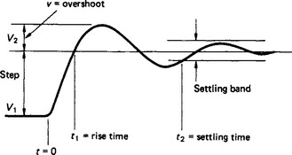
Conditions of importance under transient conditions are the voltage rise and recovery time of the generator voltage when load is suddenly removed, and the voltage dip and recovery time when a large motor is switched on to the generator terminals. For a generator running alone, BS 4999-140:1987, ‘Specification for voltage regulation and parallel operation of a.c. synchronous generators’, specifies various grades of voltage regulation, for steady state and transient conditions. Accuracy of voltage control may conform to ±1% or ±2.5% or ±5%. Voltage dip must not exceed 0.15 p.u. when a current of 0.35 or 0.6 or 1.0 p.u. of rated generator current is suddenly demanded. The voltage is required to recover to 0.94 or 0.97 p.u. within 1.5 or 1.0 or 0.5 s. Values of the temporary voltage rise that occur when rated load at p.f. 0.8 is thrown off are specified with a range 0.35–0.15 p.u. The more severe the conditions the more powerful the a.v.r. control must be. Also, the lower must be the generator X″d and X′d in order to reduce the immediate fall or rise in voltage that the a.v.r. cannot affect. There is a consequential increase in the short-circuit current and in the generator frame size; both these increases raise the cost of the generator and, perhaps, of its switchgear. The response under transient conditions is a convenient way of expressing the overall performance and of testing it during commissioning. The terms used are
| V1 | initial voltage |
| V2 | final voltage |
| V1–V2 | voltage step |
| v | voltage overshoot beyond V2 |
| t1 | rise time, that in which V2 is first reached (and passed) |
| t2 | settling time, the shortest time after which the voltage remains within say ±0.5% of a steady value (which should be V2). Figure 28.30 illustrates a step up of voltage. |
Normally, either V1 or V2 is the rated voltage Vr, depending on whether a ‘step-up’ or a ‘step-down’ change is being tested. The voltage-time curve is a well-damped transient, settling at V2 after a few oscillations. Typical values of the quantities defined above are
For a given step change (V2 − V1), t1 is reduced by increasing the ceiling voltage Vc, by increasing the excitation system gain, and/or by reducing the system time constants. The parameters of the generator and exciter cannot be changed once the machines are made, but the a.v.r. parameters are designed to be adjustable. Changes that reduce t1 will increase the overshoot v and the settling time t2; hence settings of a.v.r. gain, time constants and feedback signals (if any, e.g. exciter voltage or exciter field current) are calculated to achieve the desired compromise, and performance is checked over a range of values of step change during commissioning (say steps of 1%, 5%, 10% and 20% of Vr).
When generators operate in parallel, as most do, the excitation systems must be designed and adjusted to achieve the best compromise between highly accurate voltage control, steady-state stability, and transient stability following a system disturbance. Thus some step-change tests, or tests by injecting low-frequency sinusoidal voltage into the reference circuit, are desirable, to confirm the calculated performance.
See IEEE Standard 421A, ‘Guide for identification, testing and evaluation of the dynamic performance of excitation control systems’.
28.14.10 Digital control170
Increasing use is being made of a dedicated microprocessor to replace the analogue control system. The input signals (voltage, current, MW, MVAR, etc.) are converted to digital form, and the processor is programmed to respond to these to provide an analogue signal to the firing circuits. The characteristics needed in the excitation controller are reproduced digitally in the processor, and limits of relevant quantities are introduced. The whole can be set up and tested in the works, so that site commissioning is simpler and quicker. In service, settings do not drift or suffer from poor rheostat contacts, but can be readily changed, even while the set is in service, to suit changed operating conditions. If a component does fail, a new card can be inserted without repeating the commissioning tests.
There is a delay of up to 10 ms while the microprocessor scans the input signals and readjusts its output signal, if necessary, but this is very small compared with the machine time constants.
The thyristor firing pulses may also be generated digitally. Development is proceeding of adaptive controllers that will automatically tune their characteristics to suit the operating conditions.169
28.15 Turbogenerators92–137
The characteristic features of turbogenerators are their high speed to meet steam-turbine requirements and their large outputs to provide economy of capital and operating costs for the power station. Most are two-pole units running at 3000 or 3600 rev/min, but four-pole generators at 1500 or 1800 rev/min have become common for large outputs (1000 MW or more) from nuclear reactors of the boiling-water or pressurised-water type. These reactors deliver large volumes of steam at temperatures and pressures that are lower than those provided by fossil-fired boilers or some gas-cooled reactors. The low-speed turbine may handle these conditions with a greater efficiency that is sufficient to offset its higher capital cost compared with a high-speed unit. Design constraints are less exacting in the low-speed turbine and generator.
28.15.1 Main dimensions
The output coefficient C ranges typically from about 0.5 MVA s/m3 for a rating of 20 MVA to about 2.0 MVA s/m3 for a 1000 MVA unit. For 3000 rev/min machines these figures correspond to D2L of 0.8 and 10 m3, respectively. Economic diameters for these outputs range from approximately 0.75 m to 1.3 m, the latter being a limit set by centrifugal stresses in the endrings and in the rotor teeth. Hence outputs range from approximately 17 to about 170 MVA per metre of core length. The higher values of output coefficient are made possible by enhanced cooling techniques. Typical dimensions for a 660 MW two-pole hydrogen-cooled machine may be: rotor diameter, 1.15 m; core length, 6.8 m; overall shaft length, 13.5 m; core outside diameter, 2.7 m; outer casing, 4.8 m in diameter and 10.3 m long; total weight, 480 t.
28.15.2 Rotor body
The output available from a turbogenerator is largely determined by the excitation m.m.f. that can be carried on the rotor with acceptable winding temperatures. The high centrifugal stresses make cylindrical (i.e. non-salient-pole) construction essential.92,93 Within the chosen diameter the number, shape, size and spacing of the winding slots have to be optimised to obtain the maximum m.m.f. capability with acceptable stresses in the teeth and slot wedges, with adequate insulation, with acceptable magnetic flux densities and with ducts for ventilation that enable temperature guarantees to be met. For air-cooled machines of medium output the manufacturing simplicity afforded by parallel-sided slots and solid copper conductors of rectangular cross-section may outweigh the loss of optimum performance and provide the cheapest design. For larger ratings tapered slots are used to accommodate more copper, while giving approximately constant mechanical stress and magnetic flux density along the radial length of the teeth.
A rotor is forged from a single steel ingot, the largest of which approach 500 t in weight; this would produce a rotor weighing 250 t, enough for a four-pole machine of about 1250 MW at 1500 rev/min. The forgings contain the alloying elements nickel, chromium, molybdenum and vanadium; according to size and speed, ultimate tensile strengths of the forgings range from 650 to 800 MN/m2, while their 0.2% proof stresses range from 550 to 700 MN/m2. The forgings are inspected with ultrasonics and magnetic-particle ink before use. Many generator makers now rely on these examinations and do not bore the forging axially along its centre line, except for large forgings or if ultrasonics reveals defects that can be removed by boring.
The endwindings (the parts projecting beyond the ends of the slots) must be supported against centrifugal forces by endrings (retaining rings) from which they are insulated by, for example, resin bonded fibreglass or aramid paper (Nomex) or combinations of synthetic insulating sheets. The endrings are steel forgings, usually shrunk on to the ends of the rotor body. In some older designs they were shrunk on to discs that were shrunk on to the shaft outboard of the windings, and they were not tight on the rotor body.
From the 1950s until 1982, the endrings106,107 were of austenitic steel (18% Mn, 4–5% Cr, 0.3% C) warm worked to give high strength, up to 1100 MN/m2 proof stress and 1220 MN/m2 ultimate in the highest grade. This alloy is very susceptible to stress corrosion if it gets wet, e.g. by condensation from moist air or leakage of cooler water. In 1982 an austenitic alloy became available with 18% Mn, 18% Cr;108,109 this is not subject to stress corrosion under any likely operating conditions, and has mechanical properties up to 1200 MN/m2 proof stress (0.2% strain) and 1300 MN/m2 ultimate strength. Endrings large enough for 1500 MVA two-pole or four-pole generators can be obtained, and higher strengths have been developed. Many endrings of the older alloy have been replaced, after some years in service, using the 18–18 material.106,116
Rotor vibration at running speed must be low—typically about 50 μm peak-to-peak measured on the shaft near the bearings, though up to twice this is commercially acceptable. Hence balance weights must be carefully positioned, axially as well as circumferentially, and the design of the rotor, its bearings and its supports must ensure that its critical speeds are sufficiently far from rated speed. Small 3000 rev/min rotors will have one critical speed below 3000 rev/min, say about 1700–2000 rev/min, but as ratings (and therefore the bearing span) increase, two or even three criticals will occur below 3000 rev/min (typically around 650, 1750 and 2500 rev/min). When the rotor is coupled to the turbine, the critical speeds are usually raised slightly, so that behaviour in both the coupled and the uncoupled condition must be acceptable, for site running and works testing (without the turbine) respectively.
Electrical faults on the power system or on the machine itself produce abnormally high oscillatory torques on the rotor, at system frequency and often at twice this frequency also. Where series capacitance is used in long lines to compensate for inductive reactance drop, electrical oscillation at the natural frequency fn may cause torques on generator rotors at system frequency minus fn. These torques may resonate with torsional natural frequencies of the shafts and produce unacceptable fatigue stresses. From all these causes, complex torsional oscillations develop in the shaft system, with components determined by the inertias and stiffnesses of the several shafts of the turbine, generator and exciter. The shaft dimensions must be chosen to avoid a serious loss of fatigue life during such incidents as well as to satisfy the critical speed criteria mentioned above. There are many articles on the subject; references 128–135 are a few of these.
Bearings are of the white-metalled cylindrical type, with forced oil lubrication and, except on small sets, high-pressure oil jacking also. Jacking allows the set to run slowly (typically 3–20 rev/min) on the turning gear to cool off the turbine and generator rotors before the unit is finally stopped. Without this, the rotors would bend because temperature gradients would occur across the diameter of each rotor, and vibration would occur on the next run-up.
All turbogenerator rotors bend under their own weight, and with two-pole rotors for outputs more than about 30 MW the amount of bend would be significantly more when the pole axis is horizontal than when it is vertical. Hence a vibration would occur at a frequency corresponding to twice the running speed; it is caused by the changing stiffness of the rotor in the vertical plane, and therefore cannot be removed by mechanical balancing. The stiffnesses about the polar (direct) axis and the slot (quadrature) axis must be made as nearly equal as possible under running conditions (when centrifugal force on the windings increases the stiffness in the plane of the quadrature axis). This is done either by cutting axial slots along the pole areas (and filling them with magnetic steel if necessary to avoid magnetic saturation) or by cutting narrow arcuate grooves circumferentially across the poles, sufficient grooves being spaced down the length of the rotor to reduce the stiffness to match that in the quadrature plane.29,93
28.15.3 Rotor winding
Excitation currents range from say 400 A at 200 V for a 30 MW generator to 5.7 kA at 640 V for a 1000 MW two-pole machine and up to around 7 kA at 650 V for a 1500 MVA machine. For rotors using indirect cooling each coil is wound with a continuous length of copper strap, bent on edge at the four corners. The copper contains about 0.1% silver and is hard drawn to increase its strength and so avoid the coil-shortening effect that occurred with plain soft copper as a result of heating while part of the copper was prevented (by centrifugal force) from expanding axially.
Directly cooled coils are usually made of larger section conductors of silver-bearing copper containing grooves and holes to provide gas passages. Half-turns are brazed together in the end regions after they have been positioned in the rotor slots. The slots may be parallel-sided, or tapered to contain more copper without increased tooth stress.
Insulation between turns is usually provided by interleaves of resin-bonded glass fabric or some other synthetic material. The coils are insulated from the rotor body by U-or L-shaped troughs of resin-bonded fibreglass, Nomex or melamine, or combinations of such materials. Similar insulating strips insulate the top conductor from the slot wedge; in direct-cooled rotors the strips must have through-holes to allow the cooling gas to escape from the rotor; they must be thick enough to provide adequate creepage distance to withstand the specified h.v. tests.
The end-windings are packed, partly or wholly, with blocks of insulating material to avoid distortion and the consequent risk of short circuits between turns.
28.15.4 Stator core
The stator core is built up of segments of electrical sheet steel, usually 2–3% silicon, 0.35 mm thick, cold rolled and non-oriented. To minimise weight, the core is worked at the highest flux density consistent with reasonable losses. In a two-pole machine the magnetic force across the airgap subjects the core to an elliptical distortion that rotates with the rotor, so producing a double-frequency (2f) vibration. The core depth must be chosen so that its natural frequency of vibration in this elliptical mode is well away from 2f; usually 3f or more is practicable without excessive depth of core. Grain-oriented steel has better permeability and lower losses than non-oriented steel, but as it has a lower modulus of elasticity its other advantages cannot be realised without accepting higher vibration. This, and its higher cost, severely limit its use in turbogenerators.
28.15.5 Stator casing
Air-cooled machines may have bearing pedestals on a bedplate; the stator frame then merely supports the core and forms the ventilation enclosure. Alternatively, it may be a more rigid box frame with the rotor bearings carried in end-brackets.
A hydrogen-cooled machine must have a totally enclosed and gas-tight construction; the end-bracket bearing arrangement is adopted to minimise the bearing span and to raise the critical speeds. Hence the frame must be rigid enough to provide proper support for the bearings and to contain the gas pressure that might occur in the unlikely event of a hydrogen—air explosion inside the frame. This could produce pressures up to about 1400 kN/m2; therefore this pressure, rather than the continuous working pressure of hydrogen, becomes the design criterion.
In large two-pole machines (which are invariably hydrogen cooled) some form of flexible mounting is needed between the core and the casing, and the casing should not have any natural frequency near to 2f. This is to avoid excessive magnetic noise and the risk of unacceptable vibration on the casing, coolers or pipework.
Where transport facilities are inadequate for handling the complete stator, the core and windings must be made separately from the outer casing, separately transported, and assembled on site before the rotor is inserted. By contrast, smaller machines can be transported complete to some sites, with the rotor clamped in temporary supports; this arrangement facilitates erection.
28.15.6 Stator winding
For small machines the voltage is usually fixed at a standard network voltage (e.g. 6.6 or 11 kV), but for large machines, where a generator-transformer is used, the designer has a free choice. A high voltage avoids difficulties due to high currents, but valuable space in the slots has to be sacrificed to insulation; a compromise is thus about 15 kV for 100 MW and 200 MW machines, and up to 22 or 25 kV for the larger sets. Even so, generators of more than about 50 MW rating will have two circuits in parallel per phase; for more than 1000 MW it may be necessary to use special winding arrangements to have four parallel paths in a two-pole machine. In four-pole generators, four circuits occur naturally and can be in parallel or in series-parallel.
The winding is of the two-layer basket type, almost always with integral slots per phase per pole, as described in Sections 28.3 and 28.4. In the slots27 and in the endwindings101 the coils must be supported to resist electromagnetic forces.93 These are, on normal load, continuous though fairly low vibratory forces at twice supply frequency. When a short circuit occurs close to the generator, transient oscillatory forces occur, 50–100 or more times greater than those on load.
In the slots the forces are radial, directed towards the bottom of the slot, except where different phases occupy the same slot; there the force on the top conductor is towards the wedge for part of each cycle. To support the coils along the whole core length, conformable packing strips of, for example, resin impregnated polyester fleece are placed beneath and between the coil sides. Slot wedges are fitted that apply a known radial load to the coils, greater than the electromagnetic forces. Packing may be fitted down the sides of the coils, and there may be a fibreglass ripple spring between the wedge and the top coil side to take up any small shrinkage in service.27,29,93
The endwindings are secured to a strong structure of insulating materials,27,29,93,100 fibreglass rings carried on brackets of resin-bonded wood laminate have been used very widely. For larger ratings a solid cone of filament-wound resin bonded fibreglass is used for greater strength and long-term rigidity. The coils are bedded to the structure with conformable packing material. Usually the slot and endwinding packings are cured while the coils are held by temporary wedges and clamps, which are then replaced by the permanent ones. The complete structure is bolted to the end of the core; some axial movement may be allowed, to accommodate expansion of the coils relative to the core.
28.15.7 Cooling
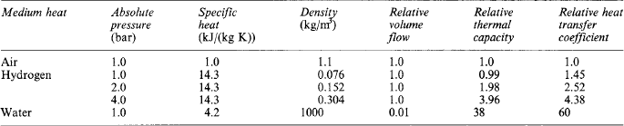
Efficiencies are between 96.5% and 99%, increasing with the rated output. However, the losses will be 0.5–15 MW, appearing as heat that must be removed by circulation of an appropriate cooling medium: oil for removing bearing-friction losses, and air, hydrogen or water for other losses. Details of the cooling media used for stator and rotor windings are given in Table 28.6. The heat transfer coefficients are typical, but depend considerably on velocity and duct size.
Traditionally, indirect air cooling was adopted for outputs up to 70 MVA, and indirect hydrogen cooling for outputs above about 50 MVA. Direct hydrogen cooling of rotors developed rapidly for ratings from about 100 MVA up to the largest, about 1500 MVA, that have been built. Some manufacturers used hydrogen cooled stator coils up to about 650 MVA: others adopted water cooling above about 150 MVA where indirect cooling was becoming difficult. In recent years cheap and simple designs have been developed up to 200 MVA rating using air cooling, direct in the rotor winding and indirect for the stator.
28.15.7.1 Indirect cooling
The cooling medium (air or hydrogen) is blown along the airgap, through ducts in the core and over the surface of the windings. Thus heat generated in the winding passes through the main insulation to the rotor and stator teeth, respectively, and is picked up by the cooling gas mainly from the iron surfaces.
With air cooling, closed-circuit ventilation is universal except in the very smallest sizes, and coolers are separately mounted—usually in a basement beneath the generator, but occasionally above or at the side of the machine. With hydrogen cooling, however, there is no alternative but to build coolers within the gas-tight explosion-proof structure of the machine itself. Figure 28.31 shows a simplified diagram of a hydrogen-cooled machine with its gas system. It has directly cooled windings.
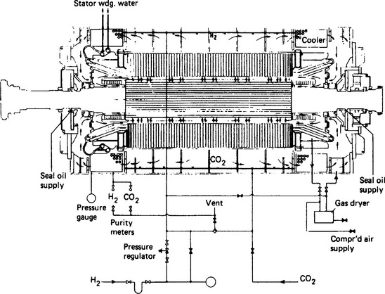
Figure 28.31 Section of a turbogenerator with simplified hydrogen cooling and water-cooled stator winding
The cooling gas is usually circulated by a fan at each end of the rotor, though many air-cooled generators (30–60 MW or so) had motor-driven fans mounted in the basement with the air coolers. The rotor fans may be of the centrifugal or the aerofoil (axial-flow) type. Their main purpose is to establish the gas flow through the stator frame, core and coolers; the flow through the rotor results mainly from its own rotation. Most indirectly cooled rotors have axial ventilation slots in the teeth that are closed by wedges except near the middle of the rotor body where the flows from each end emerge into the gap and then pass through the radial ducts in the stator core to the back of the frame.
Pure hydrogen has a density approximately 1/14 that of air, while its specific heat is 14 times that of air; it has a higher heat transfer coefficient and much better thermal conductivity. In service there may be about 1% impurity consisting of air and carbon dioxide; this increases the density by about 13%, but has no significant effect on the cooling properties listed in Table 28.6. Windage losses are proportional to density, but even at an operating pressure of 5 bar (absolute) they are still only 40% of what they would be in air at atmospheric pressure.
Early hydrogen-cooled machines were designed to operate at just above atmospheric pressure, but raising the pressure to 2 bar (absolute) and then to 3 bar raised the output available from a given frame size by approximately 15% and then by a further 10% respectively. No worthwhile improvement occurs above 4 bar (absolute) because the temperature gradient across the winding insulation is a large part of the permissible temperature rise.
The auxiliary equipment for hydrogen-cooled generators divides into two main groups: gas control and seal-oil treatment.
The gas control system provides means for filling and emptying the casing without risk of forming an explosive hydrogen-air mixture. Carbon dioxide is used as a buffer, and mixtures containing more than 5% hydrogen in air, or more than 5% air in hydrogen, are avoided. In service the rate of hydrogen loss, though small, is sufficient for the purity to settle at 98–99% hydrogen as make-up is added to maintain the desired operating pressure.
The shaft seals, which prevent leakage of hydrogen along the shaft to the bearings, are supplied with oil maintained at a pressure above the gas pressure. Ring seals which encircle the shaft are simple and allow free axial expansion of the shaft; however, they also allow a significant rate of oil flow towards the hydrogen side of the seal, and rather more to the air side. The gas-side flow absorbs hydrogen, and would release air or moisture into the machine if it contained these in solution. To avoid the consequent pollution, and loss, of the hydrogen, the oil is vacuum treated before being fed to the seals, and the hydrogen-side oil passes through detraining tanks to allow entrained hydrogen to return to the frame before the oil is vacuum treated and recirculated.
The face, or thrust, type of seal is a ring, usually of white metalled steel, which operates against the radial face of a collar on the shaft. The hydrogen-side oil flow is insignificant, so vacuum treating is unnecessary. The extremely thin hydrogen-side oil film (say 60 μm) makes the seal rather vulnerable to dirt particles, and if the ring does not slide freely to follow shaft expansion it will leave the collar and allow leakage or will suffer excessive face pressure and damage to the white metal. Both types of seal are in satisfactory operation. A doubly fed ring-type seal offers the advantages of both types, provided that the pressures of the two systems are kept accurately balanced so that the hydrogen- and air-side flows are kept separated.
A wide range of indicators fitted with audible and visible alarms is necessary to indicate any departure from normal operation of the various parts of the gas and oil systems.
28.15.7.2 Direct cooling27, 29, 123–127
Hydrogen The winding conductors are much more effectively cooled by passing the coolant through them in direct, or almost direct, contact with the copper. Hence much higher current density is possible with an acceptable temperature rise, and the output per unit volume of active material can be greatly increased. Furthermore, significant improvement in performance with hydrogen cooling is obtainable up to operating pressures of 5 or even 6 bar (absolute) (500–600 kN/m2). In the rotor, several flow arrangements are used:
(1) Axial flow The gas enters tubular, or axially grooved, conductors in the end-winding region and leaves radially through a group of holes through the conductors and wedges at the mid-length of the rotor.
(2) Axial flow This is as for (1), but for longer rotors. The middle quarter (approximately) is fed from subslots, while the two end-portions are fed as in (1).
(3) Radial The gas enters each end of a subslot cut beneath the winding slot and flows radially outwards through holes punched through the flat copper strips and insulation, distributed throughout the rotor length.
(4) Axial—radial This is a combination of (1) and (3) using axially grooved conductors in which the radial exit holes are displaced axially from those that feed gas from the subslots.
(5) Gap pick-up Specially shaped holes in the wedges ‘scoop up’ gas from the gap, and others eject it after it has passed through cooling ducts formed in the copper by punched holes or transverse grooves.
Types (1) and (2) require high-pressure axial-flow blowers, which may have three to seven stages of blades; (3) and (4) rely almost wholly on the self-ventilating action of the rotor; (5) may be applied by dividing the rotor into axially adjacent inlet and outlet zones, which may be co-ordinated with the stator ventilation zones. All these schemes are used for hydrogen-cooled machines up to the largest ratings. Type (3) is now common for air-cooled machines with totally enclosed air circuits.
Directly hydrogen-cooled stator coils are used by some makers up to ratings of 600 MW or more. The gas flows down thin-walled bronze or stainless steel tubes that are bonded among the conductor strips and lightly insulated from them. Entry and exit has to be at the ends of the coils, so a moderately high pressure differential is needed. The system co-ordinates well with rotor ventilation of type (1) or (2).
Water The high heat-removal capacity of water and its low viscosity allow it to be used in tubular subconductors that are still small enough to keep the eddy-current losses low.
At each end of the conductor the subconductors (tubes and strips, or all tubes) are brazed into a water box. The coil-to-coil current-carrying connection may be tubular to carry the water also, or separate connections may be made. The water boxes are connected to the inlet and outlet manifolds by insulating pipes of polytetrafluoroethylene (PTFE) or some other synthetic material. Water taken from the boiler make-up system is circulated by pumps around a closed pipework system containing the winding, coolers, filters, control valves and monitoring instruments. Water conductivity is easily maintained by using a demineraliser unit, usually of the resin-bead type; less than 10 μS-cm is easily attained, and the leakage currents down the water columns are insignificant.
The temperature difference between copper and water is only about 2°C, and the water temperature rise between inlet and outlet is usually about 25–30°C. The inlet water pressure is kept below the hydrogen pressure; if leakage does occur, it is leakage of hydrogen into the water (easily detected), and water does not enter the machine.
Water-cooling of the rotor winding increases the output available from given frame size; the slots can be smaller, leaving more room for magnetic flux, so the machine can be shorter provided the stator design is adjusted to suit. Constructional problems occur because of the need to convey water to and from the rotor, to accommodate water manifolds on the shaft, to support the water-pipes against centrifugal force, and to design them and the winding to withstand internal pressures (produced by rotation) up to around 15 MN/m2. Nevertheless, such rotors are in successful service though they have not yet been widely adopted.
Direct cooling allows the specific electric loading to be increased without exceeding the permitted limits of temperature rise. A smaller frame size can be used for a given output, but the leakage reactances are increased by the increase of leakage flux compared with main airgap flux. The values of Xd and short-circuit ratio can be maintained by lengthening the airgap, until the increased excitation on load pushes the rotor winding temperature rise to its limit.
28.16 Generator-transformer connection
For small ratings up to 3 MW, single-core cables are used. For ratings above this where the number of cables needed would be excessive or cannot be accommodated, solid copper or aluminium bus-bars are used. The bus-bars are supported on insulating cleats or ceramic post insulators and are enclosed in a surrounding duct which provides mechanical protection and sealing. The bars are spaced and supported to suit the operating voltage, the current to be carried (taking into account skin and proximity effects which raises the a.c. resistance and leads to extra heating) and the electromagnetic forces produced by short-circuit currents. The phases are sometimes segregated by insulating barriers to achieve the creepage and clearance distances required. For higher current ratings, each phase conductor usually consisted of two angle- or channel-section bars mounted face to face to form an open diamond or box-shaped section. These sections and arrangements give lower skin-effect losses than flat rectangular bars of the same weight, and natural air cooling may be adequate up to at least 200 MW (with a corresponding current of the order of 10 kA).
To avoid the possibility of phase-to-phase faults, however, phase-isolated bus-bars were adopted for ratings above about 200 MW, and now above 60 MW. Each line connection consists of two angle- or channel-section bars supported by post insulators inside an aluminium tube which is physically and electrically continuous along its length. The tubes of the three phases are connected together electrically at each end of the run and are joined mechanically to the generator and transformer frames. Thus only phase-to-earth faults are possible. Eddy currents induced in the aluminium tubes cause additional losses, but they confine the magnetic field largely within the tube, so that heating of the foundation steelwork or other structures is avoided.
For the higher ratings, say above 12 kA, each conductor bar may be of semi-hexagon or semi-octagon shape, so that the complete conductor approximates to the circular cross-section that gives minimum skin effect and minimum loss.
Natural air cooling is practicable up to about 20 kA, but a significant reduction in cross-section or an increase in current rating is made possible by forced-air cooling. A maximum conductor temperature rise of 55°C above the ambient air is usual. With this, and a continuous rating of 19.5 kA (660 MW at 23 kV, 0.85 p.f.), typical dimensions are as given in Table 28.7.
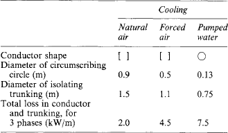
For forced-air cooling, the flow is usually from one end of the run to the other along one phase, half the flow returning along each of the other two phases. The air circuit is totally enclosed, with an air-to-water heat-exchanger extracting the loss. If the air circulation fails, the naturally cooled rating is about 60% of the forced-flow rating.
The use of water-cooled stator windings led to the development of water-cooled connections in solid tube or cable form. The water-cooling circuit is similar to, but usually separate from, that for the generator stator. The smaller dimensions are an advantage where space is limited, and the greater loss is not usually economically unacceptable. The system has not been widely adopted, however, because there is usually room for air-cooled connections, while the extra water-cooling auxiliaries introduce additional maintenance and extra complications of duplication and control to guard against shut-down of the generator if an auxiliary item fails.
28.17 Hydrogenerators
28.17.1 Introduction26–28, 30, 53, 138–156
The design of hydrogenerators is determined mainly by mechanical considerations. Outputs range from less than 1 MVA to over 800 MVA, and speeds from 50 to 1000 rev/min, depending on the water head available and the type and size of the turbine. The low speeds require the generators to be physically large, and it is often necessary to transport them to site in sections. The inertia required in the set is determined by turbine governing or speed regulation requirements, or by the transient stability of the associated power system. The turbine contributes little flywheel effect, so the generator inertia must often be more than that of a design that satisfies the electrical specification in the least expensive way. The diameter must be increased, or in extreme cases a separate flywheel coupled to the shaft. This is often the best arrangement in fairly small horizontal shaft units.
A water turbine runs up to a high overspeed when load is suddenly removed, because the flow of water cannot be suddenly stopped without causing a high and probably damaging rise of pressure at the turbine gates or valves. The ratio of overspeed to normal speed is, approximately, for impulse turbines (Pelton) 1.7 to 1.9, for reaction (Francis) 1.8 to 2.1, and for propeller (Kaplan) 2 to 2.2. If the governor should fail during load rejectien, a Kaplan turbine could run up to 3 times normal speed.
The rotors must be designed to be safe at overspeed, where the factor of safety on the proof stress of the material used is normally not less than 1.5. A figure closer to 1.1 is acceptable for the very rare runaway condition of a Kaplan unit.
The first critical speed is required to be above the overspeed.
28.17.2 Construction
28.17.2.1 General arrangements8,26,30
Horizontal and vertical shaft arrangements are used, the former usually for impulse turbines and small reaction turbines, the latter for large reaction and propeller turbines. Nevertheless, the vertical arrangement has been used up to 36 MVA and 1000 rev/min, and the horizontal shaft up to more than 100 MVA at 428 or 600 rev/min.
Horizontal generators are similar to those made for diesel engine or geared turbine drive, except that they must accept the higher overspeed, may carry a flywheel, and need a thrust bearing to carry any unbalanced hydraulic thrust. A turbine may be overhung at each end, or at one end only.
With a vertical shaft, five bearing arrangements are possible. These are shown in Figure 28.32. The umbrella arrangements of (d) and (e) are suitable for low-speed sets in which the ratio of core length to stator bore diameter does not exceed say 1/4. With a top guide bearing added as at (c), higher speeds and an L/D of 1/3 are practicable. The top thrust bearing arrangement of (a) and (b) is used, where necessary, for higher L/D ratios and speeds usually above 400 rev/min. The top bracket and the stator frame must be rigid enough to carry the thrust load, and so are more expensive than with a bottom bracket assembly. However, as the bearing is on a smaller diameter part of the shaft, its losses are less; if the contract places a high value on losses (as with pumped storage for example) the capitalised value of the lifetime losses may be enough to pay for the top-thrust layout. If the bracket is supported directly from the pit walls, the stator frame is relieved of the thrust load, and some problems of differential expansion and electromagnetic vibration are avoided.
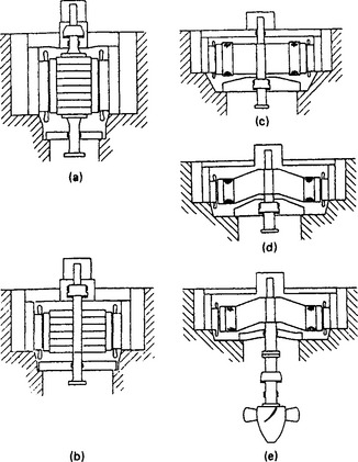
Figure 28.32 Hydroelectric generator bearing arrangements: (a) thrust bearing above rotor, two guide bearings—upper guide bearing separate from and below thrust bearing; (b) thrust bearing above rotor, two guide bearings—upper guide bearing combined with thrust bearing; (c) thrust bearing below rotor, two guide bearings (semi-umbrella machine); (d) thrust bearing and single guide bearing below rotor (umbrella machine in English, American and Continental literature); (e) thrust bearing mounted on turbine casing, single guide bearing below generator rotor (umbrella machine in German literature). (Reproduced, with permission, from Anscombe30)
28.17.2.2 Thrust and guide bearings
In large vertical machines the dead weight plus hydraulic thrust is several hundred tonnes. The thrust collar rests on segmental pads (usually of steel) faced with white metal. They are supported on a thrust ring at the bottom of the annular oil chamber that surrounds the shaft. The pads and the lower part of the collar are submerged, and careful design and assembly are needed to avoid leakage of oil and vapour.
The pads are supported so that they can tilt slightly to develop hydrodynamic lubrication. The Kingsbury pad is supported on a single spherical pivot: the Michel pad pivots on a radial ridge. Both supports are offset from the centre line of the pad if rotation is to be in only one direction: a pivot on the centre line is needed for a reversing pumped storage set. Load sharing among the pads depends critically on the accuracy of dimensions or adjustment of the pad heights. This difficulty is much reduced if the pad sits on a mattress of closely spaced helical springs instead of a solid pivot. The specific bearing pressure can be quite high, up to 3.5 MPa average over the pad surface. Transient conditions on a pump/turbine unit may increase this at some times by a factor of about 1 1/2. The peak oil pressure on the pad is about 1.5 times the average. The oil film thickness is usually between 0.1 and 0.05 mm. On such highly loaded bearings a high pressure oil supply is often fed through one or more small holes in the surface of the pad to provide oil jacking and hydrostatic lubrication at rest. This is especially needed to reduce the starting torque required when the unit is being motored for pumping duty.
The pumping action of the bearing is often enough to circulate the oil through water-cooled heat exchangers placed in the oil pot. If the pot is too small for this, or to improve accessibility to the pads, the coolers may be mounted separately below the bearing. The oil is then circulated by main (a.c.) and stand-by (d.c.) motor driven pumps.
With high bearing pressures and surface speeds cooling water may be circulated through channels in the pads themselves.
Vertical shaft machines have friction brakes operated by air pressure to bring the set to rest without protracted running at low speeds, when the lubrication of the thrust pads may become inadequate. To reduce wear on the brake pads they are not applied at or near the full speed except in an emergency. Dynamic braking is achieved by circulating up to full-load current through the stator winding short-circuited by a braking switch. The friction brakes are then applied at 15–20% of full speed.
The brakes can also be operated by oil pressure when the machine is stationary, to lift the thrust collar off the pads, either to flood the surfaces with oil after prolonged standing, or for maintenance such as inspection or removal of the thrust pads. If the shaft is to remain lifted for a long time, the jacks are locked mechanically to allow the oil pressure to be removed.
Guide bearings are usually of the pivoted-pad type, running on the outside of the thrust collar or a smaller diameter of the thrust block. Where the guide is remote from the thrust bearing, it runs on the shaft in its own oil enclosure.
If there is a bearing above the rotor, it needs to be insulated to prevent the flow of shaft currents caused by some asymmetry in the core flux, e.g. differences in reluctances at the joints in the core. With a top thrust bearing the thrust face, which is normally a renewable ring bolted to the collar, can be insulated from the collar.
28.17.2.3 Rotor
For large machines the cheapest construction is to secure a laminated rim143,149 to a fabricated spider that is shrunk on the shaft. The rim must carry its own hoop stress plus the load of the poles and coils. Laminations of rolled steel plate commonly have 0.2% proof stress of 450 MPa, suitable for rim speeds up to about 170 m/s at overspeed. Proof stress up to 700 MPa can be obtained, if necessary.
Sheet can be obtained of quality and width suitable for rims up to approximately 1.5 m diameter, so these can be built of complete rings, shrunk and keyed to the spider with enough interference to maintain contact at overspeed. Larger diameter rims have to be segmental; they will come free at just above running speed, but are kept true to the spider by keys that allow radial growth but not tangential movement. Some designs rely upon this key location, and do not have a shrink fit.
Two kinds of rim are used. The so-called chain rim uses segments about 5 mm thick spanning two or more pole pitches, clamped axially by close-fitting bolts. By suitably overlapping the segments and distributing the bolts, the rim can have a hoop strength up to 75% of that of a solid rim. The friction rim is being increasingly used. It has segments about 2 mm thick, to increase the number of surfaces in contact. They are clamped with high pressure by high tensile bolts in holes with some clearance. To build a good rim of either type the segments must be flat and of uniform thickness, and accurately aligned to ensure accurate dimensions of the keyways and the axial T-slots for the pole fixings.
Smaller rotors for 600 rev/min or more, especially horizontal ones, are built of discs up to 150 mm thick, shrunk on to a shaft, or spigotted together and held by through bolts, with bolted-on stub shafts. The diameter is limited by the size of plate available of suitable thickness and quality.
Poles are now most frequently built up of laminations about 2 mm thick. They, like the rim, carry unidirectional flux, so tensile strength, flatness, uniform thickness and magnetic permeability are important. It is not usually thought necessary to insulate the laminations, though this would reduce the surface losses caused by harmonic fluxes in the airgap. The laminations are clamped tightly between heavy steel endplates, cast, forged or fabricated depending on the load imposed by their own centrifugal force and the end turns of the field coil.
Poles are fixed to the rim by dovetail, or more often by T-head, projections. These are secured in corresponding axial slots in the rim by taper keys driven in from each end. These pull the base of the pole against the rim. Large rotors may use as many as nine T-heads per pole; detailed analysis of the stress distribution is needed, e.g. by a finite element technique, to ensure that they share the total centrifugal force reasonably equally.
Copper damper bars, usually uninsulated, are fitted reasonably tightly in semi-closed axial slots in the pole face. They are brazed at each end to a copper segment to form a closed grid. Currents induced in them help to reduce the oscillations of load angle when a disturbance occurs on the power system, and to counteract the negative sequence stator current of unbalanced loads. Pole-to-pole links are sometimes fitted to make the grids into a complete cage, but in large machines centrifugal force and fatigue stresses can cause mechanical failures. If interconnection is needed, it is usually sufficient to braze the bars to a few thick copper laminations next to the end clamps of the poles. These provide satisfactory contact to the rim, which completes the circuit between poles.
Field coils on very small machines have several layers wound with round or roughly square-section copper, enamelled and wrapped with resin impregnated insulating fibre or braid. Larger rotors have coils wound with bare copper strip, bent on edge, and larger rotors still143 use coils fabricated from straight lengths of rectangular section copper strip, brazed together at the corners. The cooling surface is increased by making some strips wider than the others, and placing these, singly or say in pairs, every few turns. With continuously wound strip-on-edge coils the finned effect can be produced conveniently on the sides or the ends of the coil, but not on both.
Insulation between turns consists of two layers of polyimide or aramid paper, or woven glass, with a thermosetting resin. After the coil has been consolidated by baking it under pressure, the interturn insulation is approximately 0.3 mm thick.
Wire-wound coils may be wound directly on to the insulated pole. Strip-on-edge coils may go directly on to the insulated pole, or on to a separate insulated spool which is then secured to the pole. Thick washers of resin—synthetic paper or resin—glass insulate the coil from the rotor rim and from the pole shoe, unless the spool has insulated flanges that do this.
Coil-to-coil connections are secured to the rim, the connection to the top turn (i.e. the outermost one) of a strip-on-edge coil may be brought down inside the coil, between it and the pole, then out beneath the bottom turn. Connections should preferably be arranged to carry the field current equally clockwise and anticlockwise round the shaft. Otherwise it will be magnetised axially, and the bearing surfaces may be damaged by induced currents.
Centrifugal force on the sides of the coil has a component tending to bow the turns, i.e. to bend them on edge away from the pole. To resist this one or several V-blocks (depending on the axial length) are secured to the rim between the poles. Pieces of insulating board of course are fitted between the bare copper and the metal V-block. It is often required that poles may be removed without removing the rotor from the stator bore, and V-blocks make this difficult to arrange. Therefore in some designs, the coils are held by clamps that are secured to the pole itself; the two parts of each clamp are tightened together after the coil and its insulation have been fitted. Then the pole, coil and clamps can be withdrawn as a unit after the pole keys have been released.
28.17.2.4 Stator frame and core26,143
The frame is a fabricated assembly of rings of steel plate connected by axial members of tubular, angle or channel section. It is often necessary to split the frame and core of a large vertical shaft machine into several segments for transport to site. These must be bolted together accurately to form a true circle, with the joint faces of the core fitting extremely closely together.
The core joints are avoided if the core is built into the assembled frame sections on site.
The lower endplate of the frame is bolted to the foundations; if the machine has a top thrust bearing the frame may have to support the thrust load as well as the core and windings.
The wrapper plate round the outside of the frame will usually have openings to receive the air-to-water heat exchangers.
The core is built of cold-rolled silicon steel, usually 0.35 or 0.5 mm thick. The reduction of loss that could be obtained with oriented-grain sheet is small, and rarely enough to justify the higher cost of it. The coreplates are assembled with spacers to form radial ventilating ducts, and are clamped between strong endplates.
28.17.2.5 Stator winding (see Section 28.4)26,53,143
This is usually of the two-layer, fractional-slot type, using diamond coils with either lap or wave connections. The number of slots is often chosen to permit two or more parallel paths per phase, depending on the number of poles. Coils may be pulled, formed or made as single bars, depending on size. In large high-voltage machines they must be firmly secured in the slots and endwindings, especially if they are to suffer much thermal cycling, e.g. in pumped-storage units. Proper earthing in the slots and stress grading for a distance beyond the slot ends are essential to avoid surface discharges. Large and important machines now often have permanent instruments to give warning of any increase in electrical discharges in service.
28.17.3 Cooling
Except for small machines, closed-circuit air cooling is used. Most hydrogenerators rotate in one direction only, and radial-flow or axial-flow fans mounted on the shaft are commonly used. The heat is removed by air-to-water heat exchangers mounted on the back of the stator frame. About 4 m3/s of air is required per kilowatt of loss removed. In cold climates, some of the hot air may be taken from the machine and used for heating the station.
Reversing sets for pumped storage would have to use radially bladed fans, which have poor performance and efficiency. For these machines, and for highly rated machines needing carefully controlled ventilation, several motor driven fans are used.
Hydrogen cooling has not been applied to hydrogenerators, mainly because of the cost and practical difficulties of making an explosion-proof casing. However, when inertia is not a controlling factor, a useful reduction in physical size can be achieved by water cooling the stator or rotor windings, or both.26 Water cooling of only the stator winding introduces a multiplicity of joints which must not leak, but greatly increases the current capacity, or conversely allows the slot size to be reduced for a given rating; this slightly reduces the outside diameter of the core and significantly reduces the leakage reactance.
Water cooling of the rotor winding introduces more constructional difficulties and affects the design more profoundly. The excitation capability is increased without risk of exceeding the specified temperature limits, so a higher short-circuit ratio (longer airgap) is possible, improving the underexcited (line charging) capability. Alternatively a smaller machine with higher electric loading is possible with the stator design suitably adjusted. However, it may be necessary to adopt a size larger than the smallest determined from purely thermal considerations. This larger size may be needed to attain the desired inertia constant, or the lower capitalised cost of its lower losses may be enough to offset the lower first cost of the smaller frame. In some circumstances, water-cooled stator and rotor windings may be economically justified at ratings as low as 150 MVA; conversely, water-cooled stator windings with some form of improved air cooling for the rotor may be preferred on grounds of adequacy and simplicity for ratings as high as 700 MW.
28.17.4 Excitation
Vertical-shaft generators may use main and pilot a.c. exciters mounted above the generator, or separate motor-driven exciters. These often have a flywheel to maintain the exciter speed and output during momentary interruptions or reduced voltage of the motor supply.
Static thyristor equipment is now more often used, because it simplifies the mechanical arrangement of the unit, reduces the height, and avoids the possibility of an unacceptable run-out at the top of a tall shaft assembly. Thyristors also have the advantage of inherently high response, which is valuable when the generator feeds along transmission lines.
Slip-rings and brushgear are rarely troublesome, as the peripheral speed can be fairly low; 40 to 50 m/s is a usual limit.
Horizontal-shaft generators may use brushless exciters, overhung or two bearing depending on size and speed. Again static thyristors simplify the mechanical layout, especially if the generator has a turbine at each end.
28.17.5 Pumped storage units
Pumped storage units were originally installed as peak-levelling units, running as generators at times of high system load, and as motors pumping water up to the top reservoir during light-load periods. A unidirectional set has separate pump and turbine, whereas a reversing set uses the same hydraulic machine either as a pump or as a turbine, depending on the direction of rotation.
The original purpose has been extended to provide spinning reserve and to deliver power into the system at a ‘few seconds’ notice to assist in maintaining stability if other generation, or a system interconnection, is suddenly lost. This introduces particular problems of thermal cycling and mechanical fatigue, especially with reversing sets, which may be required to go from full-speed pumping to reversed full-speed generating within seconds, and to do this perhaps several times a day. For reversing units, separately driven fans are usually provided because rotor-mounted fans designed for both directions of rotation have low efficiency. Water cooling may be applied, as for generators, and may be particularly valuable for the damper cage if this is used for ‘induction-motor’ starting.
Figure 28.33 shows a cross-section of one half of the motor/generator of a reversible pumped-storage unit rated at 330 MVA, 18 kV, 0.95 p.f., 500 rev/min. The design at this output and speed approaches the limit achievable with present materials and air cooling. The outside diameter of the stator core is 6.2 m, the rotor diameter 4.5 m and the active core length 3.6 m. The mechanical design of the rotor is dominated by centrifugal stresses and the fatigue effects of reversals. The rotating parts weigh about 440 t, and the hydraulic thrust raises the load on the thrust bearing to almost 600 t.
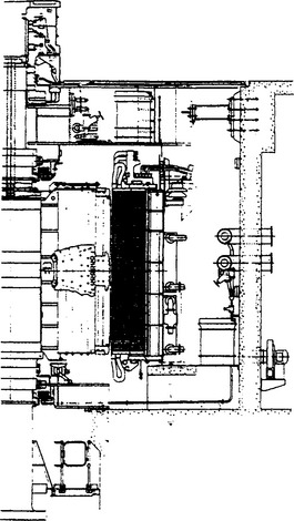
28.17.5.1 Starting26,146
Methods available for starting and run-up of a machine in the pumping mode are: (i) by a direct-coupled auxiliary starting turbine or pony motor, (ii) by back-to-back connection with another machine driven by its own turbine and acting as a generator; (iii) from the power network through a step-down transformer, using the rotor solid pole-shoes or the damper winding as a cage for an ‘induction’ start; and (iv) from the power network through a variable-frequency thyristor converter controlled to give an output over the range of a few hertz up to normal system frequency. In (iii) the pole-shoes or damping windings must be designed to carry the induced currents without excessive rise in temperature. In (iv) the machine moves from rest by induction torque, but at a low frequency it synchronises with the converter and thereafter remains in synchronism up to normal frequency, to be then synchronised with the power network. The starting equipment is expensive, but run-up is more readily supervised, and the damping cage (or pole-shoe) design is not constrained. The method is preferred for large units.
28.18 Salient-pole generators other than hydrogenerators
These are made for synchronous speeds ranging from less than 100 rev/min to 1500 rev/min for 50 Hz and 1800 rev/min for 60 Hz supplies: hence they have from 4 to more than 72 poles. Small 2-pole generators are also made in large numbers. The outputs for salient pole generators range from a few kilovolt-amperes up to about 60 MVA. Prime movers range from internal combustion engines burning petrol, gas (either natural gas or methane obtained from land-fill sites or biomass schemes) or diesel fuel and steam or gas turbines. Direct drive by an internal combustion engine is practicable over the whole range, though at 1500 and 1800 rev/min the output is limited by the maximum engine available power of about 5 MW. Typical ratings for low-speed two-stroke diesel sets are 15–60 MVA at 150–100 rev/min. Diesels, often four-stroke, in the speed range 428–1200 rev/min (14–6 poles) are particularly common, with outputs of say 10–45 MW. Four-pole generators with outputs up to about 60 MVA are driven via a suitable gearbox by high speed (up to 15 000 rev/min) steam or gas turbines.
28.18.1 Applications
Salient-pole generators are used both for stand-by applications and to continuously supply power. They can therefore be connected to public power systems, incorporated in marine installations (ships and oil rigs) or in a great variety of industrial plants. Where a public system requires unit ratings up to about 40 MVA, high speed, medium speed or low speed diesel sets can be installed more cheaply and more quickly than a gas or steam turbine set with its boiler and auxiliaries. The internal combustion engine set can deliver full load within a few minutes of starting, which can be done remotely if necessary; it will respond rapidly to changing load demand, and will have better efficiency at part load than the turbine. The slow two-stroke diesel is particularly suitable for the larger outputs (15–60 MVA), running economically on low grade fuel and with low maintenance costs. The recent focus of attention on emissions has had a marked effect on the choice of type of i.c. engine to be used. Engines burning gas are able to achieve lower level emissions of nitrous and sulphur oxides and are therefore proving very popular for new installations. In contrast, achieving acceptable levels of emissions with 2 stroke diesel engines burning low grade fuel is more difficult and costly.
Combined cycle installations are being increasingly used to attain higher thermal efficiency. Exhaust heat from a gas turbine that drives one generator is used to supply steam to a turbine that drives another. The turbines are high speed, geared down to, usually, the four-pole speed. For outputs greater than the gearbox limit of about 60 MW, two-pole cylindrical rotor generators are directly coupled to the turbines.
For marine applications, high-speed or medium-speed generators are used. These can either be driven by dedicated diesel engines, shaft driven from the engine used for propulsion or, in larger installations by gas turbines.
For ship propulsion, medium-speed diesel or gas turbine driven generators supply d.c. through rectifiers, or variable frequency a.c. to motors coupled to the propellers. The domestic load may be supplied from the same generators, but often separate generators are used—this has the advantage of isolating the domestic supply from the converter harmonics.
Oil rigs can either use internal combustion engine-driven generator sets or gas-turbine-driven generators for their power depending on their size. The generators are required to supply the large drilling motors and mud-pump motors, and the domestic supply. The number, rating and reactances of the generators are chosen to avoid excessive voltage dip when a large motor drive is started, so that other loads are not badly affected. Rated outputs can be around 15 MW where gear-driven generators running at 1800 rev/min would be used or up to 25 MW directly coupled to the power turbine at 3600 rev/min.
Industrial power stations commonly use steam turbines if there is need for process steam, which is delivered through a back-pressure or pass-out turbine; or if waste heat is available to raise steam for generating electricity.
Gas and diesel engines are often used, alone or in combined cycle installations. Gas turbines are expensive to run, and are used only if rapid response to load is essential, or the fuel is locally not so expensive, e.g. in an oil refinery.
28.18.2 Construction
The rotor construction for these salient pole machines is determined by the rating of the unit and its peripheral speed. High-speed rotors with four or six poles and ratings up to about 30 MW can have integral poles which are made up of a series of laminations. These can be punched from sheet material using a die or a nibbling type press; alternatively, they can be manufactured using a laser cutting machine. The thickness of punchings is normally limited to less than 3 mm if one of these processes is used, which has the advantage of limiting the pole-shoe losses. Thicker plates up to 100 mm thick can also be used, in which case the pole profile is cut using a numerically controlled flame cutting machine. With this type of construction, due consideration must then be given to the extra surface losses which will occur in the pole-shoes.
For larger machines, i.e. above 30 MW, with bigger diameter rotors, the peripheral speeds will result in rotational stresses in excess of the safe limits for the laminated type of rotor materials. In this case, forged solid rotors with pole pieces integral with the shaft are used. Solid forged pole-shoes are secured by high tensile strength bolts after the coils have been put on.
For the lower peripheral speeds associated with multipole rotors, separate laminated pole pieces may be secured by dovetails or T heads in slots in the square or hexagonal middle portion of the forged shaft. Alternatively, the laminated poles may be bolted or dovetailed to the wide cylindrical rim of a flywheel on the shaft; or they can be fixed by dovetails or T-head slots in a laminated rim.
The laminated-pole construction is cheaper than a forged rotor, and reduces the cost of the stator winding too, because fewer, wider, stator slots can be used with acceptably low eddy current losses in the pole faces.
Generators may have one or two bearings. Many diesel driven generators have only an outboard bearing, the driving end of the shaft being solidly coupled to the engine crankshaft flange. This shortens the set and saves the cost of a drive end bearing and the flexible coupling. It also allows the generator to be partly supported on a Society of Automobile Engineers (SAE) flange on the engine crankcase. The crankshaft bearing must carry half the weight of the generator rotor. A gearbox bearing can rarely do this, so gear-driven generators normally have two bearings.
The generator may be supported on sole plates grouted into the foundations, or may be bolted directly to the engine base plate, where this has been designed for the purpose. If transport and site lifting facilities permit, the generator can be delivered complete on its own bed plate; this is to be preferred as it saves erection time on site.
Often it is desirable to limit the vibration transmitted to the foundations, especially when the driver is a diesel engine. A common method is to put flexible mountings beneath the combined bed plate. These need to be chosen, or tuned, to isolate the vibration and not to permit resonance at any of the disturbing frequencies.
Class F insulation is always used on high voltage stator and some rotor windings, although class B temperature limits are often specified to extend the life of the machine and give some margin for an overload capability. Class H systems are common on low voltage generators and also on some medium voltage machines. Often class F temperature rises will still be specified even for machines with class H insulation systems in order to achieve an extended life.
Stator coils are usually of the pulled diamond type (see Section 28.4.1). Rotor coils are generally similar to those of hydrogenerators, but as they are smaller they are more often of the wound on edge construction using rectangular strip copper rather than fabricated. Where the rotor has integral poles, the field copper is wound directly onto the pole pieces by rotating the complete rotor or the laminated rotor core-pack about its longitudinal axis.
28.18.3 Ventilation and cooling
These generators are always air-cooled. If an adequate supply of clean air is available, open ventilation with an appropriate class of protection is used. If the air is only slightly dirty, it may be ducted to and from the machine, with filters on the inlet side. In a short machine the air is drawn through from one end to the other by a single centrifugal shaft-mounted fan. Longer machines have radial ducts in the stator core; the air enters the stator bore at both ends and is expelled radially through the ducts to the back of the core. In this case, shaft mounted axial-flow fans are used to drive the air through the machine.
In dirtier surroundings a totally enclosed machine is used. The primary (internal) air is circulated by shaft fans through an air to air heat exchanger (c.a.c.a. arrangement). The secondary (external, ambient air) is driven through the heat exchanger by one or more separate motor driven fans. Alternatively a water-cooled heat exchanger is used (c.a.c.w. arrangement). The materials used in the heat exchanger must be chosen to suit the quality of the water, e.g. tubes of aluminium brass or cupro-nickel if the water is salty. The limits of temperature rise may be adjusted in accordance with the maximum temperature of the secondary coolant. (see Section 28.5.)
28.18.4 Particular design requirements
28.18.4.1 Machines for operation in hazardous atmospheres
As a result of a vast increase in power generation for the oil industry, and a few catastrophic accidents, generators are required to be designed to operate safely in potentially hazardous atmospheres. BS EN 60079-10:1996 defines the different levels of hazard. Generators, especially when driven by gas turbines, are considered to operate in a zone-2 area. They must be designed and made to prevent any gas that is present being ignited, and compliance with the requirements must be certified by a type-N certificate granted by one of the nominated inspecting authorities. The requirements are specified in BS 5000-16:1997. They are many and complicated, but the major ones can be summarised thus. For a particular group of gases, the surface temperatures of all bare live parts must not exceed an ignition temperature defined for that group. Mechanical clearances on fans, including separate motor-driven fan units, must be greater than usual to prevent any contact between the stationary and the rotating parts, to avoid sparking or excessive local temperatures. Auxiliary electrical devices, including terminals, heaters, fan motors, etc., must all be of certified origin, with certificates of conformity to demonstrate that they comply with the requirements.
28.18.4.2 Reactances
Xd, X′d and X′′d are those that have most influence on the design and the operation of the generator. A maximum Xd or minimum short-circuit ratio is usually specified. A minimum value of X′d or a maximum X′d are either specified or implied by specifying the permissible fault megavolt-amperes or the grade of voltage regulation required. For example, BS 4999-140:1987 specifies voltage regulation grades in terms of
(1) accuracy of voltage control under steady load;
(2) voltage dip when specified loads are suddenly applied; and
This performance is with the automatic voltage regulator in control of course, but implies lower X′d to achieve the smaller voltage dips and rises. As implied in, Section 28.6.1.4 it becomes expensive to specify a closer grade of voltage regulation than is really needed. The grade may be unattainable if X″d is high to limit the fault megavolt-amperes.
28.18.4.3 Generators driven by internal combustion engines
ISO standard 8528 (equivalent to BS 7698:1993) entitled ‘Reciprocating internal combustion engine driven a.c. generating sets’ is applicable to generators used in these applications. Most of the standard is concerned with the engines, controls, etc., but Parts 3,5 and 9 contain requirements for the generator, including definitions and limit values of parameters to do with voltage control.
The mechanical design of such sets must consider the transverse vibration and critical speeds of the shaft assembly, and also the possible torsional modes. BS 5000-3:1980 and ISO 8528 place the responsibility for seeing that the torsional behaviour is investigated with the supplier of the set, assisted by the makers of the engine and the generator. Some cyclic irregularity of the generator speed is inevitable: the rotor inertia may be enough to keep it acceptably small, but an extra flywheel may be needed.
Cyclic irregularity of torque will occur at frequencies determined by the number of firing impulses per second. In low-speed sets (100–150 rev/min) one of these harmonic frequencies may lie near to 10 Hz, and around this frequency the eye is very sensitive to light flicker caused by fluctuation of voltage as small as 0.5%. The fluctuation may affect the operation of electronic equipment, mains ripple control systems, etc. If it is impracticable, or too expensive, to reduce the speed fluctuation by adding more inertia, the voltage swing can be reduced with a high response excitation system, phase-controlled to swing the generator flux in opposition to the speed.
If the cylinder torques are not all equal, there will also be torque fluctuations at rotational frequency or low multiples of it, i.e. in the frequency range 1 1/2 to 4 1/4 Hz. For most sets the natural frequency of electromechanical oscillation relative to the power system lies in this range. The resonant, or near-resonant, swings of load angle, power, voltage, etc., may nevertheless be tolerably small if the generator has a sufficiently effective damper winding.
28.19 Synchronous compensators
Synchronous compensators are synchronous motors running without mechanical load; they are used to generate or absorb reactive power, in order to control the voltage of a power system. Hence they are usually installed near a load, or part way down a long transmission line to support the voltage at the intermediate point.
At times of heavy load, compensators run overexcited to supply the magnetising power demanded by the load (transformers and induction motors) or the inductive I2X losses of the line. At light load they must run underexcited to take reactive power from the line to offset the capacitive line-charging current and so avoid excessive voltage rise. In many h.v. systems (200 kV and above), the line capacitive power exceeds the load magnetising power, even at times of heavy load.
Static inductors and capacitors, switched to suit the system conditions, can be used for the same purpose, but the synchronous compensator has the advantage of providing continuously variable control, and with thyristor excitation it can have a response fast enough for many contingencies.
Thyristor-controlled static compensators give rapid and continuously variable control, but require filters to limit harmonic generation in the power system. Lower maintenance and running costs give them an advantage over rotating machines in most new installations.
Synchronous compensators up to 300 MVAR are in service. Air cooling has been used up to ratings of 40 MVAR, but hydrogen cooling is now normal to reduce the size and the light-load losses, the latter by reducing windage. As the shaft-end need not emerge from the hydrogen-tight casing, no shaft seals are needed. Losses at full load (overexcited) are in the range 0.01–0.016 MW per MVAR of rating.
The underexcited capability is usually about half the overexcited rating; for this a short-circuit ratio of about 0.75 is desirable, to ensure that at the underexcited capability the rotor has sufficient positive excitation to maintain stability. A short-circuit ratio of 1.3–1.5 will provide an underexcited capability level equal to the overexcited level, but the machine is larger and has higher losses than the design with the lower short-circuit ratio. Water cooling has been used for stator and/or rotor windings at ratings of 200 MVAR or more.
The compensator may be run up to speed as an induction motor through a step-down transformer, by means of a direct-coupled pony motor, or by using a variable-frequency inverter.
28.20 Induction generators157–164
If an induction motor is driven above synchronous speed it will deliver power to the system, with a slip of about −0.05 at full load. It has the advantage of simple construction, and needs no excitation, speed governing, or synchronising. This makes it cheaper than a synchronous machine and operationally more convenient, e.g. for unattended hydrostations or wind-driven generators. The disadvantage is that it must draw from the power system magnetising power of 0.5–0.75 of its rated active power output, and this has limited the size to about 5 MW.
Research in the USA has shown that, by using static var compensators to supply the reactive power, it should be practicable to run induction generators of a few hundred megawatts output either in parallel with synchronous generators or even as a separate supply system. Speed control would then be essential to fix the frequency of the separate system.
Connection to the power network can be made merely by closing the breaker when the machine is up to synchronous speed. To reduce the current surge in large machines, the machine can be allowed to build up to normal voltage by first connecting a capacitor and then synchronising in the usual way. By suitable design of the machine and the static compensator, efficiency and stability can be comparable to those of a synchronous machine.
The most suitable locations appear to be where transmission by h.v. cable is required, for the cable capacitance will contribute to the reactive-power requirement, and at points in the system where substantial var support is installed anyway, the generator being run when active power is also required.
To maintain stability following system faults requires considerable reactive-power capacity beyond that needed for steady full-load operation. Where the system is strong enough, however, this is not too costly, and the total cost of the induction generator installation can be less than that of a synchronous unit.
28.21 Standards
A selection of standards relevant to generators published by ANSI, BSI, Cenelec, IEC, IEEE and NEMA is listed below. Revisions are made every few years, so care must be taken to use the most recent issue, or an earlier one if that is relevant. Member countries of the European Economic Community are required not to have national standards that conflict with Cenelec Euronorms or Harmonised Documents. Some of these documents are technically equivalent to, or closely similar to, IEC standards that were adopted as the bases for harmonisation. British Standards are technically equivalent to relevant Cenelec documents, or to IEC standards if a corresponding Cenelec standard has not been published. BS EN 60034 parts 1 to 22 are numbered consistently with IEC 60034-1 to 60034-22. For a full comparison, see BS 4999: Part 0. The parts of BS 5000 relate to machines of particular types or for particular applications, and call for parts of BS 4999 where appropriate.
Copies of standards can be obtained through the addresses shown for the standards authorities in Chapter 49; BSI, ANSI and IEEE documents are available directly from, respectively:
BSI Sales, Linford Wood, Milton Keynes MK14 6LE, UK
ANSI, II West 42nd Street, New York, NY 10036, USA
NEMA 1300 North 17th Street, Suite 1847, Rosslyn, VA 22209, USA
IEEE Service Centre, 445 Hoes Lane, Piscataway, NY 08854, USA
Acknowledgements
Acknowledgements are given to the following.
IEEE for permission to reproduce (a) Figure I from reference 19 as Figure 28.32, and (b) portions of Tables 1 and 2 from reference 22 as Table 28.2.
BSI for information from BS EN 60034-1 used in Sections 28.4.4, 28.5 and 28.14; from BS EN 60034-3 used in Section 28.5 and from BS 4999: Part 0 used in Section 28.21.
ANSI for information from Standards C50: Parts 10–15 used in Sections 28.4.4 and 28.5
IEEE for information from standard Standard 421.1 used in Section 28.14.
Copyright in these publications is held by the organisations listed.
The author expresses his thanks to the Directors of Newage International Ltd for their permission to carry out the necessary editing and updating of this chapter.
His thanks are also given to Mr Albert Hunt and his many other ex-colleagues at ALSTOM for the assistance given at the time of preparation of the text contained in the previous edition of this book, from which much of the current material is derived. In particular, Messrs. G. K. Ridley and I. McShane in connection with Sections 28.17 and 28.18, Mr H. S. McNaughton (Section 28.4); Dr G. K. M. Khan and Dr T. W. Preston for the preparation of Figures 28.1 and 28.6; Mr N. C. W. Grocott, Prof. A. B. J. Reece and Dr R. D. M. Whitelaw for information and discussion on many subjects; and Mr P. H. Conceicao and Dr R. A. Hore for information and discussion.
Books (arranged in reverse order of publication date)
1. Chalmers, B.J., Williamson, A. C., A.c. Machines Electromagnetics and Design. Brussels: Research Studies Press; 1991.
2. Ames, R.L. A.c. Generators Design and Application. Taunton: Research Studies Press; 1990.
3. Smith, J.R. Response Analysis of a.c. Electrical Machines Computer Models and Simulation. Taunton: Research Studies Press; 1989.
4. Tavner, P.J., Penman, J. Condition Monitoring of Electrical Machines. Taunton: Research Studies Press; 1989.
5. , Electrical Motor Handbook. Chalmers B.J., Taunton: Butterworth, 1988.
6. Say, M.G. Alternating Current Machines, 5th edn. London: Pitman; 1983.
7. Fitzgerald, A.E., Kingsley, C., UMANS, S.D. Electric Machinery, 4th edition. London: McGraw Hill; 1983.
8. (Paperback edition from University Microfilm International via White Swan House, High St, Godstone, Surrey, England) Walker, J.H. Large Synchronous Machines Design, Manufacture and Operation. New York: Oxford Scientific Publications, Clarendon Press; 1981.
9. Sarma, M.S. Synchronous Machines Their Theory, Stability and Excitation Systems. Oxford: Gordon and Breach; 1987.
10. Chap 7, Synchronous machines Guile, A.E., Patersons, W. Electric Power Systems. New York and London: Pergamon Press; 1977.
11. (translated from the Russian) Kostenko, M., Petrovsky, L., Electrical Machines. A C machines, 3rd edition. Oxford: Mir Publishers, 1977.
12. Adkins, B., Harley, R.G. The General Theory of A.C. Machines. Moscow: Chapman and Hall; 1975.
13. Say, M.G. Introduction to the unified theory of electromagnetic machines. London: Pitman; 1971.
14. British Electricity International. Modern Power Station Practice, 12 vols Turbines, Generators and Associated Plant, 3rd edition. London: Pergamon; 1992.
15. , Hydroelectric Engineering Practice. Brown J.G., Oxford: Blackie and Son, 1964. Chapters 7–9
16. Jain, G.C. Design, Operation and Testing of Synchronous Machines. Glasgow: Asia Publishing House; 1959.
17. Lewis, W.A. The Principles of Synchronous Machines. London: Illinois Institute of Technology; 1959.
18. Say, M.G. Performance and Design of a c Machines. Chicago, IL: Pitman; 1958.
19. Kimbark, E.W. Power System Stability. In Synchronous Machines. London: Chapman and Hall; 1956.
20. Langsdorf, A.F. Theory of a c machinery, 2nd edition. London: McGraw Hill; 1955.
21. Concordia, C. Synchronous Machines Theory and Performance. New York: General Electric Co; 1951.
22. Liwschitz-Garik, M. Winding a c Machines. Schenectady, NY: McMillan van Nostrand; 1950.
23. Liwschitz-Garik, M., Whipple, C.C. Electrical machinery. In A.C. Machines. London: van Nostrand; 1946.
24. Various Authors. Transmission and distribution handbook. New York: Westinghouse; 1946.
25. Hammons, T.J., Geddes, A.G. Assessment of alternative energy sources for generation of electricity in the UK following privatization of the electricity supply industry. IEEE T En. Conv.. December 1990;5(No 4):609–615.
26. Foster, E.N., Parker, F.J. ‘Hydroelectric machines’. IEE Proc., Part C. April 1986;133(No 3):126–136.
27. Fritsch, T.A., ‘Recent trends in large thermal and hydroelectric power production generators’. Trans The South African Inst of Elec Eng, November. 1978:318–334.
28. Seoni, R.M. ‘Review of trends of large hydro-electric generating equipment’. Proc. IEE. 123(No 10R), 1976.
29. Vickers, V.J. ‘Recent trends in turbogenerators’. Proc. IEE. November 1974;121(No 11R):1273–1306.
30. Anscombe, L.D. A c generators for hydro-electric stations’. Proc. IEE. July 1963;110(No 7):1223–1234.
Flux and e.m.f. waveforms, a.c. windings
31. Liwschitz-Garik, M. Winding a c Machines. Pittsburgh, PA: McMillan van Nostrand, 1950. translated from the Russian. Kostenko M., Petrovsky L., Electrical Machines. A.C. machines, 3rd edition. London: Mir Publishers, 1977. Chalmers B.J., Williamson A.C., A.C. Machines Electromagnetics and Design. Moscow: Research Studies Press, 1991. Liwschitz-Garik M., Whipple C.C., Electrical Machinery. A.C. Machines. Taunton: van Nostrand, 1946. Say M.G., Alternating Current Machines, 5th edn. New York: Pitman, 1983. (Paperback edn from University Microfilm International via White Swan House, High St, Godstone, Surrey, England). Walker J.H., Large Synchronous Machines Design, Manufacture and Operation. London: Oxford Scientific Publications, Clarendon Press; 1981.
32. Walker, J.H. ‘Parasitic losses in synchronous machine damper windings’. J. IEE, P II. 1947;94:13–25.
33. ‘A.C. tooth ripple losses in slotted laminated machines with amortisseur windings’. IEEE PAS. May 1982;101(No 5):1122–1128.
34. Stephen, D.D. ‘Evaluation of characteristics of a c stator windings’. GEC. J. Sci. Technol. 1973;40(No 1):25–32.
35. Burbidge, R.F. ‘A rapid method of analysing the m m f wave of a single or polyphase winding’. IEE Monograph No 2805. (January):1958.
36. Liwschitz-Garik, M. ‘Distribution factors and pitch factors of the harmonics of a fractional-slot winding’. Trans AIEE. 1943;62(October):664–666.
37. (5 refs) CHALMERS, B.J. ‘A.C. machine windings with reduced harmonic content’. Proc. IEE. November 1964;111(No 11):1859–1863.
38. paper No 26785 Walker, J.H., Kerruish, N. ‘Design of fractional slot windings’. (12 refs). Proc. IEE. 1958;105(August):428–440.
39. Liwschitz-Garik, M. ‘Harmonics of the salient pole machine and their effects Part 1 MMF harmonics produced by armature and damper windings’. Trans. AIEE, PAS. 1956;75:35–39.
40. Stromberg, T. ‘Alternator voltage waveshape with particular reference to the higher harmonicss’. ASEA J.. 1947:139–148.
41. Calvert, J.F. ‘Amplitudes of magneto-motive force harmonics for fractional-slot windings’. Trans. AIEE. 1938;57:777–785.
42. Angst, G., Oldenkamp, J.L. ‘Third harmonic voltage generation in salient pole synchronous machines’. Trans. AIEE PAS. (June):1956.
43. Paper No 777 Walker, J.H., ‘Slot ripples in alternator e m f waves’. 97 Part II, 45–46 (1950). Proc. IEE, Part II. 1949;96:81–92. 97 Part II, 45–46 (1950).
44. Wieseman, R.W., ‘Graphical determination of magnetic fields’. Trans. AIEE, February. 1927:141–154.
45. (4 refs) Ginsberg, D., Jokl, A.L., Blum, L.M., ‘Calculation of no load waveshape of salient-pole AC generators’. Trans. AIEE PAS, October. 1953:974–980.
46. (6 refs) Ginsberg, G.D., Jokl, A.L., ‘Voltage harmonics of salient-pole generators under balanced 3-phase loads-I’. Trans. AIEE, February 1960. 1959:1573–1580.
47. Ginsburg, G.D., Jokl, A.L., ‘Voltage harmonics of salient-pole generators under balanced 3-phase loads-II’. Trans-AIEE PAS, August. 1960:560–565. (7 refs)
Coils and insulation Coil construction, materials and windings
48. , Electrical Motor Handbook. Chalmers B.J., Oxford: Butterworth, 1988.
49. Liwschitz-Garik, M. Winding a c Machines. London: McMillan van Nostrand; 1950.
50. translated from the Russian Kostenko, M., Petrovsky, L., Electrical Machines. A.C. machines, 3rd edn. London: Mir Publishers, 1977.
51. Bennington And Brenner. Transpositions in T.G. coilsides-short circuit at ends. IEEE PAS. November-December 1970;89(No 8):1915–1921.
52. ‘Reduction of armature copper losses’. Trans. AIEE. 1927;46(Febuary):101–111.
53. Mains, A.J., Mcnaughton, H.S. ‘Design and manufacture of a c stator windings for hydro-generators a review of the 18 kV generator-motor units at Dinorwig power station’. In Proc. 6 BEAMA Intl. Electrical Insulation Conf.. Moscow: British Electrical and Allied Manufacturers Association; 1990.
54. (Presented at 5th BEAM A Intl Conf on Electrical Insulation, May 1986) Neal, J.E., Whitman, A.G., ‘The role of backing materials in mica-paper based insulation for h v rotating machines’. IEEE Elec Insulation Magazine, 2, No 4. July 1986:30–34.
55. Smith, G.F. ‘Mica Film’. Proc 5th BEAMA Conf.. 1986.
56. Schuler, R., ‘H v rotating machines turn insulation for stator windings with form wound coils’. Proc 2nd IEEE Intl Conf on properties and applications of Dielectric materials, 1988.
57. Nurse, J.A., Kennedy, A.G. ‘Global vacuum impregnation of large high voltage stator windings’. In Proc of 6 th BEAM A Intl Conf on Electrical Insulation. Beijing: British Electrical and Allied Manufacturers Association; 1990.
58. Nurse, J.A. ‘Resivac-an insulation system with extended life. GEC. Rev.. 1986;2(No 2):111–116.
59. Hutter, W., Liptak, G., Schuler, R. ‘Micadur-compact insulation system for rotating h v machines up to medium ratings-behaviour under extreme operating conditions’. Brown-Boveri Rev.. 1984;6/7:294–298.
60. Mcnaughton, H.S., Nurse, J.A. ‘Vacuum-pressure impregnation and resin-rich insulation systems for high voltage industrial machines-a comparison’. In IEE Intl Conf on Electrical Machines-Design and Application. London: IEE; 1982.
61. Jonsson, K. ‘Micapact II coils for h v rotating machines’. ASEA J.. 1981;54(No 2):27–35.
Insulation testing and evaluation
62. IEEE. ‘Recommended practice for voltage-endurance testing of form wound bars and coils’. IEEE Standard. 1043, 1989.
63. IEEE. ‘Proposed Test procedure for evaluation of systems of insulating materials for a c electric machinery employing form wound pre-insulated stator coils’. In IEEE Standard 275. London: these two were presented at the 1990 IEEE International Symposium on Electrical Insulation; 1990.
64. IEEE. ‘Recommended practice for insulation testing of large a c rotating machinery with high direct voltage’. ANSI/IEEE Standard 95 (67 refs). 1977.
65. Reynolds, P.H., Leszczyswki, S.A. ‘Direct current insulation analysis-a new and better test method’. IEEE PAS 104. 1985;7:1746–1749.
66. Meyer, H., Wichmann, A. ‘Experience and practice with standardised acceptance test procedures for windings of rotating machinery’. Proc 16th Electrical/Electronics Insulation Conference, Chicago. 1983;IL:146–151.
67. Brancato, E.L., ‘New diagnostics for rotating machinery (an EPRI report)’. IEEE Insulation Mag, January-February. 1989:40–41.
68. Yeshida, H., Umemoto, K. ‘Insulation diagnostics for rotating machines. IEEE Trans on Elec Insulation. 1986;E1(21):1021–1025.
69. Simons, J.S. ‘Diagnostic testing of h v machine insulation’. Proc IEE, Part B. May 1980;127(No 3):139–154.
70. Wichman, A. ‘Two decades of experience and progress in epoxy-mica insulation systems for large rotating machines’. IEEE Trans PAS. 1982;102:74–82.
71. CH 2726-8 Dacier, J., Goffaux, R. ‘Contribution to the overall and local characterisation of the condition of electrical ageing of hv insulation in large rotating machines’. Proc 3rd Intl Conf on Conduction and Breakdown in Solid Dielectrics, IEEE Catalogue No 89. (July):1989.
72. Kako, Y. ‘An analysis of multifactor ageing of mica-epoxy insulation systems by the infinite sequential stress method’. IEEE Trans on Elec Ins. 1987;22:69–76.
73. see also 45-52 Simoni, L. ‘An analysis of combined stress degradation of rotating machine insulation’. IEEE Trans on Elec Ins.. 1984;19:364–367.
74. Rengarajan, S., ‘Accelerated ageing of h v machine insulation under combined thermal and electrical stress’. Annual report, Conf on Elec Ins and Dielectric Phenomena. IEEE Trans on Elec Ins.. 1983:129–136.
75. Kim, Y.J., Nelson, J.K. ‘Voltage dependence of corona signature from defect stator bar insulation during ageing’. Conf report IEEE Trans on Elec Ins.. 1986:502–507.
76. Various Authors Five papers on testing and ageing of insulation CIGRE conference on large h v systems 1976, Paper Nos 15-00, 15-03, 15-05, 15-06 an
77. Wichmann, A. ‘Accelerated voltage endurance testing of micaceous insulation systems for large turbo-generators under combined stresses’. IEEE PAS.. 1977;96:255–260.
78. Wichmann, A., Grunewald, P. ‘Statistical evaluation of accelerated voltage endurance tests on mica insulation for rotating electrical machines’. IEEE Trans on Elec Ins.. 1990;25:319–323.
79. Pierrat, L., Steinle, J.L. ‘On load methods for dielectric diagnosis of large rotating machines’. CIGRE Paper. 11-14, 1988.
80. Krecke, M., Goffaux, R. ‘Attempt at estimating the residual life of the h v insulation of a.c. rotating machines’. CIGRE Paper. 11-12, 1988.
81. Goffaux, R. ‘A novel electrical methodology of diagnosis for the h v insulation of a c generators’. CIGRE Paper. 11-12, 1986.
82. Jonsson, K., Rodolfsson, D. ‘Diagnostic test of insulation A test package to determine the condition of the generator stator winding insulation’. CIGRE Paper. 11-11, 1986.
Determination of machine parameters
83. See Standards in section 28 21 IEC 34-4, BS 4999 Part 104, IEEE 115 and 115A
84. Kilgore, L.A., ‘Calculation of synchronous machine constants-reactances and time constants’. Trans. AIEE, December. 1931:1201–1214.
85. Chapter 5 Kostenko, M., Petrovsky, L., Electrical Machines. (translated from the Russian). A C machines, 3rd edition. Mir Publishers, 1977.
86. Lawrenson, P. ‘Calculation of machine endwindmg inductances with special reference to turbogenerators’. Proc. IEE. 117(No 6), 1970.
87. Mello, De. Derivation of synchronous machine stability parameters from pole slipping conditions. IEEE T-PAS. September 1982;101(No 9):3394–3402.
88. Balda, J.C. ‘Measurement of synchronous machine parameters by a modified frequency response method’. IEEE T-EC.. December 1981;2(No 4):646–651.
89. (19 refs) Jack, A.G., Bedford, T.J. ‘A study of the frequency response of turbine generators with particular reference to Nanticoke’. IEEE T-EC.. September 1987;2(No 3):495–505.
90. (28 refs) Kamura, I., Viarouge, P., Dickinson, J. ‘Direct estimation of the generalised equivalent circuits of synchronous machines from short-circuit oscillographs’. Proc IEE, Part C. November 1990;137-6:445–452.
91. Canay, M. ‘Identification and determination of synchronous machine parameters’. Brown-Boven Rev.. 1984;6/7:299–304.
Turbogenerators Design and construction
92. Creek, F.R.L. ‘The design of 985 MW 2 pole 3000rpm turbine generators for Day a Bay nuclear P S’. GEC Rev.. 1988;4(No 3):176–186.
93. Marlow, B.A. ‘The mechanical design of large turbo-generators 51st Parsons memorial lecture’. Proc. Inst. Mech. Eng.. 200, 1986.
94. Guillard, J.M., Damiron, R., ‘300 MW Modular design generators’. Alsthom Rev., No 7. 1987:19–30.
95. Hasse, H., Largiader, H.G. ‘Air cooled turbine generators in the 200 MVA class’. Brown-Boveri Rev.. (No 3):1986.
96. Hasse, H, Largiader, H.G. ‘Design and operation on test bed of a 200 MVA air cooled turbine generator’. Proc. CIGRE.. 11-09, 1984.
97. (In English) Voronowski, G.P. ‘Standard structural design solutions for turbogenerators’. Elektro teknika. 46(No 1), 1975.
98. Glebov, I.A., et al. ‘A 1200 MW 3000 rpm turbogenerator’. Elektrotektronika. 49(No 3), 1978.
99. Fedorov, V.F., et al. ‘fully water cooled 800 MW 3000 rpm turbogenerator’. Proc. CIGRE. 11-11, 1984.
100. Ambrecht, D., Erger, H. ‘Integrated endwinding ring support for water-cooled stator winding’. IEEE PAS. 102(No 4), April 1983.
101. KHAN, G.K.M., et al. ‘Calculating electromagnetic forces on endwmdings of large turbogenerators’. IEEE T-EC. December 1989:661–670.
102. (38 refs) Mecrow, BC, Jack, AG, Cross, CS, ‘Electromagnetic design of t g stator end regions’. Proc IEE 136-C, No 6. November 1989:361–372.
103. Singleton, et al. ‘Axial magnetic flux in synchronous machines’. IEEE PAS. March 1981;100-3:1226–1233.
104. (23 refs) Kahn, G.K.M., et al. ‘An integrated approach to the calculation of losses and temperature in the end region of large turbogenerators’. IEEE T-EC. March 1990;5-1:183–194.
105. Coulson, et al. ‘Transient negative sequence capability of turbine generators a rational assessment’. CIGRE Proc. 11-02, 1980.
106. CIGRE Study Committee. ‘CIGRE repot-A summary of replies to a questionnaire on the properties and design of t g rotor endnngs’. Electra, 80;January 1982. Electra. 17(March), 1988.
107. Pub No EL 3209 EPRI. ‘Retaining rings for electric generators’. Workshop Proceedings, August 1983.
108. VSG Publication on 18Mn 18Cr retaining rings, from VSG, Altendorferstrasse 104, D-4300, Essen, Post 10225, Germany
109. , ‘Improved steels for non-magnetic generator endnngs’. September. Conf Proc Materials Development in Turbo-machinery Design. Churchill College Cambridge: Moscow, 1988:12–14. available from Institute of Metals
Operation, monitoring and testing
110. IEEE. ‘Guide for operation and maintenance turbine type generators’. refs. IEEE Standard 67-1990. 1990:88.
111. Mamikoniants, L.G. for Study Committee 11, ‘Draft guidelines on some of the synchronous generator abnormal operation conditions’. Proc. CIGRE. 11-13, 1980.
112. Huttner, H., et al. ‘Some aspects on diagnosis methods and operational monitoring for large ac generators’. Proc. CIGRE. 11-01, 1986.
113. Sandhu, S., et al. ‘Diagnostic methods for testing the electrical and mechanical integrity of stator end-windings of large turbogenerators’. Proc. CIGRE. 11-03, 1986.
114. ‘Investigations into the mechanical behaviour of turbogenerator stator windings during faults’. Proc. CIGRE. 11-14, 1980.
115. Jackson, R.J., et al. ‘Generator rotor monitoring in the UK’. Proc. CIGRE. 11-04, 1986.
116. Granger, B., Lehuen, C. In situ ultrasonic inspection of t g rotor endbells’. Proc. CIGRE. 11-10, 1986.
117. Verma, S.P., et al. ‘The problems and failures caused by shaft potentials and bearing-currents in turbogenerators methods of prevention’. Proc. CIGRE. 11-10, 1980.
118. Candelori, C., et al. ‘Shaft voltages in large t g with static excitation Experimental investigations and protective devices’. Proc. CIGRE. 11-04, 1988.
119. Joho, R., et al. ‘Shaft voltages in turbosets a new grounding design to improve reliability of the bearings’. Proc. CIGRE. 11-10, 1988.
120. Heard, J.G. ‘Summary report on large turbine generator maintenance practices’. CIGRE Electra. 11(March), 1988.
121. Emery, F.T., Harrold, R.T. ‘On line incipient arc detection in large t g stator windings’. T-PAS. 1980;99-6:2232–2238. November/December
122. Schuler, R.H., Liptak, G. ‘A new method for high-voltage testing of field windings (interturn insulation)’. CIGRE Proc.. 11-04, 1980.
123. ‘Diagonal flow ventilation of gap pickup rotors’. IEEE PAS. (Febuary):1963.
124. Gott, B.E.B., Kaminski, C.A., Shortrand, A.C. ‘Experience and recent development with gas directly cooled rotors for large steam turbine generators’. IEEE PAS. October 1984;103(No 10):2974–2981.
125. Csillag, I.K., ‘Studies in cooling of gap pick up turbine generators with cross flow ventilation’. T-PAS, May/June. 1979:871–882.
126. Grunenwald, J, et al. Rotor water cooling in turbogenerators. Proc. CIGRE. 11-07, 1980.
127. Mang, Y. Twenty-one year development in turbine generators with water-cooled stator and rotor windings. IEEE PAS. 101(No 3), March 1982.
128. Ieee Subsynchronous Resonance Working Group. Comparison of SSR calculations and test results. IEEE T-PWRS. 1989:336–344. Febuary
129. Ieee Subsynchronous Resonance Working Group. Bibliography. T-PAS, 95-1;January/Febuary. 1976:216–218. First Supplement. T-PAS, 98-6;November/December. 1979:1872-1875. ‘Second Supplement’. T-PAS. 1985;104(February):321-332.
130. ‘Torsional interactions between synchronous generators and long transmission lines supersynchronous and subsynchronous resonances’. IEEE T-PWRS.. 1987:17–24. February
131. Lambrecht, D., et al. ‘Evaluation of the torsional impact of accumulated failure combinations on turbine generator shafts as a basis of design guidelines’. Proc Cigre.. 11-06, 1984.
132. Rusche, P.A. TG shaft stresses due to network disturbances a bibliography with extracts’. PAS 99-6. 1980:2146–2152. November/December
133. Dunlop, R.D., et al. ‘Torsional oscillations and fatigue of steam t g shafts caused by system disturbances and switching events’. Proc Cigre.. 11-06, 1980.
134. Cudworth, C.J., Smith, J.R. ‘Steam turbine generator shaft torque transients a comparison of simulated and test results’. Proc. IEE. 1990;137-C(September):327–334.
135. (48 refs) Masrur, M.A., et al. ‘Studies on asynchronous operation of synchronous machines and related shaft torsional stresses’. IEE Proc-C. 1991;138-1(January):47–56.
136. Heathcote, C., Petty, D.J., Smith, R.J. ‘Lifetime capability of turbogenerators to withstand vibration and other cyclic effects’. Proc. CIGRE. 11-09, 1988.
137. Glebov, I.A., et al. ‘Vibratory behaviour study and control of large turbo and hydro-generators’. Proc. CIGRE. 11-11, 1988.
138. ‘615 MVA generators for Grand Coulee electrical and mechanical design features’. PAS.. 1975;94:2015–2022. November/December
139. ‘Large hydro-generators at Grand Coulee 3-design experience’. PAS.. 1983;102:3265–3270. October
140. ‘Pumped storage plants’. PAS. ‘Machine design and performance’. 1980;22:1828–1837.System analysis. 1980:1838-1844. September/October.
141. Various Authors. Bulb type generators ‘St Onge, Rock Island 2’. PAS., 96;Sept/October. 1977:1690–1696. ‘McGilvery, Manitoba’. PAS., 99;May/June. 1980:990-997. ‘St Onge, Columbia River’. ‘Ruelle, Rock Island’. PAS., 101;June. 1982:1313-1321. PAS., 101;March. 1982:639-643. ‘Paine’. PAS.. 1984;103(September):2405-2409.
142. gives operating experience Kermit, P. ‘Design features of the Helms pumped storage project’. IEEE T-EC.. 9-15(March), 1989.
143. Bevc, F.P., Meehan, R.J. ‘Generator-motors for PG and E Helms pumped-storage project’. IEEE PAS.. 1980;99-6(November/December):2021–2030.
144. Hydraulic Generators and Synchronous Compensators’. CIGRE-Proceedings of the Rio de Janeiro Symposium. (November):1983.
145. Various Authors. Special issue on hydroelectric power. IEE Proc-C. (No 3):April 1986.
146. Hlavac, J., Gleich, K. ‘Design and proving tests of generator motors of 121 MVA 136 5 rpm with asynchronous starting’. Proc. CIGRE. 11-03, 1980.
147. Kranz, R.D., for STUDY COMMITTEE 11. Selected aspects of salient pole machines mechanical problems. Proc. CIGRE, 11-15, 1980.
148. Talas, P, et al. ‘On-line monitoring of airgap of hydro-electric generator using optical tnangulation’. IEEE T-EC.. 526–533(December), 1987.
149. ‘Laminated segmental rims’. PAS 95. 1976. July/August ‘Elastic behaviour’. 1976:1045-1053. ‘Design criteria’. 1976:1054-1061.
150. Xu, Shizhang. ‘Magnetic vibration of hydrogenerators stator core due to rotor eccentricity, rotornon-circularity and negative sequence current’. CIGRE Electna. 1983;86(January):77–88.
151. Toom, P.O., et al. ‘Application of precision airgap monitor for analysis of generator problems’. Proc. CIGRE. 11-02, 1986.
152. Paixao, R., et al. ‘Research analysis of the effects of switching operations on hydro units A diagnosis of unit life performance’. Proc. CIGRE. 11-05, 1986.
153. Mistry, D.K., et al, ‘Salient design features of brushless hydro-generators for mini/micro hydroelectric schemes’. Indian Electrical and Electronic Manufacturers’ Association, Bombay (11 pages). Seminar Elroma 88, January, 1988.
154. Smith, J.R., et al. ‘Prediction of forces on the retaining structure hydrogenerators during severe disturbances’. Electric Power Systems Res. (Switzerland). February 1988;14(No 1):1–9.
155. ‘Radial magnetic pull in salient pole machines with eccentric rotors’. IEEE T-EC. 1987;2(No 3):413–439. September
156. Ieee Working Group Report, Hydro generator thermoset insulation systems-premature failures bibliography. T-PAS., July. 1981:3284–3303.
157. (22 refs) Leithead, W.E., et al. ‘The role and objectives of control for wind turbines’. Proc. IEE Pan C. March 1991;38(No 2):135–148.
158. (13 refs) Malik, N.H., Al-Bahrani, A.H. ‘Influence of the terminal capacitor on the performance characteristics of a self-excited induction generator’. IEE Proc-C. March 1990;137(No 2):168–173.
159. Murthy, S.S., et al, ‘Grid connected induction generators driven by mini-hydro or wind turbines operational behaviour’. IEEE 7-En Conv., March. 1990:1–7.
160. (5 refs) Jabri, A.K., Alolah, A.1. ‘Limits on the performance of the 3-phase self excited induction generator’. IEEE T-En Conv.. June, 1990;5(No 2):350–356.
161. De, Mello, et al. ‘Application of induction generator in power systems’. IEEE PAS.. 1982;101-9(September):3385–3393.
162. Demoulias, C.S., et al, ‘Transient behaviour and self-excitation of wind driven induction generator after disconnection from the power grid’. IEEE T-EC., June. 1990:272–278.
163. Woodward, J.L. Induction generators in micro hydro-electric systems. Seminar Elroma 88. 1988. Indian Electrical and Electronic Manufacturers’ Association, Bombay (11 pages) January 1988) Bombay
164. Grantham, C., et al, Steady state and transient analysis of induction generators. Proc. IEE Part B No 2, March. 1989:61–68. (18 refs)
165. , ‘A high initial response brushless excitation system’. IEEE PAS 90, September/October. 1971:2089–2094.
166. Cotzas, G.M., Hesse, H.M., Lane, L.J. ‘Electrical design and steady state performance of Generrex (Trade Mark of GE) excitation system’. T-PAS. 1979;98-6(November/December):2251–2261.
167. Chabot, E., Tran, Thanh Tam. ‘New developments in brushless beanngless integral hydrogen cooled excitation generator for 3000 rpm unit’. Proc. CIGRE. 11-13, 1984.
168. Hurley, J.D., Baldwin, M.S. ‘High response excitation systems on turbo-generators a stability assessment’. Leee T-PAS.. November 1982;101(No 11):4211–4221.
169. Hogg, B.W., et al. ‘The design and development of a self-tuning voltage regulator for a turbine generator’. Proc. CIGRE. 11-08, 1988.
170. Herzog, H., Baumberger, H. ‘Digital control of generator excitation-Unitrol’. Brown-Boven Rev.. 1990;1:27.
171. Peneder, F., Bertschi, R. ‘Static excitation systems with and without a compounding ancillary’. Brown-Boveri Rev.. 1985;7:343–348.
172. Part 2 (July 1991), Part 3 (probably January 1992) Dineley, J.L. ‘Tutorial on Power Systems stability, Part 1’. IEE Power Eng J.. 5(January), 1991.
173. Hurley, T., Keay, W.F., ‘Power System Stabilisation via excitation control’. ‘Overview of Power System Stability Concepts’. 81EHO 175-0-PWR, 1981. Chap 2 IEE Tutorial Course
Useful sources of references are
(1) Electrical and Electronic Abstracts, published monthly by the IEE as part of its Inspection Service
(2) Cumulative Index of IEEE Transactions on Power Apparatus and Systems, 1975-1984, and for 1985
(3) Combined Index for IEEE Transactions on Power Delivery, Power Systems, Energy Conversion, published annually from 1986 onwards