
2.4 3D Scene Representation with Implicit Geometry – Depth-Image-Based Representation
In the previous two sections, we study the geometry-based and image-based representations of 3D scenes. However, we also learn the limitations in each category. Rendering the geometry-based scenes in real time requires expensive hardware and the achieved level of realism is still far below human expectation. Image-based methods encounter the synthesized artifacts problem during the new stereoscopic view generation process, which limits the interactivity. Knowing the pros and cons of each representation, 3D scene representations with implicit geometry (known as depth-image-based representations) are proposed to take advantages from both geometry-based and image-based representations. In other words, it's a hybrid method to include the necessary information from both methods to synthesize new views for 3DTV systems. In this section, we briefly introduce the general concept of depth-image-based representations and provide an overview of depth construction methods which serve as the fundamentals in depth-image-based representations. The details about the construction will be given in Chapter 4 and the compression and encoding and rendering detail will be discussed in Chapter 5.
2.4.1 History of Depth-Image-Based Representation
In early 1990s, all the proposed 3DTV systems were based on the concept of delivering stereoscopic videos, that is, capturing, transmitting, and displaying two separate video streams to two eyes. As a result, the display geometry must be suitable for capturing stereo videos and vice versa. The cameraman must consider display properties, viewing conditions, and other related factors [109] during the shooting process. For example, when shooting two separate videos, the cameraman must consider whether human visual systems can merge these two separate views into a stereoscopic view. All these constraints make 3D production extremely complicated. Therefore, researchers concluded that it is necessary to separate the capturing and display geometry processes by using new technologies from computer vision, 3D video processing, and image-based rendering. However, image-based rendering has limitations in the size of transferred data and the artifacts in the synthesized views. Thus, the European PANORAMA project proposed to use an implicit geometry-based stereo adaptation and demonstrated the feasibility and the potential of implicit geometry-based systems in 1998. Originally PANORAMA was designed for stereoscopic video conferencing. Later, ATTEST proposed to use the same depth-image-based concept for fulfilling the requirements of a 3DTV processing pipeline. The ATTEST system transmits both regular image videos and depth map videos providing the implicit geometry information using a Z-value for each pixel. The data format is often called depth-image-based representation (see Figure 2.26). At the receiver end, depth-image-based rendering (DIBR) techniques are used to synthesize the two stereoscopic images. The ATTEST system demonstrates the major advantages of depth-image-based 3DTV systems over image-based 3DTV systems. These advantages include the ability to adapt for different viewing conditions, user preferences, and the properties of a 3D display device, efficient compression capabilities and the backward compatibility to the current 2D services for digital video broadcast (DVB). The following two reasons make the depth image-based representations a widely accepted technology for 3DTV systems:
- the compatibility to the existing DVB infrastructure
- the flexibility in terms of interoperability and scalability.
This trend is shown at IBC 2003 in Amsterdam, SIGGRAPH 2004 in Los Angeles [24] and IFA 2005 in Berlin [114]. Additionally, MPEG also formed a group to standardize the depth image-based format needed in 3DTV [115]. Clearly, there are more groups targeting the market of near-future 3DTV services. The Digital Cinema Technology Committee (DC28) of the Society of Motion Picture and Television Engineers (SMPTE) also standardized the format for 3DTV [117] and this pushed the publication of Avatar and the popularity of 3D movies since 2010. The advances in DVB and 3DTV hardware technologies, especially in the auto-stereoscopic 3D displays, make interactive 3DTV become future innovative entertainment services. Thus, all these demonstrate that the depth image-based representation is a strong candidate used in the video-stream representation for 3DTV systems.
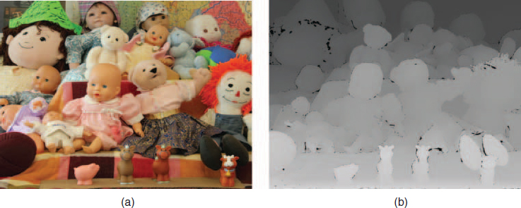
Figure 2.26 This demonstrates an example of image and depth maps of a real scene computed with [116].
2.4.2 Fundamental Concept Depth-Image-Based Representation
The main idea is to decouple the camera and the display geometry by deriving depth maps from capturing videos or images. This color and geometry decoupling strategy gives the high flexibility and adaptability at the receiver side. Fundamentally, the depth information can be estimated from a given stereo or multi-view video and will be shortly previewed in this section. More details will be discussed in Chapter 4. The color and depth information is delivered to the receiver and used to resynthesize a virtual stereo pair according to the viewer's condition and preference. This gives the perfect adaptability for display properties and related viewing conditions. Therefore, currently 3D content representations are usually based on the distribution of a single video plus the corresponding depth map for the central view to the receiver [118, 119]. The delivered content gives us the flexibility to compose stereoscopic images in real time at the receiver side. This concept also provides the backward compatibility to the original DVB system by encoding the monoscopic color video stream and the auxiliary depth information using the standard MPEG video coding tools [5, 120, 121] and the new MPEG H.264/AVC standard [5]. This allows 3DTV services to be built on the conventional 2D DVB system with a minor transmission overhead of about 10% for depth maps. It also means that the stereoscopic imagery is only generated during rendering at the receiver side and this allows for adapting the depth experience to different 3D displays and viewing conditions as well as to the user individual preferences [119]. An image can be generated by sampling the color for each pixel when looking through the pixel and intersecting the scene and then recording the image as shown in Figure 2.26. At the sampling points the color is gained according to the color appearance at that point and then all color information is recorded in a color map. The depth map is an extension to the color map. Additionally, the depth map is to record the depth information which is the value of the distance from the intersection point projected to the z-axis in the camera coordinate. Figure. 2.27 demonstrates the concept of synthesizing a new view at the receiver side for a virtual stereo setup used for view and display adaptation. As shown in Figure 2.27 the black dot is the real scene point in the original view, and the image in the new view can be synthesized by projecting the black dot into the new view.
According to the discussion in the previous paragraphs, disocclusion or exposure [122, 123] is an inherent drawback in the depth image-based representations. Disocclusion happens as shown in Fig 2.25 when the areas which are occluded in the original view become visible in the virtual views. Since the information about the originally hidden parts is missed from the transmitted monoscopic color videos and depth maps, the missing regions must be filled in with some smart mechanisms. These mechanisms include preprocessing (smoothing) the original depth data with a 2D Gaussian low-pass filter in order to avoid the appearance of holes, or interpolation from neighborhood pixels around the hole. For synthesized views with a relatively small amount of parallax [119], the filtering and interpolation methods can generate perceptually acceptable results. However, when depth effects are large or head-motion parallax (HMP) is involved, the image quality is generally not good enough. Thus, similar to multi-view coding (MVC), some systems proposed to use multiple depth image-based representations to overcome this limitation. In Chapter 5, we will discuss potential solutions to transmit this information efficiently.
2.4.2.1 Layer Depth Images
Depth-image-based representations can synthesize new views with high fidelity with a limited number of views transmitted through the network. However, color and depth information of all these views is transmitted at the same time, so the data rate will be huge. As a result, the concept of layered depth images (LDI) is proposed by Shade et al. [9] to solve this issue. Figure 2.28 shows a schematic example of different representations discussed previously in this section to compare the difference. A 3D scene (or object) in LDI is represented using a texture grid whose pixels contain a set of depth values from the main view and projected from the other view and the corresponding color information. The center of all views is generally chosen as the reference view and the depth plus image of the other views would be projected into this view. After projection, the depth of each projection point is compared against the reference depth value. If the depth value is larger than the reference, the projected point is behind the current reference point and LDI will record this extra projection point's depth and color information. In this way, LDI can record the difference between projection and the camera result as residual information. This residual information consists of disoccluded information, and is therefore mainly concentrated along depth discontinuities of foreground objects as well as image boundary data in both side views. When the compressed streams are received, the view synthesis consists of the following two fundamental steps:
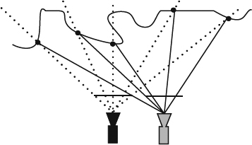
Figure 2.27 This illustrates the concept of the depth-image-based representation. The black camera represents the original view and black dots denote the scene position captured by the original camera. The gray camera represents the virtual view and all black dots are projected onto the image plane of the virtual camera.
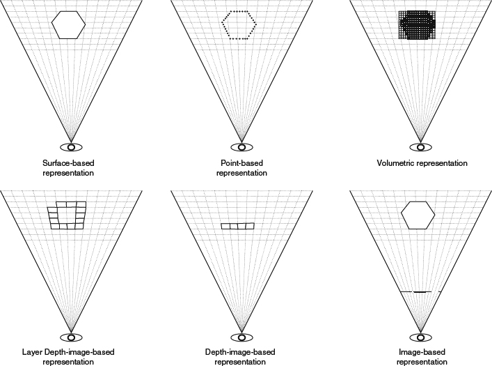
Figure 2.28 This uses a hexagon as an example to illustrate the concepts and data recorded for surface-based (discussed in Section 2.2.1), point-based (Section 2.2.2), volume-based (Section 2.2.6), layer-depth image-based (Section 2.4.2.1), depth-image-based (Section 2.4), and image-based (Section 2.3) representations. In the surface-based representation, six edges are represented as solid lines are used in the top-left. In the point-based representation, a set of points is represented as solid dots along the six edges in the top-middle. In the volume-based representation, a set of voxels is represented as solid-line squares inside the hexagon in the top-right. In the layer-depth representation, a set of intersections is represented as solid-line quadrilaterals along the intersection of view rays from the eye and all hexagon edges in the bottom-left. The intersections are recorded in the link list for each pixel with the values of color and depth. In the depth-image-based representation, a set of pixels is represented as solid-line quadrilaterals along the intersection of view rays and the front-face edges of the hexagon in the bottom-middle. The intersections are recorded at each pixel with the values of color and depth. In the image-based representation, a set of pixels is represented as a solid line on the image plane in the bottom-right.
- Layer projection: the central view is projected onto the intermediate view to synthesize the new view using DIBR.
- Intermediate view enhancement: fill the holes and cracks and filter the foreground objects to provide a natural appearance.
In this way, instead of sending all the images and depths, we only need to send one complete image and depth plus a residual depth and image information. This can reduce the amount of data transmitted [124]. The algorithms particularly take care of aspects of interoperability and multi-view adaptation for different baseline geometries used in multi-view capturing and rendering for 3DTV systems. There are more advanced solutions for creation of depth maps and depth image-based rendering related to multi-view adaptation needed in 3DTV system.
Similar to multiple-view depth-image-based methods, the number of original views and camera settings decides the navigation range and synthesized quality. Because LDI can save a large amount of storage space, layered depth video [114, 125, 126] is proposed to reduce the raw data rate for 3DTV drastically. On the other hand, since LDI is an extension to depth-image-based representations, reliable dense-depth extraction is still a problem in LDI. There is another serious boundary problem which often arises at depth discontinuities such as object boundaries or corners. Alpha-matting blends the depth values along the object boundary. When the discontinuity regions are identified, alpha-matting can be applied over those regions to significantly improve the output [127]. Therefore, to deploy a LDI-based representation, it is better to add an extra step, layer extraction, before the layer projection step. The layer extraction step uses edge detection to separate the image into reliable regions such as foreground, background, and boundary regions. The details are also discussed in Chapter 5.
2.4.3 Depth Construction
3D scanners mainly estimate the distance from the scanner to the point on the surface, and the distance can be directly transformed to the depth. The main research interests are in the reconstruction of depth using noncontact passive 3D scanners. Noncontact passive 3D scanners transform one or a set of 3D videos to 3D depth-image-based representations and thus the techniques are also called 2D to 3D conversion. Generally the algorithms can be categorized as:
- two or more images: two or more images are taken either by multiple cameras or by a single camera with the movement of the camera and objects. The depth cues are called multi-ocular depth cues.
- single image: the image is taken from a single camera by single shot. The depth cues are called monocular depth cues.
2.4.4 Depth-Image-Based Animation
Since the depth-image-based representations improve the image-based representation, they can give the reality of the world to the viewers by directly capturing the real world but they are also limited to generating the plausible and reasonable animation for changing viewpoints. This limitation does not affect their applications to current 3DTV systems. However, providing interactivity in depth-image-based representations is still a hot research topic. Because of the existence of depth maps, the interaction among captured content and adding virtual objects is easily defined and simulated and thus the augmented reality operations generally are designed to process in this representation. However, there is still a long way to go to achieve sufficient interactivity for interactive 3DTV systems.