
CHAPTER 14
OPERATING SYSTEMS FOR EMBEDDED SYSTEMS
This chapter discusses essential concepts of operating systems for embedded systems, such as tasks, scheduling schemes, coordination and communication between tasks, and operating system services. This chapter also introduces a lightweight, cooperative multitasking operating system for the Microchip PIC24 μC family. Several example applications are provided.
Learning Objectives
After reading this chapter, you will be able to:
![]() Describe the difference between cooperative multitasking, preemptive multitasking, and programming.
Describe the difference between cooperative multitasking, preemptive multitasking, and programming.
![]() Write pseudo-code to outline an application with concurrently executing tasks using cooperative and preemptive multitasking approaches.
Write pseudo-code to outline an application with concurrently executing tasks using cooperative and preemptive multitasking approaches.
![]() Create example situations where semaphores or messaging can solve problems with synchronization and coordination.
Create example situations where semaphores or messaging can solve problems with synchronization and coordination.
![]() Use the Embedded Systems Operating Systems (ESOS) on the PIC24 μC to write multitasking applications.
Use the Embedded Systems Operating Systems (ESOS) on the PIC24 μC to write multitasking applications.
![]() Use the services provided by ESOS to generate software timers, respond to hardware interrupts, and communicate serially via synchronous and asynchronous protocols.
Use the services provided by ESOS to generate software timers, respond to hardware interrupts, and communicate serially via synchronous and asynchronous protocols.
![]() Develop additional services for ESOS.
Develop additional services for ESOS.
The applications developed thus far in this book have been based on a pattern of hardware initialization followed by an infinite loop written in a way that is specific to the application at hand. This program structure is very straightforward and used in many embedded system applications that operate flawlessly every day. While efficient, this approach can be difficult if the application specification were to grow or if the application changes. Furthermore, much developer time is spent creating software infrastructure that will likely be needed again in future applications. The hardware support library used in the previous chapters is an attempt to create software resources that will speed development and lead to higher quality software designs. The operating system extends the concept of creating a more generic software framework. Operating systems provide basic services and perform common software housekeeping tasks that advanced embedded system applications can use. This chapter looks at some basic principles of operating systems and introduces an operating system suitable for the PIC24 μC that can be used in advanced or complex embedded system projects.
Operating System Concepts
You are no doubt familiar with operating systems (OSes) for general-purpose desktop and laptop computers. Examples of popular desktop and laptop OSes are Microsoft Windows, Apple’s Mac OS X, and Linux. Often, people forget that the pretty graphical interface that represents the “computer desktop” they see is not the operating system, but merely the windowing system application running atop the OS. In actuality, the OS is the system software underneath that is responsible for coordinating the use of the hardware for applications that run on the computer. These applications include the window manager, word processors, web browsers, email clients, and games.
OSes are not limited to desktop and laptop general-purpose computers. OSes can be found in most every computer system that has a reasonably complicated function to perform. OSes are literally everywhere—in your smart phone, your Internet router, and several OSes power different controllers in your automobile. There is probably an OS controlling the microwave to pop your popcorn. In fact, the most widely used OS on earth is probably an OS for embedded systems: TRON, and its derivatives, grew out of a project at the University of Tokyo in the 1980s [76]. TRON is really a software specification that has been implemented by a huge number of embedded device manufacturers of consumer devices, ovens, refrigerators, digital cameras, CD players, mobile phones, industrial controllers, and cash registers. Since TRON is a specification, as opposed to source code, the exact number of TRON systems in use is pure speculation. Estimates are in the hundreds of millions, if not billions, of copies.
OSes can vary from hugely complex pieces of software (Microsoft Windows, Apple Mac OS X, and Linux) to very simple constructs that simply coordinate several tasks on a small microprocessor like the PIC24 μC.
Although these OSes differ in size and style, most OSes offer fundamentally the same services to their hosted applications:
![]() Control program/task execution
Control program/task execution
![]() Provide a scheduler, which determines the sequence in which programs/tasks execute
Provide a scheduler, which determines the sequence in which programs/tasks execute
![]() Provide a consistent system in which the system can provide program execution to unexpected requests generated by hardware interrupts
Provide a consistent system in which the system can provide program execution to unexpected requests generated by hardware interrupts
![]() Provide high-level functions or services to access and control hardware, including timers, peripherals/devices, and memory
Provide high-level functions or services to access and control hardware, including timers, peripherals/devices, and memory
From the preceding features list, you can see that OSes can provide the embedded systems designer fundamental operations required to keep the software application running. Furthermore, these operations are needed by almost every software application and are not specific to any particular functionality. Instead of burdening the application developer with creating the code to provide these features, the OS contains them, leaving the developer free to concentrate on application-specific code.
The OS controls program or task execution by creating a context in which a program can run, and then initiates code execution. This program or task context may be a dedicated processor in a multiprocessor computer, a protected memory space, or simply a stack frame, depending on the OS and its hosting hardware. The OS scheduler is responsible for determining which program or task executes next. The scheduler may use a complex algorithm based in queuing theory or operations research to select the next task to run, or the scheduler may simply run each process in a “round-robin” manner. The OS should also provide a system by which hardware peripherals can interrupt normal program flow. Interrupts are intimately related to the ISRs that service them. Since an OS is ultimately responsible for program execution, the OS must be apprised of and manage the software that responds to interrupts. The usual approach is that an OS provides its own methods for enabling and disabling interrupts, setting interrupt priorities, and selecting software routines to respond to interrupts. Finally, OSes typically provide methods by which the user’s application code can access and control hardware. Most often, OSes provide methods for timer resources. Many OSes supply methods for accessing other peripherals such as memory, file systems, and communications. Many, but not all, OSes provide additional services depending on the OS’s goals and the capabilities of the underlying hardware. These additional services can include but are not limited to:
![]() Multitasking
Multitasking
![]() Protected execution modes
Protected execution modes
![]() Memory management
Memory management
![]() Services for communications between application tasks and between computers (networking)
Services for communications between application tasks and between computers (networking)
![]() Task execution within fixed timing deadlines
Task execution within fixed timing deadlines
Multiprocessing is the use of multiple processors to perform several differing computing activities simultaneously. Multitasking is a method by which multiple computing processes share the same processor, and resources appear to be running simultaneously. The discussion in this chapter deals almost exclusively with a single processor, multitasking system. Consider an MP3 music player as an example of a multitasking embedded computing system. Your MP3 music player likely has only one central processor, which is used to control the music decoding and audio playback. This same central processor is also responsible for drawing the display screen updates and graphics and for sensing the state of the human-machine interface such as buttons and scroll wheels. Use cases for the MP3 music player demand that the screen updates and the buttons respond during audio playback. The MP3 music player’s OS provides multitasking so that the music playback, screen updates, and button sensing appears to occur at the same time. Similarly, the OS on your desktop or laptop computer provides multitasking so that you can download email while playing a computer game and messaging with your friends. The specific functions of the MP3 music player and the desktop/laptop computer are quite different, but both need multitasking, which is provided by the OS. Methods by which multitasking are performed vary but the illusion of concurrent execution is the same.
Some OSes support protected execution modes where programs/tasks are limited in the machine instructions and resources that they are allowed to use. In this way, the OS can more easily manage and protect the limited computing resources under its control. Since it is difficult for OS software to control the machine instructions used by the programs it runs, protected execution modes are available only when the underlying hardware provides this capability.
Some OSes provide memory management services. Memory management is the action of an OS to efficiently manage and utilize its available memory. Memory management by an OS is largely a software solution, so memory management is potentially available in any OS.
An OS can provide additional memory management functions like memory protection. Memory protection is a scheme by which a program’s or task’s memory is protected from unauthorized access by other programs and tasks. Like protected execution modes, memory protection usually requires hardware support to detect and limit the addressing activities of programs. Without sufficient hardware support, OSes often cannot provide memory protection.
Since computers are so often connected to other devices and computers, many modern OSes provide communications services. The TCP/IP stack on Ethernet is an example from the desktop/laptop computers that immediately comes to mind. Modern desktop/laptop computers also communicate with other devices via the Universal Serial Bus (USB) and IEEE 1394 (also known as “FireWire”) protocols. Embedded computers also communicate with other computers, and often do so with a much wider variety of communication protocols, such as CAN, SPI, I2C, and other serial channels such as RS232, RS422, and RS485. OSes for embedded systems may provide methods for communications on one or more of these protocols, which hide the details of the protocol from the application developer.
Many embedded systems are reactive systems, that is, systems that react to and maintain ongoing interactions with their environment. These systems generate responses rather than a final result or value. Many control systems, like an airplane’s avionics or the controller for an industrial plant, are reactive systems. Reactive systems often must respond within a very tightly specified time period for proper operation. These types of reactive systems are often called real-time systems. A special OS called a real-time operating system (RTOS) exists that performs many or all of the OS functions listed earlier, but does so with a guarantee of response time. Furthermore, RTOSes can also guarantee their tasks will run a certain number of times with a maximum interval between executions. In this way, designers can count on their code having a very specific temporal behavior, which is critical for many of these control-oriented embedded system applications.
A detailed discussion of these OS topics can easily fill several volumes. You can delve into OS details in [71]–[73]. This section briefly introduces the concepts of OSes needed for this specific discussion and application of an OS for embedded systems.
Tasks
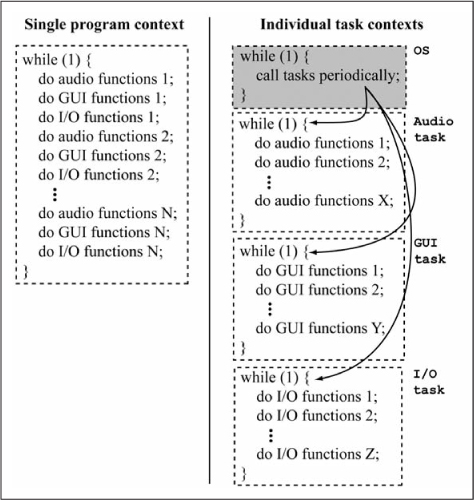
Computer applications can usually be described as a collection of tasks, where a task is defined as a sequence of computer instructions within a context. All of the software applications in this text fit into this description if you assume a single context: the entirety of your sequentially executing application code. The single application context becomes troublesome as the application grows in complexity. Typically, an application has several functions to perform and these functions are not necessarily dependent upon the others. An application is more maintainable if functionality can be coded such that unrelated activities are not interspersed. Figure 14.1 shows pseudo-code for an MP3 music player. The MP3 player must continuously play music, update its graphical user interface (GUI), and monitor its input/output (I/O) system for user requests. Furthermore, the MP3 music player must appear to perform all three functions simultaneously. If the MP3 player has a single microprocessor, it must interleave the functions for the three subsystems—audio, GUI, and I/O—to give the appearance of multitasking. In case of a single programming context, the functions of the three subsystems must be interleaved in a single while (1) loop by the programmer. In order for each of the three subsystems to run while giving the appearance of simultaneous execution, Figure 14.1 shows each subsystem divided into N subroutines, each with the same execution time. Code readability, reuse, and maintainability are difficult in the program form in the left side of Figure 14.1.
If the MP3 music player uses an OS that supports task switching, the code for the three independent subsystem tasks can be kept separate. The right side of Figure 14.1 shows the form of task-oriented software. In this implementation, each of the three subsystems is written in its own while (1) loop, as if it existed alone. However, the OS has the ability to suspend a task’s execution and give control over to another task. The methods by which this can be done will be introduced shortly. Clearly, the individual task contexts allow independent tasks to be written without mixing in code from unrelated operations. Since each subsystem exists independently of the other tasks, each task can be broken down into as many or as few steps as required. This approach with independent tasks written without concern for other application functionality is logically more consistent with the user’s perspective, is simpler for the designer, and is not as error-prone as the code form shown in the left side of Figure 14.1.
Figure 14.1
Three tasks of an MP3 music player
Multitasking and Schedulers
As defined earlier, multitasking is the ability to seemingly execute more than one task at a time with only one processor. The OS gives the appearance of simultaneous execution by allowing each program or task to execute for a short period of time before switching to another program or task. The switch from one program to another is so rapid and often that the user perceives all of the programs running at the same time. This form of multitasking is called time-sharing execution.
There are two basic types of time-sharing multitasking: preemptive and cooperative. In preemptive multitasking, the OS maintains a tally of how much CPU time each program task has used since the last task change. After a suitable period has elapsed, the OS suspends the task at its current operating point and activates/reactivates the next task to execute. Preemptive multitasking gives the OS complete authority in determining which tasks run, when they run, and how long they run. In cooperative multitasking, each task can execute in the CPU for as long as it needs to. If a task does not need the CPU, the task should voluntarily allow other programs or tasks to use the CPU. In cooperative multitasking, the sharing of the single CPU and its resources is reliant on each task cooperating with the sharing scheme. If a task decides to be selfish, it can monopolize the system and starve the other tasks of CPU time. The OS has no real power to stop this kind of bad task behavior, and the simultaneous execution illusion is destroyed.
To place multitasking methods into context, let’s examine some historical operating systems for desktop and laptop PCs. The Disk Operating System (DOS) of the 1980s did not support multitasking. DOS programs had sole control of the computer and its resources. Microsoft Windows 3.x and the MultiFinder-based Apple Macintosh OSes (versions of Mac OS up through Mac OS 9) use cooperative multitasking. All programs written for these OSes must voluntarily cooperate for multitasking to occur. Obviously, programmers of these applications intended to cooperate. However, application code defects or hardware errors sometimes caused a program to fail to yield the CPU. The appearance to the user was that a program either monopolized the processor or the system would hang completely. The Amiga OS released in 1985, IBM’s OS/2 released in 1987, Microsoft OSes Windows 95 and later, Mac OSX released in 1999, all UNIX OSes since the first 1971 release, and Linux OSes use preemptive multitasking. Since these OSes are in complete control of task execution, a defective program or a hardware-induced hang usually can be stopped by the OS.
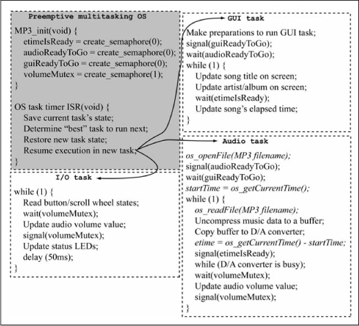
The change from one task to another is called a context switch. In preemptive multitasking, the OS must determine when to execute a context switch. In its attempt to be fair to all running tasks, preemptive multitasking OSes must determine how much CPU time each task has used. OSes tally either the physical time period that a task has held the CPU since the last context switch, or the number of CPU instructions executed by the process since the last context switch. The latter approach is aided by special instruction count registers present in many of the large, modern processors. The former approach is readily accomplished with timer hardware and its associated interrupt. Because context switches in preemptive multitasking systems are determined completely by the OS, application code does not explicitly contain any code for context switches. Figure 14.2 shows the pseudocode for the example MP3 player under a preemptive multitasking OS. Each task runs as if in isolation from the other tasks and is completely unaware of when context switches occur. When the OS determines the time is appropriate for a context switch, the OS interrupts the current task, saves the current task’s state, recreates the saved state of another task, and resumes execution of this restored task at the point where it was last interrupted. It is the OS’s sole responsibility to save and restore the CPU registers, memory contexts such as stack frames, and program counters appropriately.
Figure 14.2
Pseudo-code for an MP3 music player written with a preemptive multitasking OS
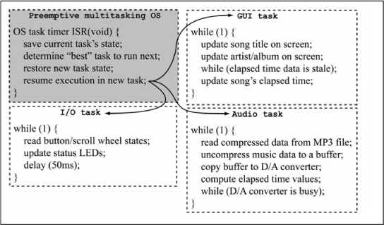
In a preemptive multitasking OS, the OS determines when the context switch should occur. While this can provide protection against an errant task monopolizing the CPU, it also has the potential to be inefficient. Consider the 50 ms delay in the I/O task in Figure 14.2 running in an OS that provides its tasks with access to a variable that represents a 1 ms counter via a call to os_getCurrentTickValue(). The 50 ms delay in Figure 14.2 can be implemented by waiting for 50 ticks of the OS timer to elapse. Listing 14.1 gives possible pseudo-code for a suitable delay subroutine in the multitasking OS.
Listing 14.1: Simple Delay Routine for Multitasking OS
void delay(u16_delay) {
  uint16_t u16_initTickVal;

  // record OS tick count when delay routine is first called
  u16_initTickVal = os_getCurrentTickValue();
  // wait until u16_delay milliseconds have elapsed since first call
  while (os_getCurrentTickValue() - u16_initTickVal <= u16_delay);
}
Assume that the OS running the code in Listing 14.1 and Figure 14.2 gives each task 10 ms slices of CPU time before switching to another task. Depending on the number of tasks running, it is possible that the 50 ms delay in Listing 14.1 will use each of its 10 ms execution periods just wasting CPU cycles. Other tasks are denied CPU time while the I/O task waits for time to elapse. The CPU can be better utilized if the OS were somehow informed of the I/O task’s intentions to wait for 50 ms and not require CPU time.
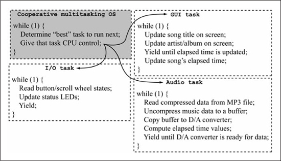
In cooperative multitasking, the tasks determine the appropriate time for a context switch to another task. Typically, cooperative multitasking tasks hold the CPU focus until they cannot continue further without additional information or input. For example, consider the MP3 player application coded with a cooperative multitasking OS. The GUI screen update task uses the CPU to update the screen with the song title, album title, and artist name. However, the GUI task cannot correctly update the screen with the song’s elapsed playing time until the audio playback task provides this information. Since the GUI task does not have the correct elapsed playing time information, the GUI task signals the OS that a context switch should occur. In fact, the GUI task should somehow let the OS know that the CPU should focus on other tasks until the elapsed playing time is provided. Figure 14.3 shows the MP3 player application written in pseudo-code for a cooperative multitasking OS. In cooperative multitasking OSes, the OS must provide a rich enough set of functions for tasks to communicate their needs and intent to the OS and other tasks. When a task requests a context switch, the OS should examine the tasks’ desires and states, and switch to the task that is willing and able to execute. Since tasks determine the exact times at which a time context switch can occur, the tasks themselves can be expected to have more responsibility and efficiency in preserving their state across these context switches. Because of the cooperation between tasks and the OS, cooperative multitasking OSes can be substantially simpler software at the expense of more complicated task code. The cooperative multitasking OS is conceptually very efficient in terms of CPU time if programmed properly. The task with CPU control maintains control until it can no longer fully utilize the CPU. When the task is not fully consuming CPU resources, it should relinquish CPU control to a task that can fully utilize the CPU. Cooperative multitasking programs do not get processor time at uniform intervals or for uniform periods of time, but they are not given a CPU time-slice when they don’t need it either.
Figure 14.3
Pseudo-code for an MP3 music player written with a cooperative multitasking OS
Inter-Task Coordination: Semaphores
Multitasking environments are likely to have multiple tasks competing for a finite resource. Since tasks are coded in a way that they appear to be running in isolation, the finite resource problem requires that tasks have a method by which they can coordinate their execution and meter use of the finite resource. For example, two independent tasks may need to write the same global variable. The write operations must be synchronized so that the two writes do not disturb each other. Another common issue with multitasking OSes is that two or more executing tasks will likely need to be synchronized in their execution. In other words, a task must be sure that one or more other tasks have progressed to a particular point before the first task can continue execution. Two popular methods by which tasks coordinate and communicate are semaphores and messaging.
The famous computer scientist Edsger Dijkstra developed the concept of semaphores to solve these problems. Semaphores are a protected variable used to synchronize execution. The problem of finite resource use can also be solved through semaphores. Semaphores are defined in a more formal context in this chapter than the global variables used in previous chapters for synchronizing interrupt code actions with main() code.
Modern multitasking OSes all provide some form of semaphore to their applications. Semaphores are a powerful technique that can solve a great deal of problems in concurrently executing systems such as multitasking OSes. You’re encouraged to delve into the free online book [74] for a deeper discussion of semaphores.
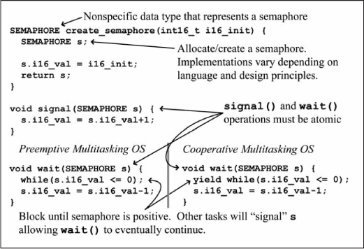
Semaphores in computing are named after their physical counterparts, where a semaphore is a visual signaling system usually implemented with flags, lights, or other mechanical means. Military and marine endeavors used semaphores extensively for centuries before the advent of radio communications. Even today, semaphores are used by ships within close proximity when radio communications are not possible. Computing semaphores also implement a signaling system. Figure 14.4 shows the three simple functions allowed by the computing semaphores: create_semaphore(), signal(), and wait(). Semaphores must be created: the C language pseudo-code for create_semaphore() allocates storage for the semaphore and initializes its value to a number provided by the caller. The allocation method of the actual semaphore storage in Figure 14.4 is left ambiguous as the exact means can vary depending on the OS, memory management, and language in use. The semaphore function signal() atomically increments the semaphore value; that is, the signal() function cannot be interrupted while it increments the semaphore value. Finally, the semaphore function wait() blocks the current task until the semaphore value is positive, then decrements the semaphore value. A positive semaphore value authorizes tasks waiting on that semaphore to proceed. Decrementing the semaphore value indicates to other tasks that a task has signaled the semaphore. That is, the task has seized the finite resource and will increment the semaphore once it is finished with the resource.
Remember that you are working in a multitasking system. A task may be blocked waiting on the semaphore while other tasks will continue to execute and potentially signal, or increment, the semaphore.
Notice that apart from the creation of the semaphore, the semaphore functions cannot provide the exact value of the semaphore to the caller. In practice, the caller has no need for the actual semaphore value. With these three simple semaphore functions, you can solve a variety of computing coordination problems. Later in this chapter, you will see semaphores in action.
Figure 14.4
Pseudo-code for basic semaphore operation in a multitasking OS
Inter-Task Coordination and Communication: Messaging
As you saw in the previous section on semaphores, multitasking environments have tasks that need to be coordinated or synchronized. Often tasks in a multitasking application that are related enough to require coordination also share data with each other. Sometimes, the system designer uses semaphores for coordination and some other mechanism like global variables or memory to share data. Another approach used to coordinate tasks and communicate data between tasks is based on a system that dates back to the creation of written language thousands of years ago: the postal system. While the motivation for messaging systems in computers could come from the practice of electronic mail, we will use the typically government-sponsored postal or mail system that delivers physical envelopes and paper to your home as the motivator for this discussion.
First of all, the postal system is designed to be easily used. The mailbox at your residence is likely very prominently located to make the postal delivery easy. The mailbox prominence and its design also make it very easy for you to check for the presence and recovery of your incoming mail. It should be easy to see that the mail system provides task coordination. The actions of millions of people are coordinated every year in filling out forms for data collection or tax collection based on the reception of an envelope or a postcard in their physical mailbox. Likewise, a notice from some creditor demanding payment usually prompts an action. In other situations, some party desires to initiate an action based on the information that you received their notice and should be undertaking some action yourself. For example, governments typically send summons to perform jury duty via certified letter. Upon receiving a notice for jury duty, the recipient is expected to contact the court or simply show up at the appointed date and time. Your receipt of the jury duty notice is recorded by the postal system. If you fail to act as prescribed in the jury duty notice, the court will take some action (issue a warrant for your arrest) based on their knowledge that you did, indeed, receive the notice.
There are other bits of information common in postal systems that are useful, if not absolutely essential. It is doubtful that many people when receiving an unusual looking envelope or package in their mailbox open it without first looking at the return address to see who sent the parcel. Another useful feature of modern postal systems is the postmark. The postmark on an envelope or package denotes when the parcel was sent. Postmarks are often used to determine whether the mailer/sender met some deadline. Postmarks are used by the curious to calculate the period of time required to receive a postcard mailed by a friend vacationing in some faraway land.
Using the postal system as an example, you can see that program tasks could benefit from a similar system to provide coordination and data delivery. The computer messaging system created for these tasks should have the following capabilities:
![]() Tasks can send messages containing a wide variety of data.
Tasks can send messages containing a wide variety of data.
![]() Messages can be sent to arbitrary task.
Messages can be sent to arbitrary task.
![]() Messages contain information about who sent the message.
Messages contain information about who sent the message.
![]() Messages contain time information about when message was sent.
Messages contain time information about when message was sent.
![]() Tasks have the ability to determine when their sent messages are received by their recipients.
Tasks have the ability to determine when their sent messages are received by their recipients.
![]() It should be relatively easy for tasks to send messages, check for incoming messages, and read any incoming messages.
It should be relatively easy for tasks to send messages, check for incoming messages, and read any incoming messages.
Many modern OS systems provide messaging services. Most provide the capabilities just listed and much more. The exact method by which the messaging service is implemented and the associated application programming interface depends on the application, the hardware, and the needs of the users.
OS Services
Operating systems often provide a variety of services for their applications. The number and types of services provided by OSes vary widely. Simple OSes for resource-constrained embedded systems may provide only the most basic services of system time-keeping and task management, while OSes for desktop computers provide services for memory management, networking, multimedia, graphical windows systems, computer security, remote access, installable file systems, and many more. OS services are specific to the underlying OS; therefore, this section provides a couple of simple OS services examples that may be used in the MP3 player example.
One of the most common services provided by OSes is a time service. All microprocessors have some kind of hardware timer. Also, the hardware timers in microprocessors vary widely in setup, capabilities, and use. Therefore, OSes often provide hardware-independent means of obtaining timing information through their time service.
Nearly all embedded systems manipulate data. An OS file service provides basic file manipulations like opening, closing, creating, and deleting files. Services for dealing with data within files may include reading, writing, and searching, and random-access seeks. In a multitasking OS, file services for file locking, ownership, and access permissions are common. OSes with large capacity files systems may provide services for directory management and fragmented file storage.
The number and types of services in an OS can vary widely. The selection of services often plays a big part in the justification to use one OS over another. The details of the services provided are specific to a particular OS. Since the MP3 example has not specified a particular OS, we leave the details on the OS services as somewhat vague. However, we assume that the OS for the MP3 example provides services for file management, semaphores, and timekeeping. Figure 14.5 shows the pseudo-code for the MP3 example using an OS with file and time services. Of course, your chosen OS may provide additional services over those used in Figure 14.5. The next section introduces a simple OS that can run on members of the PIC24 μC family.
Figure 14.5
OS services in an MP3 player
Embedded Systems Operating System for the Microchip PIC24 μC
The code examples in the previous chapters had simple program organization where the hardware peripherals and software structures are initialized, then timers and interrupts are enabled, and, finally, the software enters an infinite loop to handle requests and dispatch commands. In this structure, the while (1) infinite loop in the main() routine handles tasks that do not require rapid response or have strict deadlines. Interrupts and hardware peripherals run as required for tasks that do require quick action or occur too fast for sequentially executed code to perform. To this point, this way of organizing programs has served you well. However, as your embedded system designs grow in complexity, this method of organizing embedded systems code can become difficult to maintain. Code for dealing with a particular function gets distributed in the main() routine and various ISRs along with the code for several other functions. Program flow control is poorly documented and is usually determined only by careful and detailed study of the firmware source. As the number of ISRs increase, determination of stable program execution flow becomes impossible. There are too many possible combinations of pending interrupts. What a complex embedded systems design needs is a multitasking OS. Since the PIC24 μC has relatively limited resources such as instruction throughput and memory, you need the multitasking OS to be very efficient in its resource requirements.
This section describes the structure and operation of the embedded systems operating system (ESOS). ESOS is a cooperative, multitasking embedded systems framework based on the protothreads concept by Swedish computer scientist Adam Dunkels [75]. Protothreads are extremely lightweight threads of program execution. Protothreads differ from normal threads in that they are not preempted and are stackless. However, Dunkel’s protothreads allow ESOS to provide event-driven flow control in a very readable fashion and allow for blocked program tasks to give up processor focus so other tasks can run. Finally, protothreads require only a few bytes of memory of overhead to maintain their state.
The protothread library is written in ANSI-compliant C code, so protothreads are available in nearly every high-quality C compiler. Protothreads are created by an interesting C language specification that allows switch() statements to generate local continuations, a representation of the current state of execution at a particular place in the program. This interesting behavior of the C language was first discovered in 1983 by Lucasfilm computer scientist Tom Duff and has been named “Duff’s Device.” A study of Duff’s Device and the details of how local continuations are implemented in ESOS is beyond the scope of this book. You’re encouraged to dig deeper by looking at the ESOS source code esos_task.h.
While understanding local continuations, Duff’s Device, and protothreads will help you to understand better ESOS and its architecture, this knowledge is not required. What you must know is that ESOS uses these concepts to create a cooperative multitasking OS in which you can write your applications. In addition to providing you with cooperative multitasking execution, ESOS also provides several very useful services such as semaphores, messaging, interrupts, software timers, and serial communications. The remainder of this chapter is devoted to explaining the basic structure of ESOS and the organization of user programs written under ESOS. This chapter concludes with several example applications written with ESOS.
ESOS Overview
ESOS provides a cooperative multitasking environment for ESOS tasks, ESOS services, and user tasks to execute. ESOS is responsible for managing computing resources for its tasks, services, and user tasks. To perform this function, the ESOS system code needs priority over all user tasks. ESOS initializes and controls the PIC24 μC execution, interrupts, and peripherals. Figure 14.6 shows a block diagram of the execution of a typical user application written with ESOS.
Figure 14.6
Basic execution flow of an application written with ESOS
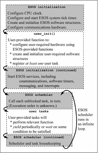
ESOS is responsible for the clock initialization, the timer used by ESOS to generate a reliable system tick, the UART used by ESOS to provide a serial communications service, and the interrupts used by ESOS internally. After ESOS has performed most of the hardware configuration, ESOS calls a subroutine user_init() provided by the user. In user_init(), the user initializes the hardware peripherals and software structures required for the user’s application. User configuration of interrupts done in user_init() is done by calling functions provided by ESOS to manipulate interrupt settings. ESOS must be kept aware of the state of interrupts so that ESOS can manage the interrupt system as a whole. The routine user_init() is fundamentally equivalent to the initialization code you execute before the while (1) infinite loop in the code written in the earlier chapters. Before user_init() returns, it must register at least one user task with ESOS. As you can see in Figure 14.6, the ESOS scheduler is started soon after the user_init() concludes. If no user tasks are registered with ESOS when the scheduler starts, then the scheduler has nothing to execute. The scheduler will simply run its infinite loop looking for unblocked tasks that do not exist.
After user_init() returns, ESOS completes its initialization and starts the ESOS task scheduler. The ESOS scheduler is equivalent to the familiar while (1) infinite loop in the previous chapters. Repeatedly, ESOS gives CPU control to each unblocked task. Each task executes its code until it decides to yield control back to the ESOS scheduler. Tasks signal their willingness to yield control through several function calls provided by ESOS. These functions allow the task to inform ESOS upon what condition the task is waiting. Thus, ESOS can give focus back to the task when the condition is satisfied.
User Tasks
The user-written task functions called by the ESOS scheduler implement the desired functionality in ESOS-based applications. These tasks cooperate with the ESOS scheduler by yielding control when they need additional data or they need another task to execute to a particular point. ESOS provides a rich programming interface for user tasks to manage task states and communication between tasks. This section provides a reference of ESOS functions to create tasks, manage tasks, communicate with other tasks and ESOS, and remove tasks with nothing left to do. Figure 14.7 shows the user task structure. The user task in Figure 14.7 uses nearly all of the task-management function provided by ESOS. The user tasks you write will likely not have as many different task “waits.”
Each user task must begin with a declaration to the compiler that the code that follows is an ESOS task, not a normal C language function. Each user task begins with the statement ESOS_USER_TASK(taskname) followed by a code block, where taskname is a unique name by which the task is known. In practice, a user task is actually a C language function, so the name you choose for your task must adhere to requirements of the C language for function names.
User tasks are actually C language functions. Therefore, your user task can declare local variables that have scope only within the context of that user task. However, the automatic variables (i.e., variables that are not qualified static) have scope restricted to the code portion where they are assigned a value until the next ESOS function to wait or yield. The implementation of user tasks in ESOS is based on repeated C language calls to a function. Each time a context switch goes to a user task, the ESOS scheduler is actually making a call to the function that implements the user task. When a context switch occurs away from the user task, the implementation is actually performing a C language return back to the ESOS scheduler. When a C language function returns, all automatic variables are lost because the stack frame resets to that of the calling function. Of course, you know when a context switch potentially will occur in your cooperative multitasking OS: whenever the user task makes a call to an ESOS function to wait or yield. If you need the user task to remember the variable value across waits and yields, you must declare these variables as static. Resist the urge to qualify all user task variables as static because this consumes valuable memory resources.
Figure 14.7
Representative user task code using many ESOS task-management functions

Since user tasks in ESOS are really just C language functions, a context switch to a new ESOS task is, in reality, simply the ESOS scheduler calling the function that implements the user task. In fact, the ESOS scheduler calls your task function repeatedly to determine if any blocking conditions have expired. The statement ESOS_TASK_BEGIN() in Figure 14.7 is the code that performs the actual restoration of your task state when the context switches back to your task. Therefore, any code statements that are in your user task before the statement ESOS_TASK_BEGIN() are executed every time the ESOS scheduler calls the task. The statement ESOS_TASK_END() tells the C language compiler that the user task has been completely defined and completes the coding structures created by ESOS_TASK_BEGIN(). At run-time, the statement ESOS_TASK_END() notifies the ESOS scheduler that your task is complete. The statement ESOS_TASK_END() should be the last line of code in every one of your user tasks. Any code after ESOS_TASK_END() is never executed. Any user tasks called taskname defined with the declaration ESOS_USER_TASK(taskname) must have both a call to ESOS_TASK_BEGIN() and ESOS_TASK_END(). If not, a compiler syntax error is generated.
Cooperative multitasking OSes such as ESOS work only when their application’s tasks voluntarily give up the processor for other tasks to run. Cooperative multitasking OSes encourage good citizenship in their tasks by providing a rich selection of functions to allow tasks to give up focus but only for very specific conditions. Thus, the task is assured of getting the processor focus again exactly when it is first able to utilize the processor. The ESOS system provides several function calls to allow its tasks to very specifically give up focus. Figure 14.8 shows a summary of the major ESOS calls that can potentially cause a task to lose focus. As you will soon see, ESOS services extend this concept by providing service-specific functions that tasks can call to give up focus while they wait for the service to perform its function.
Figure 14.8
ESOS calls that can cause the current task to wait or yield
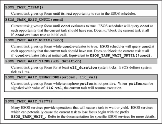
The statement ESOS_TASK_YIELD() is the simplest of the task blocking statements in ESOS. This statement gives up control of the processor unconditionally but temporarily. The statement ESOS_TASK_YIELD() allows other tasks to execute one time before resuming. The task that calls ESOS_TASK_YIELD() resumes execution at the next time that the ESOS scheduler gets around to my_user_task in the task rotation. If all other tasks in the application are cooperating properly, a call to ESOS_TASK_YIELD() will results in a very short loss of CPU focus. A well-behaved cooperative multitasking task should, at the very least, break long computations into smaller chunks with ESOS_TASK_YIELD() statements between chunks, and the programmer must make sure that only static variables are being computed. This gives other tasks the opportunity to execute.
The statements ESOS_TASK_WAIT_UNTIL(cond) and ESOS_TASK_WAIT_WHILE(cond) give up processor focus based on a condition cond. The statement ESOS_TASK_WAIT_UNTIL(cond) gives up focus until the condition cond is true, while ESOS_TASK_WAIT_WHILE(cond) gives up focus until the condition cond is false. For example, if cond is true when the task calls ESOS_TASK_WAIT_UNTIL(cond), the task does not yield and continues executing. In theory, tasks that contain only ESOS_TASK_WAIT_UNTIL(cond) and ESOS_TASK_WAIT_UNTIL(cond) statements could monopolize the processor. In practice, this is unlikely to happen.
Where ESOS_TASK_YIELD() yields processor control unconditionally but temporarily, the statement ESOS_TASK_SLEEP() yields control unconditionally and indefinitely. The task that calls ESOS_TASK_SLEEP() is put to sleep. The sleeping task does not execute again until some other task calls an ESOS function that wakes the sleeping task. At that point, the sleeping task resumes execution at the statement following ESOS_TASK_SLEEP(). Note that a sleeping ESOS task is simply suspended from executing by the ESOS scheduler and is unrelated to putting the processor to sleep to conserve power.
ESOS maintains an internal system clock, which you will see shortly when you read about ESOS timer services. Since ESOS is keeping track of time periods, your task can yield processor focus for a specific period of time. When my_user_task calls ESOS_TASK_WAIT_TICKS(n), the task my_user_task resumes execution at its first possible opportunity after n system ticks have elapsed. The current implementation of ESOS defines a system tick as 1 ms. The call to ESOS_TASK_WAIT_TICKS(1000) in Figure 14.7 causes my_user_task to give control to other tasks for at least 1.0 seconds.
Now that you know how to instruct a task to yield its control of the processor, you must learn exactly how the task gets placed into the task rotation by the ESOS scheduler. Recall from Figure 14.6 that you must register at least one task with ESOS during user_init(). If user_init() registers one task, it will run when the scheduler starts. That task is free to register other tasks with ESOS at any time and these new tasks will enter the round-robin task rotation. The ESOS function to register a user task is called esos_RegisterTask(taskname). For the example in Figure 14.7, the correct call is esos_RegisterTask(my_user_task). The function esos_RegisterTask(taskname) returns a variable of the type ESOS_TASK_HANDLE. Your application may want to save the returned ESOS_TASK_HANDLEs if you plan on having tasks control other tasks or coordinate with other tasks. If your tasks simply run through their life cycles in relative isolation, there is no need to save the returned task handles.
ESOS also provides an esos_UnregisterTask(taskname) function. In practice, your applications will rarely call this routine. Let’s look at end-of-life for the task in Figure 14.7. When your my_user_task concludes (i.e., executes ESOS_TASK_END()), the ESOS scheduler removes my_user_task from the task rotation list. At this point, some other running task could call esos_UnregisterTask(my_user_task), which would completely free up all the memory ESOS allocated to manage my_user_task. While polite, this action is unnecessary as ESOS knows that my_user_task has ended and will automatically free this memory when the time comes that ESOS truly needs it. A task could call esos_UnregisterTask(my_user_task) while my_user_task is still actively running. This would result in my_user_task being removed from the task rotation and its memory freed. As you will see shortly, ESOS provides less strong-armed tactics for control of other tasks than just ripping them out of the scheduler and memory with esos_UnregisterTask.
Your First ESOS Program
Users must provide at least two program items in order for ESOS to generate a usable application. First, the user must provide a user_init() function. Secondly, the user must provide at least one user task that is registered in user_init(). Armed with these rules and the ESOS task-management functions in the previous section, you are ready to create your first ESOS program. Figure 14.9 shows the code for an ESOS program to flash an LED connected to RB15. This code runs on a dsPIC33EP128GP502 setup similar to the reference system of Chapter 8. The code in Figure 14.9 implements the same basic functionality as the code in Figures 8.4 and 8.5 when running on a system constructed like Figure 8.3.
Figure 14.9
C code for flashing an LED as an ESOS application
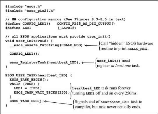
While the code and the functionality provided in Figure 14.9 is not very exciting, it does show the basic structure found in all ESOS applications. The hardware configuration in user_init() should be familiar to you by now. Since the user_init() function is called before the ESOS scheduler and the ESOS serial communications service are completely up and running, the code in user_init() calls a hidden ESOS function __esos_unsafe_PutString to print the HELLO_MSG string to the serial port and your terminal screen. In general, user application code should never call hidden ESOS functions, which are those functions prepended with double underscores. This is one of the few exceptions if you want to print a string before the ESOS is fully initialized. Before ending, user_init() registers the sole user task heartbeat_LED.
The code of user task heartbeat_LED is very simple. The task immediately enters a while (TRUE) loop, where TRUE is a constant defined in the ESOS header files for your convenience. The infinite loop in heartbeat_LED simply complements the state of the LED1, then the task yields control for 250 ESOS system ticks, or 250 ms, by calling ESOS_TASK_WAIT_TICKS(250). This is repeated until the system is powered down or reset. The period of the flashing LED is a little more than 500 ms because each call to ESOS_TASK_WAIT_TICKS(250) is slightly more than 250 ms. The task heartbeat_LED resumes at its next execution opportunity after 250 ms has elapsed.
Now that you have seen the fundamental task management interfaces provided by ESOS, we need to reiterate a few key requirements for applications written in ESOS. Since user tasks must cooperate for a functioning system, it is imperative that user tasks and program statements strictly follow these rules.
![]() ESOS has complete control over the hardware that creates the ESOS system tick. User code shall not manipulate the hardware or its software structures that create the ESOS system tick in any way. In the PIC24 μC port of ESOS, the system tick is created by Timer1.
ESOS has complete control over the hardware that creates the ESOS system tick. User code shall not manipulate the hardware or its software structures that create the ESOS system tick in any way. In the PIC24 μC port of ESOS, the system tick is created by Timer1.
![]() User code shall not directly manipulate any hardware interrupt enables or interrupt flags. All modifications to these bits shall be done through ESOS-provided functions for interrupt services. ESOS must be kept aware of the status of these bits, and does so through the interrupt service functions that ESOS provides to user.
User code shall not directly manipulate any hardware interrupt enables or interrupt flags. All modifications to these bits shall be done through ESOS-provided functions for interrupt services. ESOS must be kept aware of the status of these bits, and does so through the interrupt service functions that ESOS provides to user.
![]() User tasks shall not have code that executes for any appreciable duration. If a task has functionality that executes an unknown, arbitrary, or lengthy period of time, the user task should be constructed to wait or yield in some way so that other tasks can get focus and execute. (Some ESOS services are implemented as hidden tasks called by the scheduler in a similar manner as the user tasks. If user tasks monopolize the processor, some ESOS services will not execute properly.)
User tasks shall not have code that executes for any appreciable duration. If a task has functionality that executes an unknown, arbitrary, or lengthy period of time, the user task should be constructed to wait or yield in some way so that other tasks can get focus and execute. (Some ESOS services are implemented as hidden tasks called by the scheduler in a similar manner as the user tasks. If user tasks monopolize the processor, some ESOS services will not execute properly.)
![]() The ESOS task functions
The ESOS task functions ESOS_TASK_WAIT_UNTIL(cond) and ESOS_TASK_WAIT_WHILE(cond) statements yield control only if the associated condition fails. However, if the associated condition is asserted at the first call, the task does not yield. User tasks should have at least one yielding statement that is guaranteed to yield under all circumstances to prevent monopolizing the processor.
![]() User task variables that are required across any wait or yield statement must be declared
User task variables that are required across any wait or yield statement must be declared static. If the user task variable is not declared static, the value of the variable after the wait/yield is unpredictable.
![]() Users shall not use the C language
Users shall not use the C language switch statement constructs across wait or yield functions. The protothread library used to implement ESOS user tasks is based on Duff’s Device, which is, in reality, a switch statement. It is highly recommended that you avoid the switch constructs completely. Use if-else constructs instead. The if-else construct is safe in all ESOS contexts.
ESOS Communication Services
As you’ve seen in almost every code example since Chapter 8, serial communications provide a valuable link between the PIC24 μC and the outside world. Because serial communications are so common in embedded systems, ESOS provides communication services to its applications. ESOS initializes the communications hardware, manages the transmission and reception of data, and provides applications with a higher-level programming interface for sending and receiving a variety of data types. ESOS provides communication services for synchronous communication protocols using the PIC24 μC’s SPI and I2C peripherals, and asynchronous communications with the PIC24 μC’s UART peripheral. All three communication services are similar. Because asynchronous communications via the UART are very useful for demonstration of and interaction with these programs, this section concentrates on that particular part of the ESOS communication service. Once you understand the structure of the asynchronous communication service provided by ESOS, the synchronous services become straightforward in terms of understanding and usage. All communication services provided by ESOS are well-documented in the source code files and in electronic documentation. You’re encouraged to peruse these resources further.
Asynchronous communications on the PIC24 μC are readily done by using the provided hardware UART. The low-pin-count members of the PIC24 μC family have only UART1, so ESOS uses UART1 to implement the asynchronous communication service. Any additional hardware UARTs provided by the PIC24 μC are available for use by user code. The version of ESOS included with this book is written to use UART1 for the ESOS communication service. The ESOS code is easily modified to use other UARTs, if they exist on the processor, for the serial communication service.
The easiest way to start understanding how to implement asynchronous communications in ESOS is by example. One of the simplest examples of asynchronous communications is the echo program in Figure 8.7. This program accepts serial data from UART1, increments each character by one, and sends the incremented character back via UART1. Figure 14.10 gives the ESOS implementation of the echo program.
The task heartbeat_LED remains in Figure 14.10, and is unchanged from Figure 14.9. The only change in the user-provided function user_init() is the registration of another task echo, which is discussed shortly. If you compare the code in Figure 14.10 with the program in Figure 8.7, it appears that the ESOS version does not configure the UART. The UART initialization (see Figure 10.14), along with initialization of several other peripherals, is done by the ESOS system code before and after its call to user_init(). Furthermore, ESOS also provides all the code and performs all the housekeeping for managing UART interrupts (see Figures 10.18 and 10.20) and the incoming and outgoing communications software FIFO structures (see Figure 10.17). While the code in Figure 14.10 is compact, many more operations are being done behind the scenes by the ESOS system code, which are not seen. This, of course, is the purpose of the OS in the first place: to perform mundane or common operations.
Figure 14.10
C code for testing the serial link as an ESOS application
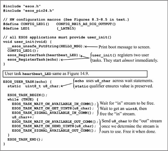
The work of echoing the serial data stream is done by the echo task in Figure 14.10. Since the echo task never stops its duties, the task is coded with the now familiar while (TRUE) loop structure. At the start of each pass through the loop, the echo task calls ESOS_TASK_WAIT_ON_AVAILABLE_IN_COMM(), which requires explanation.
ESOS is a multitasking OS. Since the UART is a single resource that is potentially used by more than one task, and these tasks can potentially execute simultaneously, ESOS must provide a means of ensuring orderly access to this resource. ESOS implements a mutual exclusion (mutex) semaphore for the incoming serial data stream via the two functions ESOS_TASK_WAIT_ON_AVAILABLE_IN_COMM() and ESOS_TASK_SIGNAL_AVAILABLE_IN_COMM(). All access to the incoming data stream should be bracketed by calls to these two functions. Truthfully, this mutex semaphore is not strictly required in Figure 14.10 since the echo task is the only one trying to access the UART. However, it is good practice to include the call to the mutex semaphore, as other tasks that use the UART may be added at a later time.
After the echo task acquires permission to access the serial incoming data by calling ESOS_TASK_WAIT_ON_AVAILABLE_IN_COMM(), echo asks the communications service to return the next uint8_t data from its software FIFO. There is the potential for the data to not be present or ready to read in the ESOS communication FIFOs. If the data is not ready, the echo task would be blocked from continuing execution. Therefore, the call to get data from the communications service is implemented as ESOS_TASK_WAIT_ON_GET_UINT8(u8_char). If the data is not available for your use, the echo task yields the CPU back to the ESOS scheduler so that other tasks, such as heartbeat_LED, can execute. The scheduler returns focus back to echo when the requested UART data is ready. After the call to ESOS_TASK_WAIT_ON_GET_UINT8(u8_char), the u8_char variable contains the desired data and execution can continue. The echo task then signals to ESOS and the other tasks that echo is no longer accessing the incoming serial data stream. The echo task can now increment u8_char, and then the result is placed in ESOS’s outgoing serial communications stream in the same manner as reading the incoming data stream. The outgoing serial data stream is also a single hardware resource desired by multiple multitasking tasks and must have mutex access via ESOS_TASK_WAIT_ON_AVAILABLE _OUT_COMM() and ESOS_TASK_SIGNAL_AVAILABLE_OUT_COMM(). Finally, there is the potential for the outgoing data software FIFO in ESOS to be full, which would block any writes to the FIFO. Therefore, tasks need to write data to ESOS communications services via task waiting calls such as ESOS_TASK_WAIT_ON _SEND_UINT8(u8_char).
Unsigned bytes or characters are not the only data types that user applications need to send and receive. ESOS communications provide functions to send and receive a variety of data types. Figure 14.11 shows a summary of the available functions. Each of these calls has the potential for the calling task to lose focus if the data is not yet ready in the ESOS communication system. The functions in Figure 14.11 work fundamentally the same as the functions in Figure 14.10. You are encouraged to explore these additional functions in your own programs.
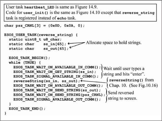
The echo task in Figure 14.10 reads the incoming characters one by one. Each call to ESOS_TASK_WAIT _ON_GET_UINT8() is surrounded by the ESOS_TASK_WAIT_ON_AVAILABLE_IN_COMM() and ESOS_TASK_SIGNAL_ AVAILABLE_IN_COMM() calls to the built-in ESOS mutex semaphore. Likewise, the echoed characters are sent back to the screen one by one with mutex semaphore synchronization. This format works fine but introduces a significant overhead in the repeated wait-and-signal operations on the UART mutex semaphores. A more efficient way is to acquire control of the incoming serial data stream and read in a number of characters before relinquishing control of the stream. Then, the task could process many characters at a time before trying to acquire the outgoing data stream. Figure 14.12 shows an application that takes this approach in recreating the string reversal program of Figure 10.16. Furthermore, the code in Figure 14.12 demonstrates how a task can call a user-provided helper function to do some common task. The function reverseString() was discussed in Chapter 10. Figure 14.12 shows only the code for task reverse_string. The remainder of the application code is identical to the code found in Figure 14.10.
Figure 14.11
ESOS communication service functions to send and receive different data types
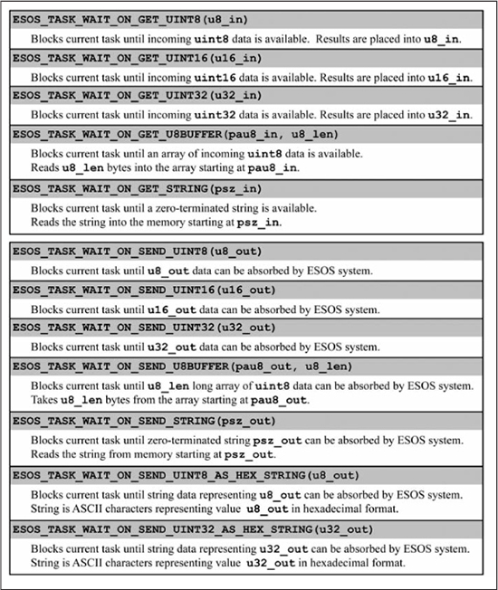
Figure 14.12
ESOS code to reverse a string
ESOS Timer Services
The PIC24 μC hardware timers were fully explored in Chapter 12. As you saw in that chapter, timers are powerful tools in typical embedded systems applications. Hardware timers are a μC resource typically in short supply. The dsPIC33EP128GP502 has five hardware timers. One timer, Timer1, is claimed by the ESOS system software to implement the ESOS system tick, leaving you with only four hardware timers. ESOS provides a software timer service to its applications. ESOS timers are software timers based on the ESOS system tick. As such, they are not suitable for timing periods that approach or are shorter than the ESOS system tick of 1 ms. However, if a task needs a timer for periods longer than the system tick, ESOS software timers are ideal candidates.
In general, user applications should not concern themselves with the implementation details of the host OS. In fact, it is usually a bad idea. The OS designers should be free to change the implementation of the OS without breaking the application code that they host. As long as the applications write software that uses the OS’s public application programming interface (API), the code composing the functions of the API can change. However, it is useful to know the implementation of the ESOS timer service in order to understand its proper use. The ESOS system tick is created in the ISR of hardware Timer1 that is configured to interrupt the normal processing every 1.0 ms. After the ESOS system tick variable is incremented, the ESOS timer service examines the software timers being used by the application. If ESOS detects that a software timer has expired, the ESOS timer service runs the software timer’s associated callback function, a user-provided function that ESOS calls at a time that it determines is appropriate. The user provides this callback function to ESOS when the user requests a software timer from the ESOS timer service. The key point is that your software timer callback functions run within the Timer1 ISR. Software timer callback functions must be extremely short or system performance is negatively impacted. Excessive computations in software timer callback functions can cause the system to miss system ticks, leading to a failure of the entire system.
Let’s explore the ESOS timer service by returning to the example code in Figure 14.10. While the code in Figure 14.10 works perfectly well, let’s change the heartbeat_LED task to use the ESOS timer service instead of being an ESOS user task. The only computation performed in the heartbeat_LED task is to complement LED1. With such low computation requirements, the heartbeat_LED task is an ideal candidate for implementation as a software timer from the ESOS timer service. Figure 14.13 shows the code to echo incremented characters with the flashing LED implemented as an ESOS software timer.
Figure 14.13
ESOS code using software timer to flash LED
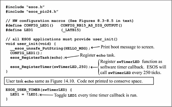
The user_init() routine in Figure 14.13 is not very different from the earlier example in Figure 14.10. Instead of registering the heartbeat_LED task, user_init() registers a software timer named swTimerLED() with a timeout value of 250 ms by calling esos_RegisterTimer(swTimerLED, 250). The timer itself is declared and the callback code is provided by the macro ESOS_USER_TIMER(swTimerLED). The callback code itself is simple C code to complement LED1. Figure 14.14 shows the functions available to manage your software timers.
Figure 14.14
Functions provided by the ESOS timer services
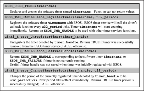
The ESOS timer service allows users to create up to 16 software timers. All 16 timers are queried at each system tick to determine the timers that have expired. Expired timers are reset and their callback functions are executed. Remember that software timer callback functions are executed within the context of the ESOS system tick ISR. Your software time callback functions are effectively ISRs, and should be designed with this in mind. If you were to create 16 different software timers and all 16 timers expired at the same tick value, then the ESOS system tick ISR would call all 16 of your callback functions, one after the other. If the execution of all 16 callback functions took a long time, it is possible that the ESOS system would miss the next system tick interrupt. This is another good reason why your software timer callback functions need to be short and efficient.
The code in Figure 14.13 should behave identically to the code in Figure 14.10. The only difference is that the period of the flashing LED in Figure 14.13 is more accurate than in Figure 14.10. The software timers are called from the ESOS system tick ISR, which runs at a high ISR priority level. The period of the flashing LED in Figure 14.10 is affected by relying on the other tasks to give up processor focus. Of course, the exact period of a flashing LED is usually not significant, and the period inaccuracies in Figure 14.10 are acceptable. Applications requiring more accurate time duration should consider software timers. Applications requiring very accurate or very short time durations should use PIC24 μC hardware timers and their associated interrupts. The next section explores the ESOS semaphore services.
ESOS Semaphore Services
As you saw at the beginning of this chapter, tasks running in multitasking OSes require synchronization. User tasks in ESOS are no different. There will be many times when your user tasks will want to signal, rendezvous, or have mutually exclusive execution with other tasks. ESOS provides a basic set of services for managing semaphores. This section discusses the semaphore services that ESOS provides and examines two examples of semaphores in action.
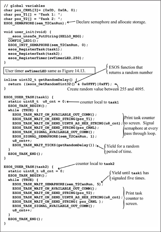
The first example application has two tasks where one task runs every fifth time that the other task runs. This scenario requires the more frequently executing task to signal a semaphore to the other task on every fifth run. This signal enables the second task, which is waiting for the semaphore to execute. Figure 14.15 shows the code that implements this example scenario.
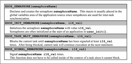
The code in Figure 14.15 creates a semaphore sem_T2CanRun in the global variable scope of the application with the macro ESOS_SEMAPHORE(sem_T2CanRun). Since semaphores are used for inter-task communications, the semaphore itself must be global in scope so that both tasks can access it. The declaration macro creates the semaphore only as a program variable and instructs the compiler on how to store the data in memory. The declaration macro ESOS_SEMAPHORE() does not give the semaphore any initial value. The name inside the parentheses is the name by which the semaphore will be known in the program. The user_init() routine initializes the semaphore value to zero with ESOS_INIT_SEMAPHORE(sem_T2CanRun, 0).
The functionality of the task1 is easy to determine from the code in Figure 14.15. The task task1 runs forever incrementing a local counter u8_cnt on each pass through its loop. During each pass, task1 prints an identifier to the screen along with the current counter value, and signals the sem_T2CanRun semaphore by calling ESOS_SIGNAL_SEMAPHORE(sem_T2CanRun, 1). At the conclusion of each pass through the loop, task1 yields the processor for a random number of ticks, which is determined by the user-provided function getRandomDelay(). The function getRandomDelay() calls an ESOS-provided function esos_GetRandomUint32(), which returns a pseudo-random 32-bit number between one and 232-1. The function getRandomDelay() limits the numbers from this very large range to a maximum value of 4095 by AND-ing with 0xFFF and to a minimum value of 255 by OR-ing 0xFF. Thus, task1 will yield the processor for only approximately 0.26 to 4.1 seconds when it calls ESOS_TASK_WAIT_TICKS(getRandomDelay()).
The code for task2 is similar to that of task1. The user task task2 also has an infinite loop that prints an identifier and its current local counter value. The difference between task2 and task1 is that task2 does not execute its loop code until the semaphore sem_T2CanRun has been signaled five times by task1. The loop in task2 yields until the five signals are performed by calling ESOS_TASK_WAIT_SEMAPHORE (sem_T2CanRun, 5). Of course, five signals to sem_T2CanRun means that task1 has progressed through its loop five times as required by the design specification.
Figure 14.15
ESOS code demonstrating signaling with semaphores
This simple example of signaling with semaphores uses all of the functions in the semaphore services provided by ESOS. Figure 14.16 shows a summary of the functions in the ESOS semaphore service. With these four semaphore functions, many synchronization problems can be solved. Another short ESOS semaphore example follows.
Figure 14.16
Functions provided by the ESOS semaphore services
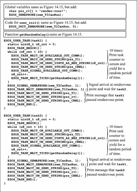
Tasks in a multitasking OS often need to rendezvous at a point in the code before they all proceed. Semaphores provided by ESOS can easily implement rendezvous synchronization. Figure 14.17 shows an example application where two tasks must rendezvous before they proceed. The two tasks task1 and task2 are identical in their function. Each task maintains a local task counter u8_cnt that is incremented by one each time the task proceeds through its loop. Each pass prints an identifying message to the screen along with the current value of u8_cnt. Before looping back, each task yields control for a random length of time. Both task1 and task2 perform these operations 10 times. Neither task is allowed to proceed until both tasks have completed their 10 passes through the loop. After task1 and task2 have met at the rendezvous point, each task prints a final message before the tasks end.
With the tasks yielding for a random length of time, the order in which the tasks reach the rendezvous point is unknown. However, the random value returned by esos_GetRandomUint32() is generated by a pseudo-random number generator so the sequence of random numbers is the same each time the application is executed. Generating a good sequence of random numbers is much harder than it might appear. The best sequences have some truly unpredictable component. The sequence of random numbers generated by ESOS is less predictable when the generator is seeded with a number that changes with each execution of the code. The random number generator in ESOS can be seeded with the esos_SetRandomUint32Seed() function.
Figure 14.17
ESOS code demonstrating rendezvous synchronization with semaphores
Figures 14.15 and 14.17 show examples of signaling and rendezvous semaphores, respectively. Mutex semaphores can be readily implemented with the semaphore functions in Figure 14.16. The details of this are left as a homework exercise. Mutex semaphores are also easy to implement using the user flags and associated functions provided by ESOS. These functions are described in a subsequent section.
ESOS Messaging Services
Semaphores provide tasks with a convenient way to coordinate or synchronize their operation. However, often tasks also need to communicate data simultaneously with synchronization. Messages are a convenient way for tasks to send information to other tasks. Reception of the mail message itself also provides the requisite signaling for task coordination. ESOS provides a basic set of services for tasks to create, send, and receive messages. This section discusses the messaging services that ESOS provides and examines an example of messaging in action.
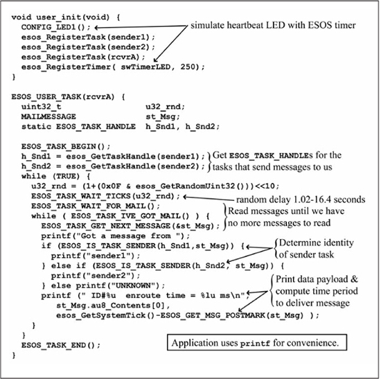
The messaging example application in Figure 14.18 and 14.19 has three concurrently running tasks. Two of the tasks, sender1 and sender2, exist solely to create mail messages with a simple 8-bit payload—an incrementing message counter to identify the messages uniquely. These mail messages are sent the third task rcvrA. The two message sending tasks sender1 and sender2 differ slightly. The task sender1 sends messages to task rcvrA without delivery confirmation. Also, if the receiving task rcvrA does not have room in its inbox for the message, then task sender1 will continue execution doing some other useful computations. The second sending task sender2 also sends messages to the receiving task rcvrA. However, sender2 will not send a message if the task rcvrA does not have room available in its mailbox. In other words, if task rcvrA’s mailbox is full, then task sender2 is blocked. Furthermore, task sender2 randomly selects a mail message to be sent with delivery confirmation. Upon sending a mail message of this type, task sender2 is blocked until destination task rcvrA reads that message. Notice in Figure 14.19 that the receiver task rcvrA is constructed to check and read its mail more slowly than the sender tasks sender1 and sender2 send messages to demonstrate the blocking nature of full task mailboxes.
Figure 14.18
ESOS code demonstrating messaging (part 1)
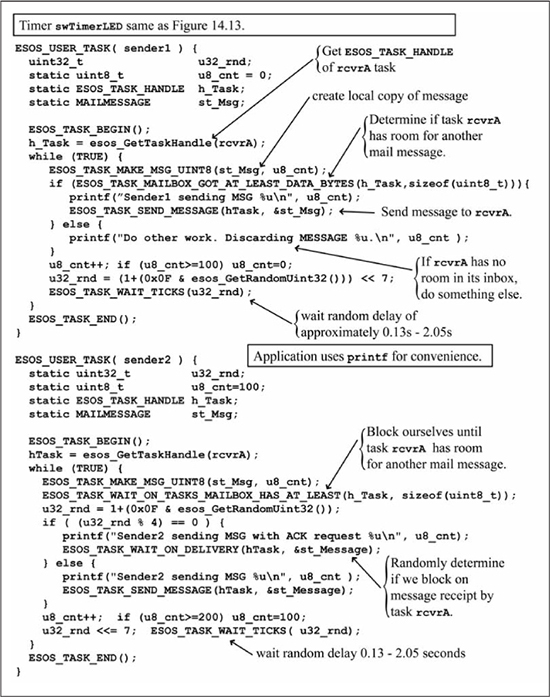
Figure 14.19
ESOS code demonstrating messaging (part 2)
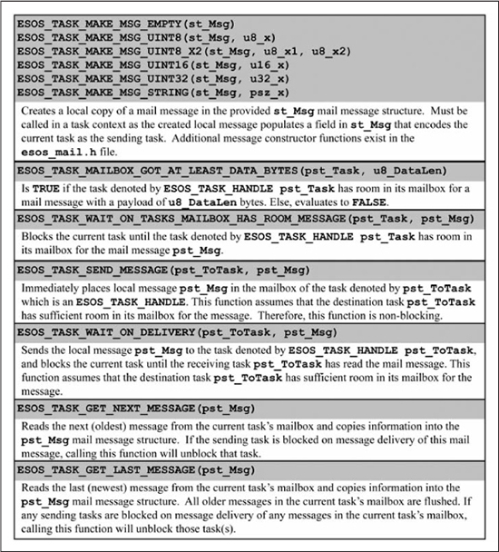
This simple example of messaging in Figure 14.18 and 14.19 uses nearly all of the functions in the messaging services provided by ESOS. Figure 14.20 shows a summary of the primary functions in the ESOS messaging service. Additional ESOS message service helper macros and functions are available. You are strongly encouraged to delve deeper into the capabilities of this powerful ESOS service by studying the files esos_mail.h and esos_mail.c in the provided software library.
Figure 14.20
Select functions provided by the ESOS messaging service
This section concludes with a modification to the messaging example application in Figures 14.18 and 14.19. In its execution loop, the task rcvrA in Figure 14.19 reads every message in its inbox in the order in which they were received by calling the ESOS messaging function ESOS_TASK_GET_NEXT_MESSAGE(). Often, embedded system tasks are only interested in the most recent data sample. Older data values are simply not useful. The code in Figure 14.21 shows a new message receiver task rcvrD that only processes the newest mail message through the use of the ESOS messaging service function ESOS_TASK_GET_LAST_MESSAGE(). This function will read the most recent mail message from the current task’s mailbox and discard all older messages.
Figure 14.21
ESOS application of reading only the newest task message
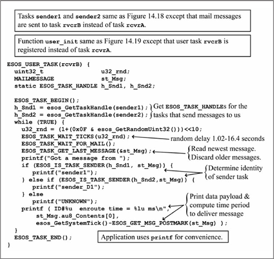
The example code in Figures 14.18, 14.19, and 14.21 provide two examples of how the ESOS messaging service can be used. The combination of task coordination through sending and receiving messages combined with the delivery of data, or information, in those messages makes the messaging service very powerful. You are encouraged to learn about all the additional functions of the ESOS messaging service by reading the provided software library. A section later in this chapter will use the ESOS messaging service to create a more practical application that communicates with an external sensor.
ESOS User Flags
In a multitasking OS, user tasks are often coded as if they were running on the processor alone. The only indication in the code that other tasks or operations are ongoing are the occasional yield/wait statements and code that signals other tasks and functions via semaphores and simple binary flags.
In addition to providing semaphore services, ESOS also provides user applications with 16 global flags. These user flags can be used for general binary state storage within a task or function, as a signal between functions, or for inter-task synchronization as a mutex semaphore. Figure 14.22 contains a summary of the user flag functions provided by ESOS.
Figure 14.22
Functions provided by the ESOS flag service
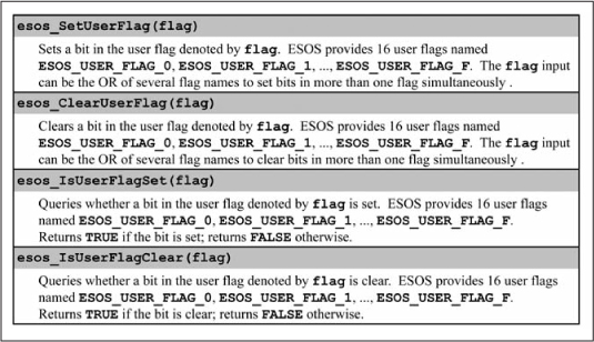
The user flags provided by ESOS allow for easy creation of binary semaphores, a semaphore than can only take on the values 0 and 1. Listing 14.2 shows a code snippet that creates a binary semaphore using the ESOS flag service. Notice how the user should #define an insightful name such as LIGHTS_ARE_ON to replace the generic user flag name ESOS_USER_FLAG_3.
Listing 14.2: Binary Semaphores Created with User Flags
// create an application-specific name for the user flag
#define LIGHTS_ARE_ON             ESOS_USER_FLAG_3
// define semaphore macros that user tasks can use
#define SIGNAL_LIGHTS_ON_MUTEX      esos_SetUserFlag(LIGHTS_ARE_ON)
#define WAIT_LIGHTS_ON_MUTEX        do {
     esos_ClearUserFlag(LIGHTS_ARE_ON);
     ESOS_TASK_WAIT_UNTIL(esos_IsUserFlagSet(LIGHTS_ARE_ON));} while (0)
The user flags provided in Figure 14.22 are global; that is, they can be assessed and modified in any scope. The global nature of these flags can be a bit dangerous but makes these flags very useful for inter-function and inter-task signaling. In fact, ESOS maintains a private set of flags structured just as the user flags in Figure 14.22 for its own internal use. The commands ESOS_TASK_WAIT_ON_AVAILABLE_IN_COMM(), ESOS_TASK_SIGNAL_AVAILABLE_IN_COMM(), ESOS_TASK_WAIT_ON_AVAILABLE_OUT_COMM(), and ESOS_TASK_SIGNAL_AVAILABLE_OUT_COMM() in the ESOS communication service are implemented with these private ESOS system flags and macros just as those in Listing 14.2.
ESOS Child Tasks
In Figure 14.12, you saw how the task reverse_string could call a helper function reverseString to perform some simple operation on its behalf. You would typically factor your code in this way when the helper function performs an operation that other tasks or code would also need performed. The helper function allows code to be more easily read by separating logical operations and more easily maintained by having only one copy of code in an application. Notice that the helper function reverseString in Figure 14.12 is given all of the information it needs, the entire string sz_in, to complete its task.
Now, consider the scenario where some task wanted to use a helper function, but that helper function could not complete its operation until some event occurred. Your application code written in the earlier chapters would have probably contained a line of code such as while (!event); to cause the helper function to wait. This approach would not be acceptable in ESOS. The task would get the CPU focus, and call the helper function that would then wait for the event to occur. At best, other tasks would be blocked from execution until the event was triggered externally. In the worst case, the event itself is to be created by a task that could never do so because that task is blocked by the task calling the helper function. What you need to solve the problem is a helper function that can yield or wait just like a task.
The first thought is to simply place an ESOS wait/yield statement like string ESOS_TASK_WAIT_UNTIL() in the helper function. This solution does not work because ESOS tasks are implemented through repeated function calls, by the ESOS scheduler, to a function (your user task code) that uses local continuations (Duff’s Device) to maintain your task’s state. Simply put, the helper function your task calls is a different function from your user task that has no concept of what a task state even is. What you need is some kind of ESOS task that can yield and wait, such as an ESOS_USER_TASK, but can be called by an ESOS_USER_TASK instead of the ESOS scheduler. ESOS provides just such a solution: a special kind of task called an ESOS_CHILD_TASK.
The discussion of ESOS_CHILD_TASK, or simply, child tasks, sometimes refers to tasks of the type ESOS_USER_TASK as parent tasks. Just as with humans, where every human is not a parent until he or she has a child, not every ESOS_USER_TASK is a parent task. Only an ESOS_USER_TASK that creates a child task can be called a parent to that child task. A child task, declared as type ESOS_CHILD_TASK, is created by and called by its parent task, not by the ESOS scheduler. When a parent task creates the child task, an operation ESOS calls spawning, the parent task is blocked until the child task ends. This simple fact is very important as it means:
![]() All child tasks must eventually end, or their parent is forever blocked from executing.
All child tasks must eventually end, or their parent is forever blocked from executing.
![]() The child task, in practice, takes the parent task’s place in the ESOS scheduler.
The child task, in practice, takes the parent task’s place in the ESOS scheduler.
Child tasks have one more very big, and useful, difference from normal user tasks: input arguments. Recall that the parent tasks are called by the ESOS scheduler, so input arguments are not possible.
Since child tasks are spawned, or called, by parent tasks, the parent task has the opportunity to create the child task and pass it arguments.
The best way to learn about child tasks is to see one in action. Figures 14.23 and 14.24 show the code for another version of the echo application. In the previous versions (see Figures 8.7 and 14.10), characters were incremented by one and echoed back. In this version of echo, the user is prompted to type a single number that is to be used as the increment value. The input can take on the values between zero and nine.
Figure 14.23
ESOS code to echo characters with variable increment (part 1)
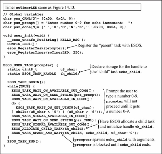
The code in Figure 14.23 to initialize the hardware and software timer for the flashing LED should be very familiar by now. The new concept in Figure 14.23 deals with how prompter, which is an ESOS_USER_TASK, spawns (gives birth) to echo_child, which is an ESOS_CHILD_TASK. The first difference is that prompter declares some static storage space for a variable th_child, which is of type ESOS_TASK_HANDLE. Near the bottom of Figure 14.23, prompter calls ESOS_ALLOCATE_CHILD_TASK(th_child) that has ESOS allocate a child task and assign th_child to point to the newly created child task. At this point, a child task does not yet exist on its own. You could say that prompter is “pregnant.” The child task storage has been created and everything is properly initialized, but the child task echo_child is not yet functioning. A user task becomes a parent when it gives birth to, or spawns, a child task. Spawning is done by the call to ESOS_TASK_SPAWN_AND_WAIT(). The first two arguments to ESOS_TASK_SPAWN_AND_WAIT(), the handle to the child task and the name of the child task itself, are required. Any arguments that the parent task desires to give the child task can be added after the two required arguments. In the example in Figure 14.23, the parent task prompter passes the child task echo_child the number by which characters should be incremented.
Figure 14.24
ESOS code to echo characters with variable increment (part 2)
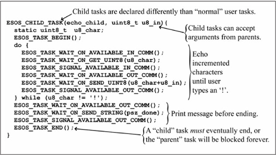
The child task echo_child looks much like all of the other ESOS_USER_TASKs you’ve seen in this chapter. The major differences are that echo_child is declared as an ESOS_CHILD_TASK instead of ESOS_USER_TASK, and echo_child is passed an uint8_t input argument called u8_in. Child tasks that do not have any input arguments from their parent are identical to ESOS_USER_TASKs, apart from the different declaration statement.
There are a couple more points to reiterate about child tasks: they must eventually execute their ESOS_TASK_END statement and they cannot be active with two parents at the same time. Recall that parent tasks are blocked until their child task ends. If the child task does not end, the parent task is blocked forever. While this scenario is allowed and possibly useful, it will probably be rare. The usual behavior is that a child task executes an often-used operation on behalf of its parent(s) and then ends so that the parent may continue executing. A child task can be spawned by different parent tasks; however, the child task cannot be active with two parents at the same time. The fundamental reason for this is that a child task maintains its current state and cannot be in two different states at the same time. The latter would be the result if two parents both actively spawned the same child task at the same time.
Child tasks give the user a powerful tool to collect commonly used code that must yield/wait into one location. In fact, you have been using child tasks since the beginning of this chapter. The majority of ESOS commands in the ESOS communications services are actually disguised spawns of child tasks. When your task, which is an ESOS_USER_TASK, calls ESOS_TASK_WAIT_ON_GET_UINT8(), your task becomes a parent task and waits for the child task to complete. The child task ends when it is successful in getting the uint8_t from the ESOS communications FIFO. When the child task ends, your parent task continues execution and makes use of the newly acquired uint8_t data. Child tasks make your ESOS applications easier to write, understand, and maintain. ESOS itself would not exist without them.
ESOS Interrupt Services
As you saw in Chapter 9, interrupts in embedded systems are used to provide a rapid response to deadline-driven peripherals. With the context switching between the code in main() and the ISRs, an embedded system using interrupts appears to perform more than one task at a time. While a multitasking OS like ESOS is a more flexible and maintainable way to allow the processor to seemingly perform more than one task at a time, interrupts still have a place in multitasking OS design when peripherals demand quick response to a request. ESOS uses interrupts internally to implement the system tick and the software timers, and to manage the asynchronous serial communication system. The hardware registers and the interrupts that create these services are not to be manipulated by user applications; however, ESOS provides a service for initializing and using the other hardware interrupts provided by the processor. This section describes the ESOS interrupt service.
So that ESOS can efficiently manage the processor, its timing, and resources, ESOS requires that it be kept aware of the processor operations at all times. On rare occasions, ESOS may need to temporarily disable certain interrupts in order to configure the processor, execute critical code, or maintain accurate timing. If ESOS is to disable interrupts and restore them afterward, ESOS must have a mechanism by which it can be apprised of interrupt state: whether the interrupt is being used, what code services the interrupt, and the current state of the interrupt. While the user is free to use any hardware interrupt not already being used by ESOS internally, the user must control and manage these interrupts through functions provided by the ESOS interrupt service. Figures 14.25 and 14.26 show the ESOS application code to recreate the pulse-width measurement application in Figures 12.4 and 12.5.
Figure 14.25
ESOS code to measure pulse widths with user interrupts (part 1)
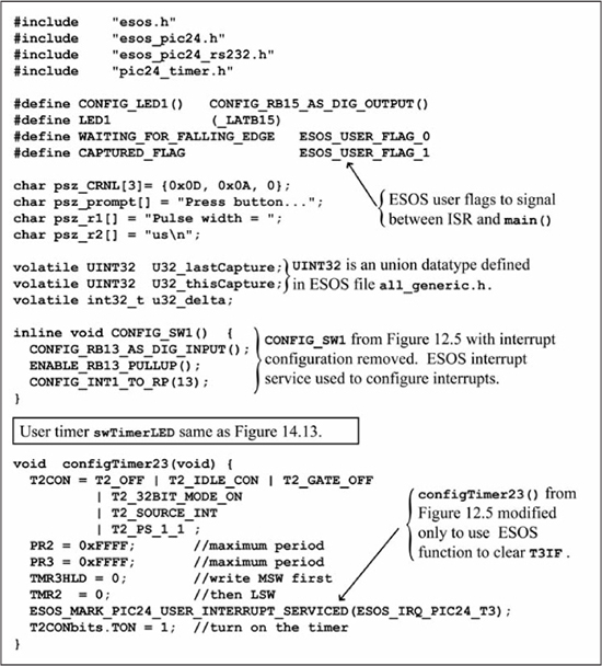
The code structure in Figures 14.25 and 14.26 is identical to the code in Figures 12.4 and 12.5. The major changes are that Figure 12.5’s code in main() is now performed with a user task called task1, and all INT1 operations are performed through functions provided by ESOS interrupt services. The code in Figure 14.25 should be largely self-explanatory as it contains the typical macro definitions and global variable declarations. The ISR for the external interrupt INT1 signals the code in main() through ESOS-provided user flags. To aid readability and maintainability of the code, the code defines its own names, WAITING_FOR_FALLING_EDGE and CAPTURED_FLAG, for the ESOS user flags. The final item to note in Figure 14.25 is that configTimer23() uses the ESOS interrupt service function ESOS_MARK_PIC24_USER_INTERRUPT_SERVICED() to clear the T3IF bit instead of clearing it directly. Thus, ESOS is informed of the state of the T3 interrupt.
Figure 14.26
ESOS code to measure pulse widths with user interrupts (part 2)
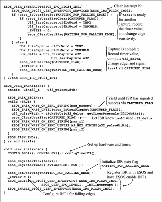
In Figure 14.26, the code used to service the INT1 interrupt is declared with ESOS_USER_INTERRUPT(ESOS_IRQ_PIC24_INT1). All ISRs should be declared as ESOS_USER_INTERRUPT with the appropriate argument. ESOS provided arguments for all PIC24 hardware interrupts available to the user. The ISR is registered and enabled in user_init() with the ESOS functions ESOS_REGISTER _PIC24_USER_INTERRUPT(ESOS_IRQ_PIC24_INT1) and ESOS_ENABLE_PIC24_USER_INTERRUPT(ESOS_IRQ_PIC24_INT1). Apart from the ESOS interrupt service calls and the use of ESOS user flags, the ISR code in Figure 14.26 is the same as Figure 12.4. The functionality of Figure 12.5’s main() is performed by task1 in Figure 14.26.
ESOS provides a full set of functions for users to manage interrupts in their applications. Figure 14.27 shows the complete set of ESOS interrupt service functions. All user manipulation of interrupt registers should be done through these functions. The current implementation of ESOS interrupt services for the PIC24 family does not allow reregistration of interrupts; that is, a user interrupt cannot change the function that responds to the interrupt at run-time. This restriction may be removed in future versions of ESOS.
Figure 14.27
Functions provided by the ESOS interrupt service
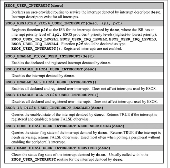
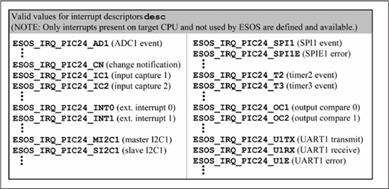
Working in conjunction with a multitasking OS like ESOS does not change the fact that interrupts are asynchronous interruptions of the normal code flow. Just as in Chapter 9, the ISRs or ESOS_USER_INTERRUPTs you write should be short and perform only the operations for which they are uniquely qualified. Once the ESOS_USER_INTERRUPT has done its function, the ESOS_USER_INTERRUPT should set a flag or signal a semaphore so that non-interrupt code can further process, display, copy, or otherwise continue the operation outside of the ISR context. Finally, the ESOS_USER_INTERRUPT is simply an ISR and, as such, ESOS_USER_INTERRUPTs cannot execute any of the ESOS task commands to wait or yield.
Design: Adding an ESOS Service for I2C
In general, communications with other devices have the potential to be delayed, slow, or even nonexistent. Using the hardware support library in Chapter 10, you may have had your PIC24 μC reset because the watchdog timer timed out due to a communication error or a problem with the other device. In the earlier chapters, your code is the only program running on the μC, so these resets may be tolerable. However, there are potentially many different operations being performed by your μC when it is running a multitasking OS. The watchdog reset of the μC because of a communications error with a target device is not desirable because of the havoc it creates in the other unrelated tasks. If a target communications device is not functioning, then it is most desirable for only the ESOS task trying to communicate to be adversely affected. This is exactly what happens in the ESOS asynchronous communication system. Tasks that attempt to communicate via the ESOS communication function calls are blocked until the desired communication takes place. Other unrelated tasks continue to function unaware of the problems.
The cooperative multitasking capability in ESOS provides the mechanism by which many functions can be accomplished. In the previous section, you saw the ESOS functions by which tasks can wait, yield, and communicate their intentions to the ESOS scheduler. You also saw how tasks can communicate with each other with semaphores and flags and create other tasks, by registering them or spawning child tasks. You were also introduced to the asynchronous communication services provided by ESOS. This service encapsulates the UART configuration and operation on the PIC24 μC family. The communication service is constructed with a collection of C language macros that create and spawn child tasks. These child tasks block the calling parent task until the child task accomplishes the job of getting or receiving data from the UART. You are encouraged to examine the structure of the ESOS asynchronous communication service by reading its source code. The members of the PIC24 μC family contain several other useful communications peripherals, such as the I2C and the SPI peripherals. As with asynchronous communications, the I2C and the SPI communication protocols also have the potential for delays, latency, or failure. ESOS applications need a way to use these protocols but gracefully handle delays or failure.
This section guides you through the creation of an ESOS service for I2C. Then, you will use this new service to recreate an application from Chapter 10. Creating an I2C service will use many features of ESOS and allow you to become better acquainted with ESOS organization. Furthermore, the asynchronous communication service is constructed in almost an identical fashion so you will learn better how the UART services work. Also, there may come a time when you need to create a custom service for your own ESOS applications. The methods described here can be your guide. Finally, ESOS services for SPI are included in the source code for the ESOS system and will not be covered here. A good understanding of the I2C service created in this section will help you to understand and use the ESOS SPI service.
I2C Operations Under ESOS
The I2C hardware support library introduced in Chapter 10 provides easy access to common I2C operations and transactions. Specifically, Figure 10.44 lists the I2C function calls when ESOS is not present. In general, the routines in Figure 10.44 cannot be used in ESOS applications because these routines block the processor during communication delays, and potentially reset the processor in the extreme case. You need to adapt the functions in Figure 10.44 to a new form that can be used in ESOS applications.
The I2C configuration routine configI2C1(uint16_t u16_FkHZ) in Figure 10.48 does not wait for some external operation to complete but simply configures the I2C peripheral registers in the PIC24 μC. Therefore, this function is compatible with ESOS unchanged. However, to avoid naming conflicts and keep the function names consistent, ESOS I2C services will name the configuration routine esos_pic24_configI2C1(uint16_t u16_FkHZ). Listing 14.3 shows the code for the configuration routine.
Listing 14.3: ESOS I2C Configuration
void esos_pic24_configI2C1(uint16_t u16_FkHZ) {
  uint16_t u16_temp;

  u16_temp = (FCY/1000L)/((uint16_t) u16_FkHZ);
  // Ignore gobbler pulse delay, which is device dependent and small.
  u16_temp = (u16_temp - 1);
  if (u16_temp > 511) u16_temp = 511; // SCL divider only uses 9 bits
  I2C1BRG = u16_temp; I2C1CONbits.I2CEN = 1;
}
Basic I2C operations performed with the Chapter 10 functions startI2C1(), stopI2C1(), restartI2C1(), and putI2C1() all have the potential to be blocked by abnormal conditions. Furthermore, these basic operations are used by many other functions to construct larger I2C transactions. In Chapter 10, these functions recorded their execution into an error string and enabled the watchdog to reset the processor in the event that the blocking state did not unblock in due time. These features are useful in the code in the earlier chapters but are not compatible with ESOS. The ESOS versions of these operations must simply instruct the task to wait until the appropriate I2C condition is met. Finally, these basic operations are used as building blocks for other more complex routines so a C language macro is most appropriate. Figure 14.28 shows the macros to implement the basic I2C operations of start, stop, restart, and put.
Figure 14.28
Basic I2C operation macros for ESOS
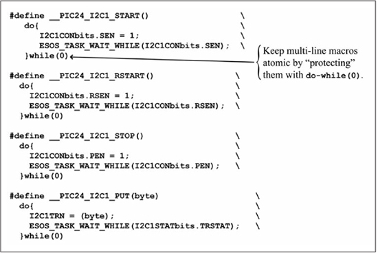
The basic operation getI2C() in Figure 10.49 is a bit more complicated. The process of getting a byte from the I2C bus requires that the function follow these steps:
1. Wait for an I2C bus idle condition
2. Enable the I2C receive bit
3. Wait for the received byte
4. Read the byte
5. Wait for an I2C bus idle condition
6. Acknowledge
7. Wait for acknowledge to complete
The preceding operation must occur in sequence, and each of the wait operations has the potential to be delayed or not occur. So, ESOS should provide a macro to implement the function to get one byte from the I2C bus. However, a macro is probably a bad idea for this operation as the macro will be quite long because it must perform at least seven distinct steps. Also, the means by which the C language compiler is used to implement the multitasking in ESOS prohibits the use of more than one ESOS wait/yield macro. The ESOS function to get a byte from I2C involves waiting, so it must be a task. However, this task will be called by other tasks. Therefore, ESOS provides this operation as a child task. Figure 14.29 shows the code for the child task to get a byte from the I2C bus. If you compare the code in Figure 14.29 with the code in Figure 10.49, you will find that the two functions are very similar.
Figure 14.29
ESOS I2C operation to read a byte from bus
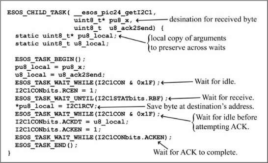
There are two key items to note in Figure 14.29. First, the arguments passed into __esos_pic24_getI2C1 are copied into local static variables to preserve their values across the wait statements. Second, the byte read from the I2C bus is placed at the address of the input argument since child tasks cannot return values to their caller. Other than changing the while (cond) waits in Figure 10.49 to ESOS-compatible ESOS_TASK_WAIT_WHILE(cond), the code in Figure 14.29 is largely unchanged. With the macro in Listing 14.3 and the code in Figures 14.28 and 14.29, you are now ready to implement a full I2C transaction to read and write data to a target device.
I2C Transactions Under ESOS
An I2C transaction consists of writing the target device’s address, reading or writing the correct amount of data, and responding with the appropriate acknowledgments. These I2C transactions will be called by other ESOS tasks, will have data passed into them, will pass data out of them, and will be blocked for an unknown period of time. Your only choice to satisfy all of these requirements is to implement the I2C transactions as child tasks, similar to __esos_pic24_getI2C1 in Figure 14.29.
The simplest transactions write data to a target device with I2C address u8_addr. Figure 14.30 shows the code to implement the child tasks to perform these transactions.
Like the child task __esos_pic24_getI2C1 in Figure 14.29, the transaction child tasks in Figure 14.30 must keep a static local copy of their arguments. Otherwise, the code in Figure 14.30 is very similar to the code in Figure 10.50.
Now that ESOS has created the child tasks in Figure 14.30 to write one, two, or an arbitrary number of bytes to a target device, other tasks can spawn these tasks. The parent tasks can declare an ESOS_TASK_HANDLE for the child tasks such as the code in Figure 14.23. A more efficient way is to have the ESOS_TASK_HANDLE automatically created by the C compiler when the I2C routines are included in a project. The file esos_pic24_i2c.c that contains the code described in this section simply declares the variable storage with the line struct stTask __stChildTaskI2C;. Whenever I2C is used in an ESOS application, the user can be assured that storage for a child task has been created.
Now, ESOS can further simplify the application designer’s job by providing some easy-to-use macros to implement an I2C transaction. Listing 14.4 shows macros for tasks to use in order to write data to a target I2C device. The file esos_pic24_i2c.h contains these macro definitions for your application use.
Listing 14.4: Macros to Perform ESOS I2C Write Transactions
#define ESOS_TASK_WAIT_ON_WRITE1I2C1(u8_addr, u8_d1)
      ESOS_TASK_SPAWN_AND_WAIT((ESOS_TASK_HANDLE)&__stChildTaskI2C,
      __esos_pic24_write1I2C1, (u8_addr), (u8_d1))
#define ESOS_TASK_WAIT_ON_WRITE2I2C1(u8_addr, u8_d1, u8_d2)
      ESOS_TASK_SPAWN_AND_WAIT((ESOS_TASK_HANDLE)&__stChildTaskI2C
      __esos_pic24_write2I2C1, (u8_addr), (u8_d1), (u8_d2))
#define ESOS_TASK_WAIT_ON_WRITENI2C1(u8_addr, pu8_d, u16_cnt)
      ESOS_TASK_SPAWN_AND_WAIT((ESOS_TASK_HANDLE)&__stChildTaskI2C,
      __esos_pic24_writeNI2C1, (u8_addr), (pu8_d), (u16_cnt))
Figure 14.30
ESOS child tasks to write data to a target I2C device
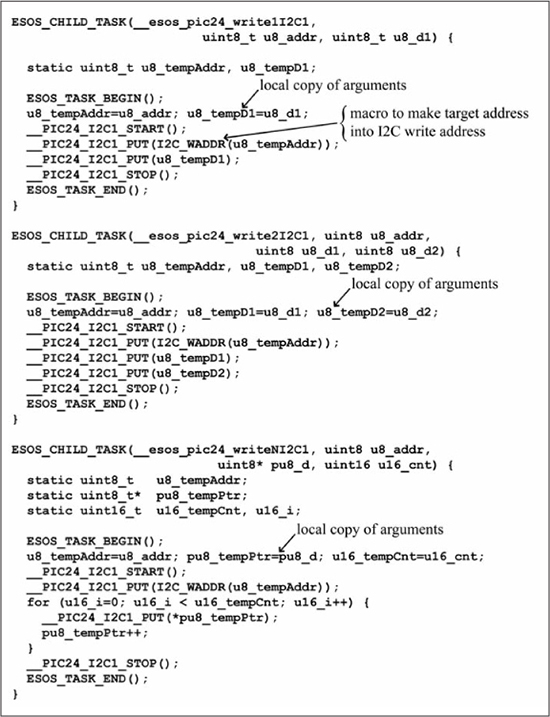
Recall that ESOS created a child task __esos_pic24_getI2C1 to read a byte from the I2C bus in Figure 14.29. This child task will be called by child tasks that perform the full I2C read transactions. Therefore, it would be useful to have a macro such as those in Listing 14.4 to facilitate using the child task __esos_pic24_getI2C1 in Figure 14.29. Also, since the task __esos_pic24_getI2C1 will be called quite often, ESOS can declare a task storage structure for it in esos_pic24_i2c.c with struct stTask __stGrandChildTaskI2C;. Listing 14.5 shows the macro used to simplify the calls to the child task __esos_pic24_getI2C1.
Listing 14.5: Macros to Spawn Child Task to Read a Byte from the I2C Bus
#define ESOS_TASK_WAIT_ON_GETI2C1(pu8_get, u8_ack2Send)
   ESOS_TASK_SPAWN_AND_WAIT((ESOS_TASK_HANDLE)&__stGrandChildTaskI2C,
   __esos_pic24_getI2C1, (pu8_get), (u8_ack2Send))
With the macro in Listing 14.5, the child task to read one, two, or an arbitrary number of bytes from an I2C device is straightforward. Figure 14.31 shows the code for the I2C transactions to read data. Notice that each time the child tasks in Figure 14.31 desire to read a byte from the I2C bus, they must spawn the child task using the macro in Listing 14.5. Use of the I2C transaction child tasks in Figure 14.31 is simplified by the macros given in Listing 14.6. Notice how the macros in Listing 14.6 accept the destination variable arguments “by-name” but call the child task “by-reference.”
Listing 14.6: Macros to Perform ESOS I2C Read Transactions
#define ESOS_TASK_WAIT_ON_READ1I2C1(u8_addr, u8_d1)
     ESOS_TASK_SPAWN_AND_WAIT((ESOS_TASK_HANDLE)&__stChildTaskI2C,
     __esos_pic24_read1I2C1, (u8_addr), &(u8_d1))
#define ESOS_TASK_WAIT_ON_READ2I2C1(u8_addr, u8_d1, u8_d2)
     ESOS_TASK_SPAWN_AND_WAIT((ESOS_TASK_HANDLE)&__stChildTaskI2C,
     __esos_pic24_read2I2C1, (u8_addr), &(u8_d1), &(u8_d2))
#define ESOS_TASK_WAIT_ON_READNI2C1(u8_addr, pu8_d, u16_cnt)
     ESOS_TASK_SPAWN_AND_WAIT((ESOS_TASK_HANDLE)&__stChildTaskI2C,
     __esos_pic24_readNI2C1, (u8_addr), (pu8_d), (u16_cnt))
The macros and code described in this section can be found in the source code that accompanies this book in the files esos_pic24_i2c.c and esos_pic24_i2c.h. If you examine the asynchronous communications services files esos_pic24_rs232.c and esos_pic24_rs232.h, and the SPI services files esos_pic24_spi.c and esos_pic24_spi.h, you will find the code to be similar in construction. Any custom services you desire to create will likely follow a similar pattern. In the next section, you will see the new I2C service in action.
Figure 14.31
ESOS child task to read data from a target device
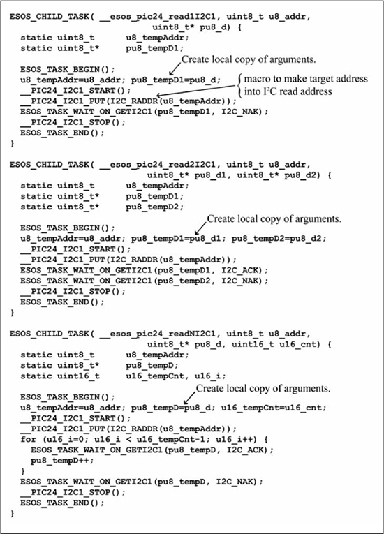
Application Using the ESOS I2C Service and Semaphores
The ESOS I2C service created in the previous section allows you to easily build ESOS applications to use I2C devices. The circuit in Figure 10.51 shows how to connect the dsPIC33EP128GP502 to the Maxim Integrated Circuits DS1631 I2C thermometer and thermostat. Figure 10.54 gives the single application version of the code used to read the current temperature from the DS1631. Although the DS1631 measures the temperature and the PIC24 μC can read this temperature via I2C, you must write data to the I2C bus to configure the DS1631 and to command the DS1631. This application exercises a large portion of the I2C services ESOS created. This section demonstrates an ESOS application to recreate the results obtained by the code in Figure 10.54 using the ESOS services for semaphores and I2C transactions.
Figure 14.32 shows the initialization code of the ESOS application. The routine user_init() performs the normal initialization operations of configuring the heartbeat LED, creating semaphores and registering tasks and timers. The user_init() in Figure 14.32 also calls the ESOS I2C configuration routine esos_pic24_configI2C1 to set the PIC24 μC I2C peripheral to transfer at 400 kbps. Notice that the global variables include three semaphores and a 16-bit integer i16_temp to hold the temperature conversion results.
Figure 14.32
ESOS application for testing the DS1631 using semaphores (part 1)
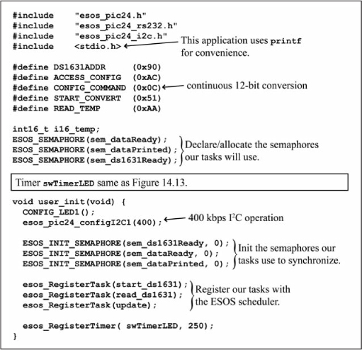
The DS1631 must be configured and commanded via I2C transactions to start temperature conversions. Thus, the DS1631 cannot be started in the routine user_init(), because user_init() is not an ESOS function and cannot wait or yield. Since the DS1631 must receive I2C data to operate properly, initialization and command of the DS1631 must occur in ESOS user tasks. Figure 14.33 shows the user tasks to complete the application. The task start_ds1631 performs two I2C transactions to configure the DS1631 for 12-bit conversion results and to convert the temperature continuously. After the DS1631 is commanded to start conversions, the task start_ds1631 waits for a period of time to allow the DS1631 to acquire the first temperature reading. The task start_ds1631 signals the task read_ds1631 that the DS1631 is operating, and then the task start_ds1631 ends.
Figure 14.33
ESOS application for testing the DS1631 using semaphores (part 2)
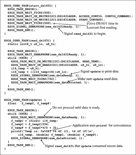
Simultaneously with the execution of start_ds1631, the task read_ds1631 starts. Initially, task read_ds1631 waits on notification from start_ds1631 that the DS1631 is ready to provide temperature data. Once task read_ds1631 gets the signal, it enters an infinite loop where it performs an I2C transaction to acquire the most recent temperature reading from the DS1631. Task read_ds1631 places the results in the global variable i16_temp and signals task update that new temperature data is ready for its use. After signaling update, read_ds1631 waits for 750 ms and checks to see if task update has, indeed, consumed the temperature data. Once task update has signaled, read_ds1631 loops back to repeat the process.
Upon being registered in user_init(), task update starts executing. Initially, task update waits for a signal from task read_ds1631 that temperature data is available. Once the signal is received, task update converts the raw binary DS1631 data into a floating-point temperature and prints the results to the serial output port. After the results are printed, the temperature data are no longer needed and task update signals task read_ds1631 that it can overwrite the results with new data. Task update repeats these functions continuously.
In order to fully mimic the results of the code in Figure 10.54, the user task in Figure 14.33 uses the printf function in stdio.h. Use of printf could theoretically block the task update if the communication channel were not functioning properly. A blocked task update would also block other tasks from executing. A typical ESOS application would use the ESOS communication service function calls introduced in the previous sections to facilitate cooperative multitasking and allow the other unblocked tasks to continue to operate even when communication is slow or not functioning.
Application Using the ESOS I2C Service and Messaging
In the previous section, you saw how semaphores can be used to coordinate or synchronize ESOS tasks as they read the DS1631 temperature sensor and display its value. However, the semaphores only provide the task synchronization. The actual temperature data was conveyed in global variables. Thus, two separate mechanisms are used to accomplish the related tasks: task coordination/synchronization and data communication. Messaging between ESOS task can accomplish both simultaneously. In this section, you create an ESOS application to recreate the results obtained by the code in Figure 10.54 and Figures 14.32 and 14.33 using the ESOS services for messaging and I2C transactions.
Figure 14.34 shows the initialization code of the ESOS application. The routine user_init() performs the normal initialization operations of configuring the heartbeat LED, and registering tasks and timers. The user_init() in Figure 14.34 also calls the ESOS I2C configuration routine esos_pic24_configI2C1 to set the PIC24 μC I2C peripheral to transfer at 400 kbps.
Figure 14.34
ESOS application for testing the DS1631 using messaging (part 1)
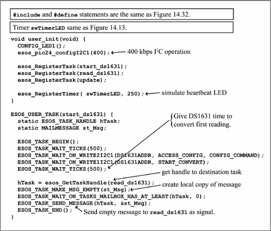
The DS1631 must be configured and commanded via I2C transactions to start temperature conversions. Thus, the DS1631 cannot be started in the routine user_init(), because user_init() is not an ESOS function and cannot wait or yield. Since the DS1631 must receive I2C data to operate properly, initialization and command of the DS1631 must occur in ESOS user tasks. Figure 14.34 shows a user task called start_ds1631, which initializes the DS1631 device. The task start_ds1631 performs two I2C transactions to configure the DS1631 for 12-bit conversion results and to convert the temperature continuously. After the DS1631 is commanded to start conversions, the task start_ds1631 waits for a period of time to allow the DS1631 to acquire the first temperature reading. Then, the task start_ds1631 creates an empty mail message—a message with no data payload—and sends this message to the read_ds1631 task. At this point, the job of the start_ds1631 task is complete, and task start_ds1631 ends.
Figure 14.35
ESOS application for testing the DS1631 using messaging (part 2)
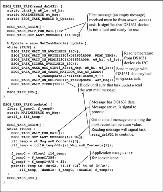
Simultaneously with the execution of task start_ds1631, the task read_ds1631 in Figure 14.35 starts. Initially, task read_ds1631 waits on notification from start_ds1631 that the DS1631 is ready to provide temperature data. This notification comes in the form of the (empty) mail message sent by task start_ds1631 before it ended. Once task read_ds1631 reads this mail message signal, it enters an infinite loop where it performs an I2C transaction to acquire the most recent temperature reading from the DS1631. Task read_ds1631 creates a mail message capable of carrying two 8-bit data values. The two data bytes read from the DS1631 are copied into this mail message, and the message is sent to the update task. Reception of this mail message by the update task means that new temperature data is available, and the mail message contains that data. The combination of signal and data communication should be contrasted with the semaphore and global variables used in Figures 14.33 and 14.34. Task read_ds1631 blocks execution until it is confirmed that the update task has received the message. Once task update has received new temperature data, the read_ds1631 task loops back to repeat the process.
Upon being registered in user_init(), task update starts executing. Initially, task update waits for mail message from task read_ds1631 that contains the DS1631 temperature data. Task update gets the most recent message from its mailbox discarding any older messages that may exist. Thus, task update has the most current temperature data from the DS1631. Also, note that task update’s call to ESOS_TASK_GET_LAST_MESSAGE() will cause task read_ds1631 to continue from its blocked ESOS_TASK_WAIT_ON_DELIVERY() statement. Once the message is received, task update converts the raw binary DS1631 data into a floating-point temperature and prints the results to the serial output port. Task update repeats these functions continuously.
In order to fully mimic the results of the code in Figure 10.54, the user tasks in Figures 14.33 and 14.35 uses the printf function in stdio.h. Use of printf could theoretically block the task update if the communication channel were not functioning properly. A blocked task update would also block other tasks from executing. A typical ESOS application would use the ESOS communication service function calls introduced in the previous sections to facilitate cooperative multitasking and allow the other unblocked tasks to continue to operate even when communication is slow or not functioning.
Summary
This chapter introduced concepts of multitasking OSes and provided an introduction to ESOS, a lightweight cooperative multitasking OS for the PIC24 μC. ESOS provides services for managing user tasks including subordinate child tasks, full-featured wait/yield conditions, mailboxes, and semaphores. ESOS also provides a collection of services so that the user can exploit the powerful hardware peripherals of the PIC24 μC. Services provided by ESOS include software timers, asynchronous and synchronous communications, and hardware interrupts.
Review Problems
1. Develop the code required to implement a rendezvous semaphore with four tasks instead of two.
2. Implement a binary semaphore with function similar to Figure 14.19 using the ESOS-provided user flags. A binary semaphore can take on only the values 0 and 1.
3. C language macros are used extensively in ESOS. The multiline code macros are surrounded by do-while (0) statements. Why is this construction necessary?
4. Using basic ESOS I2C operations, create a specialized service for the Maxim Integrated Circuits DS1631 Digital Thermometer and Thermostat. The service will be composed of child tasks that perform the DS1631 operations directly without using the I2C transaction functions. Create the supporting macros to make the service’s use in user tasks simpler. Some example macro names include ESOS_TASK_WAIT_GET_TEMP and ESOS_TASK_WAIT_SET_THERMOSTAT.
5. Reconstruct the system in Figures 9.25 and 9.26 using ESOS.
6. Reconstruct the system in Figures 10.56 through 10.61 using ESOS.
7. Reconstruct the system in Figures 11.21 through 11.24 using ESOS.
8. Reconstruct the system in Figures 12.27 and 12.28 using ESOS.