
The basic concepts of 3D graphics will be used in the native part of your game. As you can see, these concepts can be sometimes complex and difficult, as well as involve a lot of mathematical calculations, especially related to matrices. Therefore, creating the whole implementation of a 3D game from scratch will not be a trivial task. Fortunately, Direct3D may significantly simplify creation of 3D games and applications. Furthermore, the Windows Phone XAML and Direct3D App template automatically generates code that is related to the Direct3D setup. It also creates a simple example with a rotating cube. This section explains the role of some files from the native part.
The native part of the project is named SpaceAim3DComp and is created as the Windows Phone Runtime Component. As mentioned in the previous chapters, this part prepares 3D graphics (using Direct3D) to display in the application page from the managed part. As stated at http://msdn.microsoft.com/library/jj207012, this:
"creates a Direct3D graphics device, which it uses to create a Texture that is shared with the XAML app"
The process of drawing graphics and showing them in the DrawingSurface control is presented in the following diagram:
To start, Direct3D is used to draw elements directly to the texture, which is synchronized to prevent concurrent access to it by both the Direct3D and XAML parts. By using synchronization, only one of the parts can operate at a time. The last stage of the drawing process consists of graphics presentation in the DrawingSurface control, which is handled by the XAML engine.
The first class explained in this chapter is Direct3DInterop, whose code can be found in the Direct3DInterop.h and Direct3DInterop.cpp files. It is used to communicate between the native and the managed part of the application, as shown in the following figure:
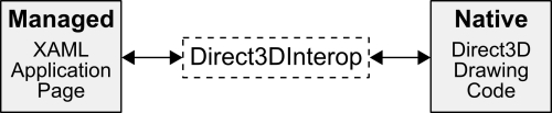
The class is declared with the ref class keyword, thus it is a C++/CX class. It implements the IDrawingSurfaceManipulationHandler interface (from the Windows::Phone::Input::Interop namespace) and defines the SetManipulationHost method, which is used to prepare event handlers for touch input. It is important to understand the order in which particular event handlers are called. Whenever the user clicks on the screen, OnPointerPressed is called once. If the user stops clicking on the screen, OnPointerReleased is called. While clicking, the player can move a finger and then the OnPointerMoved method is called.
The Direct3DInterop class also has a set of properties that allow to obtain data related to window bounds (WindowBounds) and resolutions (NativeResolution and RenderResolution). Apart from them, it contains a few private fields that represent, for example, a renderer that prepares graphics using Direct3D (m_renderer) and a timer (m_timer). The class has also two events, RequestAdditionalFrame and RecreateSynchronizedTexture. The first one indicates the necessity of rendering the content as soon as possible, and the other, the necessity of recreating the synchronized texture.
One of the methods is Connect, which is used to create a suitable renderer (CubeRenderer instance), initialize it (by calling the Initialize method), and pass values indicating window size and resolution. The Connect method is called after a successful creation of the Direct3D device and the texture. The Disconnect method can be understood as the opposite to Connect. In this example, it is used just to assign a null pointer (nullptr) to the m_renderer field, which indicates that the renderer is no longer used.
The PrepareResources method is called for each frame and can indicate whether the content needs to be rendered. It can be done by setting a suitable value of the contentDirty variable, whose pointer is passed as a parameter.
Two other methods are named GetTexture. One of them has three parameters, and the other does not require any of them. They also vary by a return type. The first one calls the Update and Render methods from the renderer class, fires the RequestAdditionalFrame event, and causes redrawing of the content. The second version of this method just returns a pointer to the synchronized texture.
The Direct3DBase is a base class for the renderer and contains a set of virtual methods, including the CreateDeviceResources method. It creates the Direct3D device (the m_d3dDevice field) and the corresponding context (m_d3dContext).
Note
While programming using Direct3D, you may often use either the Direct3D device or the Direct3D device context. The first is represented by the ID3D11Device interface and performs crucial role for creating necessary resources. Regarding the other, it is specified by ID3D11DeviceContext and is used for rendering.
Another method is named CreateWindowSizeDependentResources and creates the resources that are dependent on a window size, including the texture as the render target buffer. It is prepared by the CreateTexture2D method and stored in the m_renderTarget field, which is a pointer to the D3D11Texture2D instance. The class also prepares the depth stencil view.
Among the other methods in the Direct3DBase class, the Initialize method is available. This method calls CreateDeviceResources and prepares resources required by Direct3D.
The CubeRenderer.h and CubeRenderer.cpp files are related to the CubeRenderer class. This class derives from Direct3DBase and is used for rendering a rotating cube. You will significantly modify this file to present the game world with the planet and asteroids.
The CubeRenderer class has a set of fields. The first one, named m_loadingComplete, indicates whether the process of loading required resources is finished. A value is used to prevent drawing the cube until all resources have been loaded successfully.
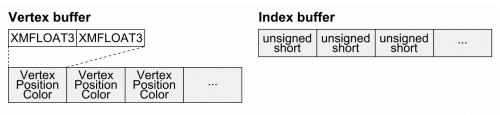
Two other fields represent the vertex and index buffers (m_vertexBuffer and m_indexBuffer, respectively). Both are pointers to instances of the ID3D11Buffer structure. Their role is to store values that are later used during rendering. Data of each vertex are stored as an instance of the VertexPositionColor structure, while a single index is represented by an unsigned short number, as presented in the following figure:
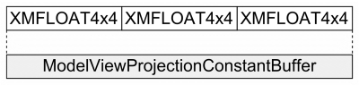
The CubeRenderer class also contains the m_constantBuffer and m_constantBufferData fields. Both are related to the constant buffer, which is the third buffer resource type, along with the vertex and index ones. In the automatically generated template, the constant buffer supplies necessary data (model, view, and projection matrices) for the vertex shader. The m_constantBuffer field is a pointer to ID3D11Buffer, however m_constantBufferData is an instance of the ModelViewProjectionConstantBuffer structure that stores data for the constant buffer, as shown in the following figure:
To render objects (such as the rotating cube), some resources should be loaded. The automatically generated CubeRenderer class has the CreateDeviceResources method. At the beginning, it loads the vertex shader and pixels shader asynchronously from the .cso files (compiled shader object). To prepare the vertex shader, the CreateVertexShader method is called. The result is stored in the m_vertexShader field, which is a pointer to an instance of the ID3D11VertexShader structure. Then, the CreateInputLayout method is called to specify the input data that are passed to the vertex shader program. The result is available by the m_inputLayout field that is a pointer to ID3D11InputLayout. In case of the pixel shader, its data are accessible by the m_pixelShader field, which is a a pointer to an instance of the ID3D11PixelShader structure. Then, the constant buffer is created using the CreateBuffer method.
When the vertex and pixel shaders are prepared, the application creates both the vertex and index buffers. To create the first one, vertex positions and colors are specified in an array and the CreateBuffer method is called with suitable parameters, shown as follows:
CD3D11_BUFFER_DESC vertexBufferDesc(sizeof(cubeVertices),
  D3D11_BIND_VERTEX_BUFFER);
DX::ThrowIfFailed(m_d3dDevice->CreateBuffer(&vertexBufferDesc,
  &vertexBufferData, &m_vertexBuffer));
It is worth mentioning that the type of buffer is chosen according to the value passed in the constructor of CD3D11_BUFFER_DESC. In case of the vertex buffer, the D3D11_BIND_VERTEX_BUFFER enumeration value is used. However, to prepare the index buffer you should use D3D11_BIND_INDEX_BUFFER instead. Apart from the index buffer, a value of m_indexCount is set to a number of indices.
When the cube vertices and indices are prepared correctly, the m_loadingComplete variable is set to TRUE. This means that the mechanism has already loaded all required resources and the content can be rendered.
Some resources are dependent on the window size and need to be recreated whenever the window size is changed. The CreateWindowSizeDependentResources method is called in such a case. Here, the aspect ratio is calculated by dividing the window width by its height. Another required value is the
field of view (FOV). It indicates what angle is used to see the game world. In case of smaller values, a smaller area of the scene is visible. You can adjust the value of this parameter according to the game scenario.
When the aspect ratio and the field of view are available, the projection matrix is calculated, as shown in the following code:
XMStoreFloat4x4(&m_constantBufferData.projection,
  XMMatrixTranspose(XMMatrixPerspectiveFovRH(fovAngleY,
    aspectRatio, 0.01f, 100.0f)));
The XMMatrixPerspectiveFovRH method takes four parameters, namely field of view, aspect ratio, near z distance, and far z distance. The last two prevent from drawing objects that are too close (the NearZ parameter) or too far (FarZ) from the camera. By using the XMStoreFloat4x4 function, you store the calculated matrix into the projection field of the constant buffer data. The matrix is transposed by calling the XMMatrixTranspose method.
The game should perform some operations while running and adjust the objects according to the current state. For instance, the rocket should be moved and the game should check whether a collision with any asteroid or the planet occurs. To achieve this, you can use the Update method that is called for each frame. This is a suitable place for the logic that updates the view or model matrices according to the movement of the object or the camera.
In case of the rounding cube example, the view matrix is not changeable and is calculated by the following code:
XMStoreFloat4x4(&m_constantBufferData.view,
  XMMatrixTranspose(XMMatrixLookAtRH(eye, at, up)));
The XMMatrixLookAtRH function takes three parameters, which represent the location of the camera (EyePosition), the location in the scene on which the camera should be focused (FocusPosition), and a vector indicating an upward direction (towards Y positive values, UpDirection parameter). After transposition, the matrix is stored in the view field of the constant buffer data.
You can also create the view matrix by providing the camera position, a vector indicating an upward direction, and a vector indicating the camera direction (instead of a location on which the camera should be focused). It can be achieved by the XMMatrixLookToRH or XMMatrixLookToLH methods, depending on the coordinate system.
The second operation performed in the Update method, is rotating the cube, which is performed by the following code snippet:
XMStoreFloat4x4(&m_constantBufferData.model,
  XMMatrixTranspose(XMMatrixRotationY(timeTotal * XM_PIDIV4)));
The XMMatrixRotationY function takes only one parameter and returns a calculated matrix. In the example, a rotation is made according to the value indicating the total time of the game (timeTotal) multiplied by π/4 (XM_PIDIV4). The calculated rotation matrix is transposed and stored in the model field of the constant buffer data, as presented earlier.
A rotation can be performed by calling the XMMatrixRotationX, XMMatrixRotationY, and XMMatrixRotationZ functions (around x, y, and z-axis respectively by a given angle), XMMatrixRotationAxis (around a specified axis by a given angle), and XMMatrixRotationRollPitchYaw (around x, y, and z-axis by given angles).
Apart from the rotation, each mesh (a set of data such as vertices, representing an object) can be translated. It is performed by the XMMatrixTranslation or XMMatrixTranslationFromVector methods. Both allow to calculate a matrix, which moves the object in any direction.
Scaling is another transformation that involves calculating a matrix. You can use the XMMatrixScaling and XMMatrixScalingFromVector methods to perform this operation. Both make it possible to scale the same object differently along various axes.
After execution of the CreateWindowSizeDependentResources and Update methods, proper values are inside the constant buffer data, however, nothing has been rendered yet. The CubeRenderer class contains the Render method that has code that makes it possible to render the simple rotating cube on the screen.
At the beginning, the render target view (using the texture) and depth stencil view are cleared. The second parameter of the ClearRenderTargetView method specifies the color that is used to fill the background. Later, the value of the m_loadingComplete variable is verified. If it is equal to FALSE, execution of the Render method is finished. Otherwise, the render target view is bound by calling the OMSetRenderTargets method. The next step consists of copying data prepared for the constant buffer (storing model, view, and projection matrices) to the constant buffer represented by the ID3D11Buffer.
The IASetVertexBuffers and IASetIndexBuffer methods prepare the vertex and index buffers before drawing. They are related to the input-assembly stage that is executed before the shaders are run.
The IASetPrimitiveTopology method specifies how indices and vertices data should be interpreted while drawing objects. One of the common possibilities is using them as a list of triangles (D3D11_PRIMITIVE_TOPOLOGY_TRIANGLELIST enumeration value).Thus, vertices related to each of the three indices are taken to form a single triangle. The next three are used to create the second triangle. Other possibilities include an interpretation of data as points list or lines list (D3D11_PRIMITIVE_TOPOLOGY_POINTLIST and D3D11_PRIMITIVE_TOPOLOGY_LINELIST, respectively). By changing this setting, you can adjust the way how objects are rendered.
The IASetInputLayout method is also related to the input-assembler stage. It binds an object with information about an input for the vertex shader, that is, a layout of the vertex buffer.
The names of the next two methods called in Render, start with the VS prefix. This prefix indicates that they are related to the vertex shader and allow you to set it (VSSetShader), as well as set the constant buffer (VSSetConstantBuffer). The next method is named PSSetShader and simply sets the pixel shader.
At the end of the Render method, DrawIndexed is called. This indicates which indices from the index buffer should be used. Here, all indices are chosen.
As you can see, two shaders (the vertex and pixel ones) have already been loaded in the CreateDeviceResources method. The code of the first one is available in the SimpleVertexShader.hlsl file. Here, you can find information about a constant buffer, as well as input and output of the vertex shader. In this case, both input and output store the position and color of the vertex. To calculate the position, a few matrix multiplications are performed, the model matrix is multiplied by the view matrix, and the result is multiplied by the projection matrix. The color is copied without any changes.
The pixel shader is created in the SimplePixelShader.hlsl file. An input of the pixel shader is specified as a structure (PixelShaderInput) with information about a position and color. The shader returns the color exactly the same as passed in the input data.
You learned some basic information about rendering the content using Direct3D in Windows Phone 8 applications. Therefore, it can be beneficial to return for a moment to the code of the GamePage.xaml.cs file from the managed part. Now, it should be much easier to understand its content.
The most interesting part, from the perspective of the native game development, is the DrawingSurface_Loaded method. Here, a new instance of the Direct3DInterop class is created. Next steps consist of setting suitable window bounds (according to the width and height of the DrawingSurface control), as well as the native and render resolutions. Later, a content provider is set (using the SetContentProvider method), and an instance of the Direct3DInterop class receives access to manipulation events from the DrawingSurface control (by calling the SetManipulationHandler method).