
In the previous chapters, you worked on the managed part of the project, which is composed of a set of screens that allow the user to navigate through the game, see ranks, or view a map with players in the vicinity. In this chapter, a short introduction to the 3D graphics is presented. You will learn how the game world is composed, how models can be represented, as well as what role is performed by model, view, and projection matrices. You will also get to know the automatically generated template for the Direct3D-based part of the project.
The native game development is presented using C++, C++/CX, and Direct3D, that allow you to achieve high performance, which may be crucial in case of complex 3D games. Let's learn some subjects that you will use in the next chapter for preparing the first prototype of the Space Aim 3D game!
3D graphics is a complex subject, however, it is important to understand its basic concepts before starting development. 3D graphics allow to create a game world that contains many models. Each of these can be placed at a specified location in the scene. The objects can be transformed, which makes it possible to translate, rotate, or scale them. In case of the example game, the world is a limited part of the space, where exactly one planet and many asteroids are located. Each of them is placed in a different location and rotates with random speed.
Another interesting question is, which part of the game world should be presented? Do you need to see all asteroids with the target planet in the background, or maybe you want to see the planet in the foreground? You can answer these questions by specifying the location of the camera. In case of Space Aim 3D, the camera is placed on the rocket and is facing towards the planet, so the view will be changed while the rocket is flying.
Games, even for mobile platforms, can present realistic graphics. This can be achieved with additional features such as lighting, materials, and textures. The last two allow to specify the characteristics of the object surface, as well as render it using a special image, which can be very similar to the object in the real world. In many scenarios, elements placed in scene are even equipped with a set of animations.
There are a lot of topics regarding 3D graphics, but in this book only basic concepts are presented and explained. However, these few topics can provide a good grounding for further adventure with 3D game development.
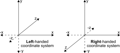
As mentioned earlier, the game world contains a set of objects, placed in particular locations. However, you need a way of describing the single object. This can be specified by a set of vertices. Each vertex has a location indicated by the x, y, and z coordinates, given in a particular coordinate system. Here are two main coordinate systems: left-handed and right-handed. The difference between the left-handed and right-handed coordinate system is quite simple. In the first one, values of z coordinate increase into the screen, while in the other, they increase towards you, as shown in the following figure:
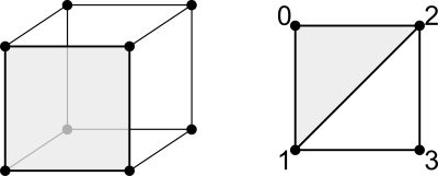
A set of vertices (represented by black dots in the following figure) is not enough for rendering the model because the mechanism does not know how to connect them. To solve this problem, you can group vertices into groups of three to create triangles, which form faces. As shown in the following figure, the front part is composed of two triangles, presented in grey (1, 0, 2 vertices) and white (1, 2, 3 vertices). To provide information required for rendering the object, additional data is used, which stores an order in which particular vertices should be taken and drawn as triangles.
In Direct3D, data of vertices and indices are stored as vertex and index buffers respectively. The vertex buffer stores data of all the vertices, and can include their positions and colors. In case of the example cube model, the vertex buffer stores data of eight vertices.
The index buffer is used to store indices in a suitable order. As an example, the front part of the cube requires the following content in the buffer: 1, 0, 2, and 1, 2, and 3. The first three values represent the first face, while the second three values represent the second face. Of course, you can add other faces in a similar way.
To correctly render the game world on the screen, it is necessary to prepare model, view, and projection matrices for particular objects.
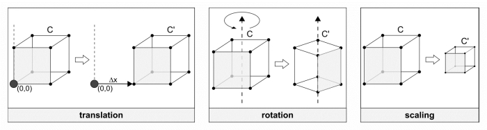
The model matrix describes the object in the game world and allows to perform various transformations such as translation (moving the object in a specified direction for a given distance), rotation (along the x, y, or z axis), and scaling (in a particular axis). This matrix can be understood as a way of telling how each single object is located in the scene. In case of your game, you need to create separate model matrices for each asteroid and planet, because all of them rotate at random speeds.
The translation, rotation, and scaling transformations are as follows:
The view matrix represents the location and direction of the camera. Thus, it determines which part of the scene you can see and how far are various objects. It is worth mentioning that this matrix should be updated every time the position of the camera changes. In case of Space Aim 3D game, the view matrix is updated while the rocket is flying towards the target planet, and the same can be used by all the objects.
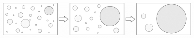
The projection matrix specifies how a 3D world is presented on a 2D screen. It can use a perspective to calculate the size of an object based on its distance from the camera. This is a common approach that can also be observed in the real world. However, for some specific reasons, it could be beneficial to present the model in the same size, regardless of its distance from the camera. This can be achieved in the orthographic mode. In your game you will use the approach that shows a perspective. Thus, the sizes of the asteroids and the planet will change, depending on their distance from the rocket. If it is far, objects are smaller. While coming closer, asteroids and the planet become bigger, as shown in the following figure:
You have learned the basics of how the models are represented in memory, and have explained the vertex and index buffers, as well as the model, view, and projection matrices. Now, let's take a look at the operations performed to convert a 3D scene into a 2D raster, which is an image consisting of a grid of pixels. The process consists of a few stages and is called the rendering pipeline. A simple version (skipping some additional stages) is presented as follows:
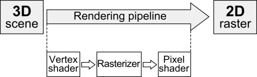
For each vertex of a model from the 3D scene, the vertex shader is executed. Then, the rasterizer performs its role. Finally, for each pixel, the pixel shader is executed.
The vertex shader and pixel shader are programs written in specialized languages such as HLSL (High Level Shader Language). HLSL is very similar to the C language, but is equipped with some additional features. Shaders are used to set the properties of vertices and pixels according to the given algorithm. They are executed on the GPU (Graphics Processing Unit) and perform operations concurrently. It is worth mentioning that shaders are run very often, thus, their code should be prepared in the most efficient way.
The vertex shader performs operations on a single vertex and returns data about a single vertex. Its aim is to transform the position of the vertex from a 3D scene into a 2D location on the screen. It can specify not only the location of the vertex, but also texture coordinates or colors.
The pixel shader performs a different role than the vertex shader does, because it calculates the color of a particular pixel and optionally additional pixel properties. It can be used, for example, for lighting per pixel scenarios.