
45
3
SimulationofNight‐Visionand
InfraredSensors
Frank Kane
Sundog Software, LLC
Many action games simulate infrared (IR) and night-vision goggles (NVG) by
simply making the scene monochromatic, swapping out a few textures, and turn-
ing up the light sources. We can do better. Rigorous simulations of IR and NVG
sensors have been developed for military training and simulation applications,
and we can apply their lessons to game engines. The main differences between
visible, IR, and near-IR wavelengths are easily modeled. Sensors may also in-
clude effects such as light blooms, reduced contrast, blurring, atmospheric trans-
mittance, and reduced resolution that we can also simulate, adding to the realism.
3.1ThePhysicsoftheInfrared
The world of the infrared is a very different place from the world of visible
light—you’re not just seeing reflected sunlight, you’re seeing how objects radiate
heat. Accurately representing an IR scene requires understanding some basic
thermodynamics.
Fortunately, the bit we need isn’t very complicated—we can get by with just
an understanding of the Stefan-Boltzmann law. It tells us that the black body ra-
diation
*
j
of an object is given by
*4
j εσT
.
Here, T is the absolute temperature of the object (in Kelvins),
is the thermal
emissivity of the material, and
is the Stefan-Boltzmann constant,
8
5.6704 10
124
Js m K
. If the ambient temperature and temperature of the objects in your
46
scene re
m
special
I
simulati
o
ulate ob
j
and/or t
e
perature
Tab
l
that mo
s
b
lack b
o
It is
your sc
e
may be
s
their ow
n
tempera
t
modelin
g
of emis
s
tures is
r
To
a
in the vi
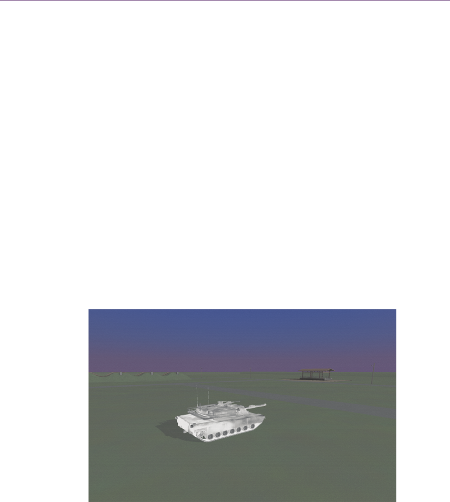
Figure
3
courtesy
o
m
ain consta
n
I
R versions
o
o
n of a tank
(
j
ects coolin
g
e
xtures and c
va
r
ies.
l
e 3.1 lists e
m
s
t organic m
a
o
dies, while
m
the subtle di
f
e
ne that are
a
s
mall, they a
r
n
(i.e., the in
t
t
ure are the
m
g
your mater
i
s
ivity and ab
s
r
equired.
a
dd additiona
l
s
ible light te
x
.1. Simulated
o
f SDS Intern
a
n
t,
t
he radiati
o
o
f your textu
r
(
note the trea
d
g
off over ti
m
ompute the
e
m
issivity val
u
a
terials have
m
etals are mo
r
f
ferences in
e
a
t the same
a
r
e important
t
erior of a he
a
m
ain source o
f
i
als and text
u
s
olute tempe
r
l
detail to th
e
x
ture as well
—
image of ph
y
a
tional.)
3.Simulat
o
n emitted m
a
r
e maps. Fig
u
d
s and engin
e
m
e, just stor
e
e
quation abo
v
u
es for some
high emissi
v
r
e reflective
a
e
missivity th
a
a
mbient tem
p
for adding d
e
a
ted house o
r
f
contrast in
y
u
res in terms
o
r
ature. An alt
e
e
IR scene, t
h
—
in a pinch,
t
y
sically
b
ased
ionofNight‐
V
a
y be preco
m
u
re 3.1 illustr
e
area are hot
e
the emissiv
v
e in a verte
x
common m
a
v
ity and beh
a
a
nd have low
e
a
t distinguish
p
erature; alt
h
e
tail. For obj
r
living orga
n
y
our IR scen
e
o
f RGB colo
r
ernate set of
h
ere is a phys
t
his lets you
r
IR fused wit
h
V
isionandIn
f
m
puted and b
a
r
ates texture-
b
t
). If you wa
n
v
ity in your
m
x
program as
a
terials at 8
µ
a
ve almost l
i
e
r IR emissio
different ma
t
h
ough the di
f
ects that emi
n
isms), the c
h
e
. Stop thinki
n
r
s, but rather
materials an
d
ical basis to
b
r
epurpose th
e
h
visible ligh
t
s
f
raredSenso
r
a
ked into
b
ased IR
n
t to sim-
m
aterials
the tem-
µ
m. Note
i
ke ideal
ns.
t
erials in
f
ferences
t heat of
h
anges in
n
g about
in terms
d
/or tex-
b
lending
e
visible-
s
. (Image
r
s

3.1ThePhysicsoftheInfrared 47
Material Emissivity Material Emissivity
Aluminum 0.20 Paint 0.84 (white)–0.99 (black)
Asphalt 0.95 Paper 0.95
Cast iron 0.70–0.90 Plastic 0.95
Clay 0.95 Rusted iron 0.60–0.90
Cloth 0.95 Sand 0.90
Glass 0.85 Snow 0.90
Granite 0.90 Soil 0.90–0.98
Grass 0.98 Steel 0.80–0.90 (cold-rolled), 0.25 (polished)
Gravel 0.95 Tin 0.10–0.30
Human skin 0.95 Water 0.93
Ice 0.98 Wood 0.90–0.95
Table 3.1. Emissivity of common materials.
light textures of your objects as detail for the thermal information. There is a
range of about 0.15 in the emissivity between white and black objects; light col-
ors reflect more heat, and dark colors absorb it. Your fragment shader may con-
vert the RGB values of the visible-light textures to monochromatic luminance
values and perturb the final emissivity of the fragment accordingly. Listing 3.1
illustrates a snippet of a fragment shader that might approximate the thermal ra-
diation of a fragment given its visible color and knowledge of its underlying ma-
terial’s emissivity and temperature. This is a valid approach only for objects that
do not emit their own heat; for these objects, emissivities and temperatures
should be encoded directly in specialized IR textures, rather than blending the
visible-light texture with vertex-based thermal properties.
uniform sampler2D visibleTexture;
uniform sampler2D thermalTexture;
uniform float level;
uniform float gain;
uniform float stefanBoltzmannConstant;
uniform float emissivityBlendFactor;

48 3.SimulationofNight‐VisionandInfraredSensors
varying float materialEmissivity;
varying float materialTemperature;
void main()
{
vec3 texCoords = gl_TexCoord[0].xy;
vec3 visibleColor = texture2D(visibleTexture, texCoords).xyz;
// Convert color to luminance.
float visibleLuminance = dot(vec3(0.2126, 0.7152, 0.0722),
visibleColor);
// Convert luminance to thermal emissivity.
float emissivityFromColor = (1.0 – visibleLuminance) * 0.15 + 0.84;
// Blend the material-based emissivity with the color-based.
float finalEmissivity = mix(materialEmissivity,
emissivityFromColor, emissivityBlendFactor);
// Stefan–Boltzmann equation:
float radiation = finalEmissivity * stefanBoltzmannConstant *
materialTemperature * materialTemperature *
materialTemperature * materialTemperature;
// Apply auto-gain control.
float mappedRadiation = (radiation * gain) + level;
// In a "white-hot system," we're done:
gl_FragColor = vec4(mappedRadiation, mappedRadiation,
mappedRadiation, 1.0);
}
Listing 3.1. A simplified fragment shader for IR sensor simulation using a hybrid of visible-light
textures with material-based thermal properties.
Atmospheric transmittance should also be applied to IR scenes, just as we
apply fog to simulate visibility effects in visible light. In the IR band, however,
visibility is largely ruled by the humidity in the air and not by the particles in it.
Water in the air absorbs heat quite effectively, although IR still provides superior
visibility in foggy conditions. Military-grade simulations apply rigorous atmos-

3.2SimulatingInfraredSensorEffects 49
pheric transmittance models for this purpose such as LOWTRAN
1
and MOD-
TRAN,
2
but we can get by with a simpler approximation. Atmospheric transmit-
tance from water vapor for a wavelength
in micrometers is approximated
[Bonjean et al. 2006] by
20mω
λωλ
ττ
.
Here,
is the depth of precipitable water in millimeters; this is a measure of the
air’s humidity. Typical values range from 10 to 60 mm. The value
ωλ
τ
is given
by:
2
0.0075
10
λ
ωλ
τ
.
The value of m represents the air mass, which is a measure of how much atmos-
phere the heat source has passed through before reaching the sensor. This is a
unitless value, normalized to one for a vertical path through the atmosphere at sea
level. More sophisticated implementations for “serious games” may also take
atmospheric scattering and scattering from dust into account.
3.2SimulatingInfraredSensorEffects
The Stefan-Boltzmann law gives you the simulated radiation being emitted from
an object in your scene, but that’s not directly useful for rendering. You need to
map these radiation values into monochromatic luminance values that are dis-
playable—real sensors have a feature called auto gain control that does this.
Typically, they compute the range of radiation values in the visible scene and
map these values linearly from 0.0 to 1.0. The range being mapped can be quite
high—the night sky’s temperature is near absolute zero, while a missile’s exhaust
could be several thousand Kelvins [Thomas 2003].
The actual colors used to represent this radiation vary by the type of sensor.
Most forward-looking infrared (FLIR) sensors used by the military represent IR
in black and white, and are configurable between “black-hot” and “white-hot”
polarities (shown in Figure 3.2). Thermal imaging sensors may blend between
red for hot spots in the image and blue for cold spots. These are all easy effects to
achieve in a fragment program.
In addition to modeling gain and polarity, there are many imperfections in IR
sensors that we can also emulate. Older CRT-based devices were prone to effects
1
See http://www1.ncdc.noaa.gov/pub/software/lowtran/.
2
See http://www.modtran.org/.
..................Content has been hidden....................
You can't read the all page of ebook, please click here login for view all page.